DEVELOPMENT OF GRAPHICAL USER INTERFACE (GUI) OF CAN BUS
DASHBOARD
Nur Sakinah Binti Mohd Ismail Bachelor of Electrical Engineering (Control, Instrumentation & Automation)
" I hereby declare that I have read through this report entitle "Development Of A Graphical User Interface (GUI) Of Controller Area Network (CAN) Bus Dashboard" and found that it has comply the partial fulfilment for awarding the degree of Bachelor of Electrical Engineering (Control, Instrumentation and Automation)"
Signature :
Supervisor’s Name : Ahmad Fairuz Bin Muhammad Amin
DEVELOPMENT OF A GRAPHICAL USER INTERFACE (GUI) OF CAR DASHBOARD FROM CONTROLLER AREA NETWORK (CAN) BUS
NUR SAKINAH BINTI MOHD ISMAIL
A Report submitted in partial fulfilment of the requirements for the degree of Electrical Engineering (Control, Instrumentation and Automation)
Faculty of Electrical Engineering
UNIVERSITI TEKNIKAL MALAYSIA MELAKA
I declare that this report entitle "Development Of A Graphical User Interface (GUI) Of Controller Area Network (CAN) Bus Dashboard" is the result of my own research except as cited in the references. The report has not been accepted for any degree and is not concurrently submitted in candidature of any other degree.
Signature :
Name : Nur Sakinah Binti Mohd Ismail
ii
ACKNOWLEDGEMENT
In the name of Allah, the Most Gracious and the Most Merciful. Alhamdulillah, all praises to Allah for the strengths and His blessing for me completing this Final Year Project II report.
I would like to take this golden opportunity to express my deepest appreciation to my final year project supervisor, Mr. Ahmad Fairuz Bin Muhammad Amin for being a dedicated lecturer guiding me through this project to run smoothly. This project cannot be completed and perfected if without the valuable suggestion and useful information from my supervisor. His patience and enthusiastic in guided me through this final year project have gave me a great courage in completing this project.
Furthermore, I would like to thank my panels Mr.Mohd Safirin Bin Karis and Dr. Lim Kim Chuan for their guidance and provide new idea so that this project can be done perfectly. I would like to express my deepest love and gratitude to my beloved parents, Mr. Mohd Ismail Bin Hj. Roslan and Mrs. Salha Binti Sabar giving me unlimited encouragement especially in moral and investment.
ABSTRACT
Nowadays, most of display system had been using digital and even Graphical User Interface (GUI) to provide the best application system. Purpose of this project is to develop a GUI display for Controller Area Network (CAN) dashboard. In this project, Controller Area Network (CAN) dashboard is chosen to improve their display system application. The CAN was used to control the performance of dashboard. Meanwhile, GUI was designed to display the performance of parameter. Therefore, CAN Bus is specialized to connect interaction between the dashboard and the input of circuit.
CAN is a serial network that was originally designed for the automotive industry. It was primarily used in embedded system and consists of two wires, half duplex, high speed network system. The CAN systems are well suited for high speed application using short wire. GUI is type of user interface allow interaction with electronic devices through graphical icons and visual indicator. This application is designed to make the program interactive and user friendly. By using GUI, user can be free from learning complex command languages.
iv
ABSTRAK
Pada masa kini, kebanyakan system paparan telahmenggunakansistem digital dan juga grafik (GUI) untuk menyediakan system aplikasi yang terbaik. Tujuan projek ini adalah untuk membangunkan satupaparan GUI bagi Kawasan Pengawal Rangkaian (CAN) papanpemuka . Dalamprojekini , Kawasan Pengawal Rangkaian (CAN) papan pemuka makhluk memilih untuk memperbaiki aplikasi system paparanmereka. CAN ini digunakan untuk mengawal prestasi papan pemuka . Sementara itu, GUI telah direka untuk memaparkan prestasi parameter. Oleh itu, CAN Bus adalah khusus untuk menyambung interaksi antara papan pemuka dan input litar.
CAN adalah rangkaian siri yang pada asalnya direka untuk industriautomotif. Iadi gunakan terutamanya dalam system terbenam dan terdiri daripada dua wayar , separuh dupleks , system rangkaian kelajuan tinggi. Sistem CAN baik sesuai untuk aplikasi berkelajuan tinggi menggunakan wayar pendek. GUI adalah jenis antara muka pengguna membolehkan interaksi dengan peranti elektronik melalui ikon grafik dan penunjuk visual . Permohonan ini direka untuk membuat program interaktif dan mesra pengguna. Dengan menggunakan GUI, pengguna boleh bebas daripada mempelajari bahasa arahan kompleks.
TABLE OF CONTENTS
CHAPTER TITTLE PAGE
ACKNOWLEDGEMENT ii
ABSTRACT iii
TABLE OF CONTENT v
LIST OF TABLES vii
LIST OF FIGURES ix
LIST OF ABBREVIATIONS xi
LIST OF APPENDICS xii
1 INTRODUCTION 1
2 LITERATURE REVIEW 4
2.1Type Of Bus 4
2.2Controlled Area Network (CAN) 5
2.3Graphical User Interface (GUI) 7
2.4Related Research Work 2.4.1 Home Appliances
Management System uses Controller Area Network
8
2.4.2 A Design for Automotive CAN Bus Monitoring
8
2.4 3 Graphical User Interface Testing Optimization For
Water Monitoring Application
9
2.4.4 Design Of Electrical Air- Condition Control System For Fuel Cell Vehicle BasedOn CAN Bus
vi
2.4.5 Research On Fault Diagnosis And Forecast System ForestHarvester
Based On CAN- Bus Information
9
2.4.6 Graphical User Interface (GUI) For Thumbprint Image Enhancement and Minutiae Extraction
10
2.4.7 Graphical User Interface for Enhanced Retinal Image Analysis forDiagnosingDiabetic
Retinopathy
10
2.4.8 Graphical User Interface Foe Next Generation Power System
10
2.4.9Speed Trap Detection with Doppler Effect
11
2.4.10 GUI for PC Auto-Shutdown 11
2.4.11 An Introduction to Data Capturing
11
2.4.12 Application Design of Data Packet Capturing Based on
Sharpcap
12
2.4.13 Study on Log-Based Change Data Capture and Handling Mechanism in Real- Time Data Warehouse
12
2.4.14Efficient Data Capturing for Network Forensics in Cognitive Radio Networks
12
2.4.15 The Design of Communication Converter Based on CAN Bus
2.5 Summary 13
3 METHODOLOGY 14
3.1 Introduction 14
3.2 Software Design 18
3.3 Hardware Design 22
3.4 Summary 26
4 RESULT AND DISCUSSION 27
4.1 Software Result 27
4.2 Hardware Result 31
5 CONCLUSION AND
RECOMMENDATION
35
5.1 Conclusion 35
5.2 Recommendation 36
REFERENCES 37
viii
LIST OF TABLES
TABLE TITLE PAGE
3.0 Components used during Hardware
simulation
24
4.0 Result for this project 32
LIST OF FIGURES
FIGURE TITLE PAGE
2.1 Bus network topology 2
2.2 Network with CAN and without
CAN
6
2.3 CAN arbitration 7
3.0 CAN Bus network system 14
3.1 Flow Chart for System Operation 15-17
3.2 Proteus circuit had been design for
simulate coding software
17
3.3 Flow chart for Software Design 19
3.4 COM1 and COM2 was defined 20
3.5 Coding to defined input analogue
data
20
3.6 Proteus circuit during Simulation 21
3.7 GUI display during Software
simulation
21
3.8 Flow chart for Hardware design 23
3.9 Board A during simulation 24
3.10 Board B during simulation 24
3.11 Connection during Hardware
simulation
25
3.12 Hardware connection during analyze
system by using NI-CAN USB 8437s
26
4.0 Data reading in Proteus Circuit
during software simulation
27
4.1 PIC coding to define 2 inputs in
microcontroller
28
x
Proteus
4.3 Flow chart for extracted data from
serial port
29
4.4 Results from software simulation 30
4.5 Data transfer during hardware simulation 31
4.6 GUI display during hardware simulation 32
LIST OF ABBREVIATIONS
GUI - Graphical User Interface
CAN - Controller Area Network
VB - Microsoft Visual Basic 2010 Express
ECU - Electronics Control Units
RPM - Revolutions per Minute
PC - Personal Computer
Mbps - Megabits per Second
CCS - Centrally Controlled System
FFT - Fast Fourier Transform
LCD - Liquid Crystal Display
UPS - Uninterrupted Power Supply
API - Microsoft Windows Application
LAN - Local Area Network
PIC - Pharmaceutical Inspection Convention
Arb.ID - Arbitration ID
SMS - Short Message Service
xii
LIST OF APPENDICS
APPENDIX TITTLE PAGE
A PIC Coding for Software Simulation 37
B VB Coding for Software simulation 38
CHAPTER 1
INTRODUCTION
1.0 Overview
CAN was developed by Robert Bosch GmbH, Germany in 1986 for in vehicle network. In the past, automotive industry connected electronic control unit (ECU) by using wiring system. Then, bulky wire harnesses that were heavy and expensive are used in vehicles. Therefore, they are requested to develop a communication system between three electronic control units (ECU) in vehicle by Mercedes.
In 1987, first CAN silicon was developed. It is a high integrity- serial bus system for networking of intelligent devices as the standard vehicle in the network. In 1993, CAN become the international standard known as ISO 11898. Next, in 1994 higher level protocols have been standardized on CAN such as CAN open and Device net [28].
GUI was designed by Xerox Corporation‟s Palo Alto Research Centre in 1970. But due to CPU power and good quality monitor, GUI became expensive product. It makes GUI had slow acceptance from user. Therefore, Steve Jobs, co-founder of Apple decide to incorporate GUI system in his company computer.
2
advantages of the powerful multitasking capabilities of modern operating system. In this project, GUI is used to display the monitoring system in dashboard such as speedometer, temperature, RPM and engine oil which capture the data from CAN Bus. For this project,
PC was used to display dashboard by using programming language in Visual Basic 2010.
1.1 Research motivation
Nowadays, cars had been developed in variety size, colour, and function from Variety Company. It shows world automotive industry was evolving from time to time. Malaysia does not miss the trend of automotive industry development. All cars competing companies market products that can fulfil the needs of the world community.
Furthermore, due to competition in automotive marketing over the globe, many automotive companies are vying to get the best marketability products. Moreover, by using GUI dashboard it can create more modern dashboard with a variety of themes can be displayed. So, the convenient vehicle with less oil usage can be produced to meet the modern lifestyle nowadays.
1.2 Problem Statement
Nowadays many automotive industries have been using analogue dashboard in vehicles. This analogue dashboard had been chosen because it easier to develop. Even though it had been widely used, but it has limitations during its operation. For example, fixed pattern and costly to replace when the dashboard damage.
1.3Objectives
To analyze CAN Bus data by using (National Instrument) NI-CAN USB 8473s
To design a GUI dashboard
1.4Scope
To study about the capability of GUI in capturing real data.
4
CHAPTER 2
LITERATURE REVIEW
The objective of this chapter is to explain overall subjects related to this project. Several references had been used such as academic book and technical journals. This chapter cover types of topology used, controlled area network (CAN), dashboard and graphical user interface (GUI) in this project.
2.1 Type Of Bus
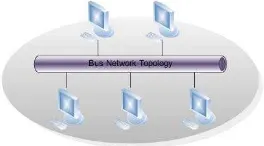
[image:22.595.239.371.627.700.2]In every network, had two types of typology which is physical topology and logical topology. In logical topology describes more to communication of component across physical topology. However, there are various types of physical topology network such as star topology, mesh topology, ring topology and bus topology. In this project bus topology are used for networking system .Bus topology is a single cable network or “trunk” or “backbone” and linked to all computers. The illustration of this topology was shown in Figure 2.1.
All the computer will connected to one single cable and affected the performance each computer. In this network, every computer cannot send data simultaneously. Only one computer can transmit data at a time. Others computers will be waiting to transport data. In addition, the data can‟t send in computer-computer interaction. Data will only commit to trunk cable not other computers in this network.
This network had been chosen because of it is easy to install, inexpensive, flexible and it‟s required less wires used. However, bus topology has their disadvantages such as it had a limitation of cable length and number of stations, when one node fails, the entire network will shut down and the executions of the network will fall due to increasing of node or computer.
2.2 Controlled Area Network (CAN)
Controlled Area Network (CAN) is a serial bus communication protocol that provides reliable, economic, and efficient link between devices to provide the distributed real time applications by using bit-wise deterministic collision- resolution mechanism [1]. Besides that, it also had high integrity serial bus system for networking intelligent devices as in standard vehicle in the network.
CAN Bus can be classed as a broadcast communication mechanism because of it node operating system. This is because all the nodes can „hear‟ the transmission, without exception. Furthermore, CAN is message oriented transmission protocol. It means, every message has its own message identifier and the whole network will define the priority of the message. [4]. Therefore, if two nodes send messages at a time, the one who higher priority will transmitted first followed by lower priority‟s message.
This transmission protocol will cause collision among the messages, and it‟ll be resolved by using bit-wise arbitration then allow the message to remain inviolate. In past, CAN Bus system are aim for automotive network system but nowadays, the CAN Bus is widely used in other sector such as automation.
6
addition, there are several reasons why CAN Bus system had been chosen to replace the old wiring system.
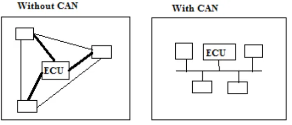
[image:24.595.160.454.236.362.2]In the past, most industries used point to point wiring system to connect electronic devices in vehicles. Due to improve on technology times by times, wiring system became more complicated, bulky, heavy and expensive. Then vehicle‟s weight will increase due to improved of the wiring system. By using CAN Bus, the wiring system can be scaled down.It can be represented as shown in Figure 2.2..
Figure 2.2: Network with CAN and without CAN
From Figure 1.1, it's shown that CAN Bus system only utilize a twisted cable to communicate with each other. Besides that, CAN Bus is contain several characters of large amounts of information, intuitive, high speed of responding, more accuracy and more stable display will had high demand in market [7]. Moreover, CAN Bus also had low cost due to lightweight network, wide broadcast communication, and priority system and had error checking capabilities.
Other features of CAN Bus had serial asynchronous Multi Master bus, transfer rate up to 1 Mbps, maximum bus length up to 40 m, unlimited number of nodes, 2032 different types of messages, 0 to 8 bytes information per data frame and have high safety level due to presence of mechanism for detection, notification and recovery faults.