PROJECT COMPLETION REPORT
FOR
(SHORT TERM) RESEARCH GRANT
ANALYTICAL STUDY OF LIGHT AND LIQUID
CRYSTALS REORIENTATION IN ANISOTROPIC
PHOTONIC CRYSTALS USING ONE-DIMENSION
FINITE DIFFERENCE TIME DOMAIN (FDTD) METHOD
Principal Researcher : Najmiah Radiah Binti Mohamad
Co-Researchers : 1. Chairulsyah Wasli (FKEKK)
2. Mohamad Zoinol Abidin Bin Abd. Aziz (FKEKK) 3.Azahari Bin Salleh (FKEKK)
4. Abd Shukur Bin Ja'afar : (FKEKK)
Project Code No.: PJP/2010/FKEKK (3D) S674
Report Submission Date : 23 September 2013
Department of
i
PJP/2010/FKEKK (3D) S674
ANALYTICAL STUDY OF LIGHT AND LIQUID CRYSTALS
REORIENTATION IN ANISOTROPIC PHOTONIC CRYSTALS
USING ONE-DIMENSION FINITE DIFFERENCE TIME
DOMAIN (FDTD) METHOD
NAJMIAH RADIAH BINTI MOHAMAD
RESEARCH CODE NO:
PJP/2010/FKEKK (3D) S674
Fakulti Kejuruteraan Elektronik dan Kejuruteraan Komputer
Universiti Teknikal Malaysia Melaka
ii
ACKNOWLEDGEMENT
First of foremost we would like to thank Allah for giving us the health, strength and patience to complete this research project successfully.
We would like to express a sincere gratitude to the Universiti Teknikal Malaysia Melaka (UTeM) for sponsoring this research project and giving us the opportunity to expand our knowledge in this research area. We also want to recognize the kind support received from the staffs of Faculty of Electronics and Computer Engineering and the personnel from the Centre for Research and Innovation Management (CRIM). Besides, we would like to express a sincere gratitude to Nagaoka University of Technology, Japan for providing the resources for this research.
iii ABSTRACT
ANALYTICAL STUDY OF LIGHT AND LIQUID CRYSTALS REORIENTATION IN ANISOTROPIC PHOTONIC CRYSTALS USING ONE-DIMENSION FINITE DIFFERENCE TIME DOMAIN (FDTD)
METHOD
(Keywords:Diffraction; Nematic liquid crystals; Birefringence; Anistropic Photonic
Crystals; Finite Domain Time Difference; Holography )
This study demonstrate diffractive light from an anisotropic photonic crystal (PCs) based on holographic polymer-dispersed liquid crystals (HPDLCs) that are fabricated using two-beam interference with various pitch and exposure energy. One of the most powerful approaches for the analysis of PCs structure is 2×2 Jones method, which is widely used for most simple cases. But, in case of anisotropic structures which more microscopically or complex, it cannot analyze with accuracy in this method. In this research, we have studied and analyzed the modulation of light and liquid crystal reorientation in one-dimension anisotropic PCs from HPDLCs using FDTD method. HPDLCs is modeling as a mixture of polymer and liquid crystals (LCs) that categorized as an anisotropic medium. FDTD method is directly solve Maxwell’s equation with less approximation, so this method can analyze more flexible and general approach for the arbitrary anisotropic media. As the results from FDTD simulation, Bragg diffraction is occurred when Q>10 and highest diffraction efficiency occurred at ±19 degrees (Bragg
angle) when incident beam is p polarization. Therefore, we can assumed the liquid crystal
is aligned parallel to the grating constant vector(n // k) from perpendicular alignment )
(nk at low exposure energy or wider pitch grating. Furthermore, by using FDTD
iv
Key Researchers:
Mdm. Najmiah Radiah Binti Mohamad (Head) Mr. Chairulsyah Wasli
Mr. Mohamad Zoinol Abidin Bin Abd. Aziz Mr. Azahari Bin Salleh
Mr. Abd Shukur Bin Ja'afar
E-mail: najmiradhi@utem.edu.my Tel. No.: 06-5552099
vi
3.2.10 TM PML ... 29
3.2.11 Impedance Matching Condition in PML ... 30
3.2.12 Courant stabilization condition ... 32
3.2.13 Incident light ... 33
3.2.13 Far-field calculation ... 34
CHAPTER IV RESULT AND DISCUSSIONS ... 35
4.1 Diffraction characteristic on anisotropic PCs based on HPDLC ... 35
4.2 Dependence of birefringence on grating constants ... 39
4.3 Liquid crystal reorientation ... 40
CHAPTER V CONCLUSION ... 43
vii
LIST OF FIGURES
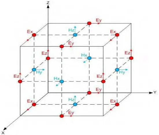
Figure 1.1 : Illustration of a standard Cartesian Yee cell used for FDTD ...4
Figure 1.2 : Flow Chart of the programming for FDTD Method………...5
Figure 2.1 : Classification of liquid crystal…… ... 7
Figure 2.2 : Director of liquid crystal ... 8
Figure 2.3 : Indicatrix of uniaxial crystal... 9
Figure 2.4 : Photonic crytals dimensional... 9
Figure 3.1: Calculation model for Coupled Wave Theory ... 13
Figure 3.2 : Time arrangement of electromagnetic field ... 16
Figure 3.3 : Electromagnetic field arrangements in TE FDTD ... 19
Figure 3.4 : Electromagnetic field arrangements in TM FDTDistogram ... 20
Figure 3.5 : Molecular coordinate system and laboratory coordinate ... 22
Figure 3.6 : Electromagnetic field arrangements of anisotropic medium...………...24
Figure 3.7 : Flow chart of TE and TM FDTD ... 25
Figure 3.8 : Normal incident from plane wave into the vacuum ... 26
Figure 3.9 : PML absorption condition ... 31
Figure 4.1 : Diffraction pictures of holographic PDLC when a) Q>10 and b) Q<10...35
Figure 4.2 : FDTD calculation model ... 36
Figure 4.3 : Diffraction characteristic when Q>10 and exposure energy is 800mJ/cm2...37
Figure 4.4 : Suggested anisotropic PCs ... 38
Figure 4.5 : Calculated dependence of diffraction efficiency on incident angle by FDTD method. ... 39
Figure 4.6 : Dependence of birefringence on grating constants ... 39
Figure 4.7 : Dependence of diffraction efficiency on polarization angle with different exposure energies. Grating constant is 1m ... 40
viii
LIST OF TABLES
Table 3.1 : Parameter of FDTD method ... 32 Table 4.1 : Relationship between grating constants and Q parameter value…..…...……35 Table 4.2: Birefringence of FDTD fitting parameters for each grating constant with
1
CHAPTER I
INTRODUCTION
1.1 Introduction
2 1.2 Problem Statement
These days there are a lot of interest in the simulation and analysis of the properties of photonic and optical devices such as PCs. Due to their complex structures that will not allow traditional calculation for light pass through them, FDTD has apparently is the solution to overcome the problem. FDTD method is a very general method to calculate the electromagnetic fields in a structure or arbiratary geometry. Furthermore, no mathematical approximation, high reliability and versatility calculation to explain the liquid crystal reorientation in PCs based on HPDLCs.
However, the calculation is a very challenging task and can effectively be performed by super computer. In addition, the commercial software for FDTD is expensive and we need to derive mathematical equation and run the programming using Fotran90 and Matlab. Therefore, the load to the computing time is long and large memory capacity is needed for accumulating cell size from nano to micro range although in one dimensional calculation. However, the calculation is very accurate since the FDTD method is direct discreatization of Maxwell’s equation for wave propagation such as light flow in isotropic or anistropic material. Typically, this method has been used widely in antenna and electromagnetic theory. It is not generally used in photonic because the target structural size or object is too large than the electromagnetic wavelength. Therefore, the load to the computing time is long and large memory capacity is needed. In recent years, improvement in the computer performance has encouraged FDTD method application in photonic.
1.3 Scopes of the Research
The scopes of this research are as the following:
3
2. The research were focused on high reliability and versatility calculation without mathematical approximation to explain the liquid crystal reorientation.
3. This research analyzed detailed structure for high diffraction efficiency depend to liquid crystal reorientation using the relationship between polarization and modulation of light in anisotropic PCs.
1.4 Objectives of the Research
The objectives of this research are:
1. To create one-dimensional FDTD method for high efficiency anistropic PCs.
2. To investigate the modulation of light in anisotopic PCs based on HPDLCs.
3. To explain and clarify how to control and manipulate the modulation of light depends on the reorientation and migration of the LCs.
1.5 Research Methodology
4
Figure 1.1 : Illustration of a standard Cartesian Yee cell used for FDTD
Nematic liquid crystal (NLCs) is assumed as the material which has uniaxial anisotropy medium consist of extraordinary refractive index ne and ordinary refractive
index no respectively. The director N of NLC can be defined in laboratory coordinate and
the dielectric tensor can be calculated by coordinate conversion of director direction. In electromagnetic field arrangement, the electric field, E and electric displacement, D is
5
Figure 1.2 Flow Chart of the programming for FDTD Method
6
CHAPTER II
LITERATURE REVIEW
2.1 Liquid Crystals
7
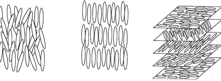
a) nematic liquid crystal b) smectic liquid crystal c) cholesteric liquid crystal
Figure 2.1 Classification of liquid crystal
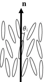
In this research we used nematic liquid crystal. The molecules are rodlike with their long axes aligned approximately parallel to one another but random at molecules position relation. Microscopically, each molecule of liquid crystal is aligned in various direction and not completely parallel as shown in Figure 2.2. However, macroscopically the molecules are overall suitable for a certain direction which called director. Thus at any point of the molecules, we can define a vector n to represent the preferred director in the immediate neighbourhood of the point. In a homogeneous nematic liquid crystal, the director is constant throughout the medium. In an inhomogeneous nematic liquid crystal, the director n can change from point to point and in general, a function of space(x,y,z). To determine the overall distribution of the molecules direction, it can be defined using order parameter as
2
3 cos 1
1 2
i
S
(2.1)
θi is represent the angle between long axis of individual molecule and the director n,
8
Figure 2.2 Director of liquid crystal
2.2 Birefringence (Optical anisotropy)
The main characteristic of liquid crystal is its anisotropic refractive index similar to uniaxial anisotropic crystal. Liquid crystal and uniaxial anisotropic crystal possesses two difference refractive indexes which consist of ordinary refractive index of
n
oandextraordinary refractive index of
n
erespectively. The ordinary refractive index is for lightwith electric field polarization perpendicular to the director (long axis)
n
o
n
, and theextraordinary refractive index is for light with electric field polarization parallel to the
director (long axis)
n
e
n
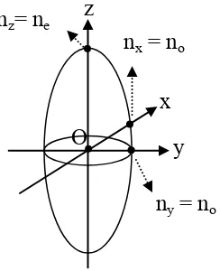
. Birefringence is defined as indicatrix as shown in Figure 2.3. Therefore, it can be defined in equation as9
where nx, ny, and nz are main refractive indexes, nx=ny≡no are represent the ordinary
refractive index and nz≡ne are represent the extraordinary refractive index. For example,
refractive index becomes equal in all direction when the light propagates in z direction which is well known as optical axis. In other direction, electric field vector of the light wave will passes point O and refractive indices are divided into different two value.
Figure 2.3 Indicatrix of uniaxial crystal
2.3
Photonic Crystalsa) b) c)
Figure 2.3 Photonic crystals dimensional a) periodic in one dimension which is discovered by Lord Rayleigh; b) periodic in two dimension that demonstrated by Thomas Krauss and c) periodic crystals periodic in three dimension.
y z
x nz= ne
ny = no
nx = no
10
The periodicity in one, two or multi-dimensional are able to confine, control and manipulate the propagation of light in PCs based on Bragg diffraction on lattice planes. There is a band of frequencies which light propagation in the PCs is forbidden. It is called photonic band gap (PBG or stop band). A complete PBG occurs when a range of frequencies is forbidden for every state of polarization and propagation direction. Because of these properties, a wide variety of applications are interested such as displays, optical wave-guides, optical data storage, switches, lasers, and sensors [1-2].
After the proposal by Yablonovitch in 1993, fabrication of PCs has been investigated intensively [5]. Various techniques to fabricate PCs such as electron-beam lithography, self-multiphoton polymerization, semiconductor micromatching, nanoprinting, holographic lithography, self assembling of microparticles and cross grating have been demonstrated with different levels of success[3-4]. In 1995, Russel et. al has successfully constructed hexagonal lattice of air holes in silica glass. This
discovery showed PCs possessed two dimension photonic band structures which is the starting point of Photonic Crystal Fiber (PCF) research development. It is quite different from those of conventional fiber optics but still using Total internal reflection (TIR). Using PBG as a new theory of PCF, there are two advantages. There are a big change of effective refractive index of clad depend to the wavelength and the difference refractive indices of core and clad are bigger than conventional fiber optics. Nevertheless, there is a lot of problems of PCF fabrication before realize it as application.
11
12
CHAPTER III
METHODOLOGY
3.1 Coupled Wave Theory
A coupled wave analysis is given of the Bragg diffraction of light by thick hologram gratings, which is analogous to Phariseau's treatment of acoustic gratings and to the dynamical theory of X-ray diffraction. The theory remains valid for large diffraction efficiencies where the incident wave is strongly depleted when Q>10. It can be applied to transmission holograms and to reflection holograms.
This theory assumes monochromatic light incident on the hologram grating at or near the Bragg angle and polarized perpendicular to the plane of incidence. Only two significant light waves are assumed to be present in the grating, the incoming “reference” wave R and outgoing “signal” wave S. Only these two waves obey the Bragg condition at
least approximately, the other diffraction order violate the Bragg condition strongly and are neglected. They should be of little influence on the energy interchange between S and R.
Figure 3.1 shows the model of a hologram grating which is used for this research. The z-axis is chosen perpendicular to the surfaces of the medium, the x-axis in the plane of incident and parallel to the medium boundaries and the y-axis perpendicular to the paper. The fringes planes are oriented perpendicular to the plane incidence and slanted with respect to the medium boundaries at an angle . The grating vector K is oriented
perpendicular to the fringe planes and is length K =
2 , where is the period of
13
Figure 3.1 Calculation model Coupled Wave Theory
the grating. The same average dielectric constant is assumed for the region inside and outside the grating boundaries. The angle of incidence measured in the medium is.
In case of no slant
2
and Bragg condition is obeyed, diffraction efficiency can be
calculated by well known equation as below [26].
(3.1-1)
where (3.1-2)
and (3.1-3)
is the wavelength of incident beam, n is amplitude of index modulation,
14
is the sample thickness, is the angle of incident in a sample, is the Bragg angle, and is the deviation from the Bragg angle.
3.2 Finite Domain Time Different (FDTD) method [12]
3.2.1 Introduction
In 1966, Kane Yee originated a set of finite-difference equations for the time-dependent Maxwell’s curl equations to calculate the electromagnetic fields in discrete space and time directly. This numerical electromagnetic analytical method is well known as FDTD method. Using both electric field, E and magnetic field, H information, the
solution is more robust than using either electric field or the magnetic field alone with a wave equation. Moreover, there is no mathematical approximation and high versatility that various calculation models can be calculated. Typically, this method has been used widely in antenna and electromagnetic theory. However, it is not generally used in optic because the target structural size or object is too large than the electromagnetic wavelength. Therefore, the load to the computing time is long and large memory capacity is needed. In recent years, improvement in the computer performance has encouraged FDTD method application in optics.
15 density, J is electric current density and ρ is chargedensity.
3.2.2 Basic concept
In FDTD method, calculation area is taken to enclose wave source and scattering substance. The calculation area is divided into unit cell as shown in Figure 1.1. Next, by applying Yee algorithm, formulated Maxwell equation is calculated to all cells. A key to Yee algorithm is the components of E and H (Ex,Ey,Ez,Hx,Hy,Hz) are staggered and
spatially offset from one another. Therefore, Maxwell equation can be solved in the numerical value using first central-difference.
In Yee Algorithm, E and H are offset in time by 1/2 time step using a leapfrog time-stepping technique. The leapfrog time-stepping algorithm is explicit and simultaneous equations can be avoided. In Figure 3.2, Δt is a time step and x is assumed to be a paragraph where time is shown. The electric field is assumed to allocate at integer order of time t=(n-1)Δt、nΔt、(n+1)Δt…, while magnetic field is
t=(n-1/2)Δt、(n+1/2)Δt… In an actual calculation, the electric field En is calculated from electric field En-1 and t=(n-1) Δt of magnetic field Hn-1/2, then Hn-1/2 and En to calculate