i
MODELING PLANAR INVERTED F ANTENNA BASED ON 3D FINITE DIFFERENCE-TIME DOMAIN (FDTD) METHOD IN GRAPICHAL USER
INTERFACE (GUI) FOR RADIATION PATTERN EVALUATION.
NUR AZILA BINTI AWANG MD ISA
This Report is Submitted In Partial Fulfillment of Requirement for Award of Bachelor of Electronic Engineering (Telecommunication Electronics) With Honour
Faculty of Electronics and Computer Engineering Universiti Teknikal Malaysia Melaka
v
It is only befitting that I dedicated this humble work to the noble and illustrious prophet, Muhamad SallallahuAlaihiWasallam, addressed by Allah SubhanahuWata’ala as the “Unlettered” Prophet, yet, the Master of the most extensive knowledge, foretold in previous scriptures, and the Mercy for the Worlds.
vi
ACKNOWLEDGEMENT
Alhamdulillah, all Praise thank to Allah SWT the Almighty for giving me the Rahmah to finish my Final Year Project successfully.
Secondly, I would like to express my sincere gratitude to all these who gave me the possibility to complete this PSMII. I am deeply indebted to my supervisor Mr Fauzi Bin Mohd Johar whose help, stimulating suggestions and encouragement helped me in all the time of research for and writing of this thesis. My sincere gratitude and many thanks goes to him for his endless support and ideas, during which he has been patiently supervising my progress and encouraged me to do this project the right way.
My sincere thanks also to friends under the same supervisor that Siti Nursyuhada Binti Mat Nasir, Nazrul Affendi Bin Che Ibrahim, Shafiq Izwan Bin Yahaya, and Mohd Shahril Bin Abdul Razak because they helped me a lot during the course of processes and PSMII well as the implementation thesis. They give a lot of ideas and also motivate me to complete my PSMII.
vii
ABSTRACT
viii
ABSTRAK
ix
TABLE OF CONTENTS
CHAPTER CONTENT PAGE
PROJECT TITLE
STATUS REPORT FORM ii
STUDENT DECLARATION iii
SUPERVISOR DECLARATION iv
DEDICATION v
ACKNOWLEDGEMENT vi
ABSTRACT vii
ABSTRAK viii
TABLE OF CONTENTS ix
LIST OF FIGURES xiii
LIST OF APPENDIXS xv
I INTRODUCTION 1
1.1 PROJECT OVERVIEW 1
1.2 OBJECTIVES 2
1.3 PROBLEM STATEMENTS 2
1.4 SCOPE OF WORKS 4
1.4.1 Understanding Finite-Difference Time- Domain (FDTD) algorithm
x
1.4.2 Familiarize Finite-Difference Time- Domain (FDTD) Program
5
1.4.3 Antenna Design in FDTD 6 1.4.4 Developed Graphical User
Interfaces(GUI)
7
1.4.5 Simulate using FDTD 8
II LITERATURE REVIEW 9
2.1 FINITE-DIFFERENCE TIME-DOMAIN(FDTD) 9 2.1.1 Fundamental of FDTD
2.1.2 Advantages of FDTD
11 15 2.1.3 Finite-Difference Time-Domain
(FDTD) Equations
16
2.1.3.1 Scalar Maxwell Equation for 3D FDTD
16
2.1.3.2 Disretization of Maxwell’s in time and space 3D curl equation (FDTD)
17
2.1.3.3 FDTD Sources Active Lumped Element
19
2.1.3.4 Convolutional Perfectly Matched Layer Regions and Associated Field Updates for a 3D domain
21
2.2 NUMERICAL STABILITY 34
2.3 ABSORBING BOUNDARY CONDITION 2.3.1 Perfectly Matched Layer (PML) 2.3.2 Convolution Perfect Matched Layer (CPML)
xi
2.4 PERFECT ELECTRIC CONDUCTOR (PEC) 39
2.5 NEAR FIELD FAR FIELD (NF-FF) 39
III ANTENNA 41
3.1 INTRODUCTION 41
3.2 TYPES OF ANTENNA 42
3.2.1 Microstrip Antenna 42 3.2.1.1 Planar Inverted F Antenna 43
3.3 PARAMETERS OF ANTENNA 45
3.3.1 Radiation Pattern 45
3.3.2 Directivity 49
IV METHODOLOGY 51
4.1 PROJECT METHODOLOGY 51
4.2 FDTD PROGRAM 53
4.3 MATLAB GRAPHICAL USER INTERFACE (GUI)
55
V RESULT AND ANALYSIS 58
5.1 PROJECT RESULT 58
5.1.2 Simulation Radiation Pattern Result 60 5.2 SIMULATION RESULT ON GRAPHICAL USER
INTERFACE (GUI)
xii
5.3 COMPARISON RESULT BETWEEN DIFFERENT FREQUENCY
64
VI CONCLUSION AND SUGGESTION 67
6.1 CONCLUSION 67
6.2 SUGGESTION AND FUTURE WORKS 68
xiii
LIST OF FIGURE
NO OF FIGURE TITLE PAGE
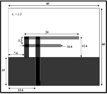
1.1 The design for a planar inverted F antenna (Top view)
6
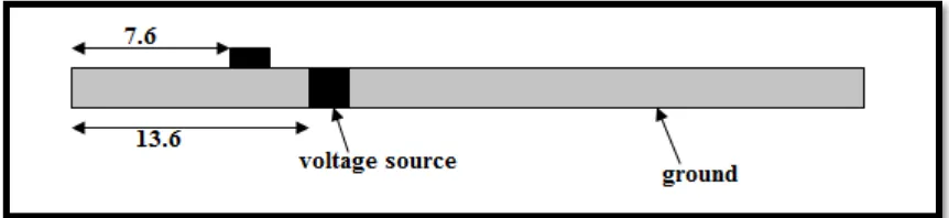
1.2 The design for a planar inverted F antenna (Side view)
7
2.1 Yee cell 10
2.2 Position of the electric fields in yee’s scheme 12 2.3 Approximation of derivative of f(x) at x by finite
difference: central differences
13
2.4 An FDTD problem space and the objects approximated by snapping to cells
14
2.5 Field component around Ex(i,j,k) 14
2.6 Field component around Hx(i,j,k) 15
2.7 The three-dimensional problem space is truncated by absorbing boundaries
37
2.8 The CPML on the plane boundary 38
3.1 The transitional structure between free space and a guide
42
xiv
3.3 Omnidirectional antenna pattern 47
3.4 E-plane pattern 48
3.5 H-plane pattern 48
3.6 Half wavelength 48
3.7 One wavelength 49
3.8 Two-Dimensional directivity pattern 50
3.9 Three-Dimensional directivity pattern 50
4.1 Flowchart of project methodology 52
4.2 Program flowchart of FDTD procedure 54
4.3 The icon ‘GUIDE’ in MATLAB software 55
4.4 The output for choose to create GUI 56
4.5 The output for create new GUI 56
4.6 The design of GUI 57
5.1 The dimensions of planar inverted F antenna 59 5.2 Result from model planar inverted F antenna 59 5.3 Structure of the FDTD Planar Inverted F antenna 60 5.4 Radiation pattern of planar inverted antenna for
frequency 2.4 GHz
61
5.5 Radiation pattern of planar inverted antenna for frequency 5.8 GHz
62
5.6 Simulation Layout on GUI 63
5.7 Result Layout on GUI 64
5.8 Comparison radiation pattern for different
frequency of planar inverted F antenna in xy-plane
65
5.9 Comparison radiation pattern for different
frequency of planar inverted F antenna in xz-plane
66
5.10 Comparison radiation pattern for different
frequency of planar inverted F antenna in yz-plane
xv
LIST OF APPENDIX
NO OF APPENDIX
TITLE PAGE
A Coding for Main FDTD 72
B Coding define geometry 73
C Coding define problem space and parameter 74 D Coding define sources and lumped element
components
76
CHAPTER I
INTRODUCTION
1.1 PROJECT OVERVIEW
2
transformation technique and Fast Fourier Transformation ( FFT) will be implemented. By changing several parameter of the antenna, radiation pattern can be visualized and studied. Besides that to verify antenna radiation pattern from Finite Different Time Domain (FDTD) software it will be compared to commercial software either CST or HFSS.
1.2 OBJECTIVES
The objectives of this project are
1) To model planar inverted F antenna using 3D Finite-Different Time-Domain (FDTD).
2) To implement MATLAB programming in planar inverted F antenna modeling. 3) To analyze the radiation pattern of planar inverted F antenna.
The main objective for this project to model planar inverted F antenna with designs the software where to develop 3D finite-difference time-domain (FDTD) in graphical user interface (GUI) for radiation pattern evaluation.
1.3 PROBLEM STATEMENTS
3
if does not get a best result. The antenna is excited by a voltage source, and sampled voltage and a sampled current are defined on and around the voltage source to form an input port. So that, Finite-Different Time-Domain (FDTD) is used for solve the Maxwell equation. For the reason is, it will easier to modeling than implement experimental. Thus, it reduce cost, time and can test for different planar inverted F antenna dimension.
4
1.4 SCOPE OF WORKS
1.4.1 Understanding Finite-Difference Time-Domain (FDTD) algorithm
5
1.4.2 Familiarize Finite-Difference Time-Domain (FDTD) Program
The starting point for the construction of an FDTD algorithm is Maxwell's time-domain equations. The differential time-time-domain Maxwell's equations needed to specify the field behavior over time are. Study application of Maxwell’s equations, for this project only use Ampere’s Law and Faraday’s Law. The equations are :
1) To study application of Ampere Maxwell’s Law
J H t
D
− × ∇ = ∂
∂ (1.4.2a)
2) To study application of Faraday Law
M E t
B
− × −∇ = ∂ ∂ (1.4.2b)
Where the symbols are defined as : H = magnetic field (A/m)
D = electric flux density (C/m2) J = electric current density (A/m2) E = electric field (V/m)
6
1.4.3 Antenna design in FDTD Dimensions in mm
Substrate thickness = 0.787mm
[image:21.612.137.511.224.552.2]Strip widths =2.4mm
7
Figure 1.2 : The design for a planar inverted F antenna Side view
1.4.4 Developed Graphical User Interfaces (GUI)
In this project, Graphical User Interface is used. In computing, a graphical user interface is a type of user interface that allows users to interact with electronic devices using images rather than text commands. A Graphical User Interface (GUI) represents the information and actions available to a user through graphical icons and visual indicators such as secondary notation, as opposed to text-based interfaces, typed command labels or text navigation. The actions are usually performed through direct manipulation of the graphical elements.
There are several compelling arguments for using MATLAB as a GUI development tool. The important to develop Graphical User Interface (GUI) in MATLAB is:
1) High-Level Script Based Development
8
2) Seamless Integration with Existing MATLAB Computational Power
May already be a committed MATLAB user and have libraries of functions and scripts for solving specific problems related to field or perhaps have acquired scripts and functions through the science and engineering community. Building Graphical User Interface (GUI) using MATLAB means that all the code have developed to solve complex problems may be directly used within GUI.
3) Operating System Independent GUI Applications
MATLAB currently supports operating systems such as Solaris (UNIX), MS Windows, Linux, and Mac OS-X and this allows considerable flexibility for code development. Since M-file scripts are not compiled, they may be executed using MATLAB that runs on any operating system supported. This is also true for GUI application development with a few exceptions for some properties.
4) User Interactivity and Real-time Measurements
Although M-file scripts and functions are excellent for solving many problems, there are often situations where user interactivity with the application is integral for understanding or solving a particular problem. Some examples of where a GUI interface can help the user interact efficiently with an application are listed below:
Video applications Audio Signal Processing
Communications Signal Processing Simulation of Complex Systems Animation of 2D or 3D Graphical Data
CHAPTER II
LITERATURE REVIEW
This chapter contains the literature review theoretical concept that applied in this project. It contains the information gathering of the project in order to complete whole project. The main source is book and other sources, which is journals and articles obtained from internet.
2.1 FINITE-DIFFERENCE TIME-DOMAIN (FDTD)