DEVELOPMENT AN AM RADIO BOARD
FOR LABWORK BENG 2413
SITI SUHAILA BTE SALEHAN
POWER ELECTRONICS AND DRIVES
“I hereby declare that I have read through this report and found that it has comply the partial fulfillment for awarding the degree of Bachelor Electrical Engineering
(Power Electronics and Drives)”
Signature :
Supervisor‟s Name : Mr. Hyreil Anuar Bin Kasdirin
ii
DEVELOPMENT AN AM RADIO BOARD FOR LABWORK BENG 2413
SITI SUHAILA BTE SALEHAN
A report submitted in partial fulfillment of require ments for the degree of Bachelor
In Electrical Engineering (Power Electronic and D rive)
Fakulti Ke juruteraan Elektrik
UNIVERSITI TEKNIKAL MALAYSIA MELAKA
iii
“I hereby declare that this report is a result of my own work except for the excerpts that have been cited clearly in the references”
Signature :
Name : Siti Suhaila Binti Salehan
iv
v
ACKNOWLEDGEMENT
First of all, A am grateful because I was given a change to take part in this project. This is a wonderful opportunity for me to using my skills in both the programming and hardware area.
In this segment, I wanted to thank is my project supervisor, Mr. Hyreil Anuar Bin Kasdirin for allowing me to do this project. He had given me some idea on how to do our project and also in writing this report. He also had given inneridea in completing this project. Through his guidance, I was able to complete this project as expected.
vi
ABSTRACT
vii
ABSTRAK
Projek ini menerangkan rekabentuk dan penghasilkan AM radio board trainer yang
boleh digunakan oleh pelajar untuk kerja amali BENG 2413. Hasil rekabentuk projek ini, pelajar dapat lebih memahami teori dan kerja amail berkaitan dengan matapelajaran ini. Pada ketika ini, FKE tidak menyediakan AM radio board trainer yang boleh digunakan
oleh pelajar untuk melaksanakan kerja amali BENG 2413. Oleh itu, projek ini dibagunkan dengan beberapa penambahbaikan di mana sesetengan aplikasi pada trainer boleh dikawal
oleh PC. Objektif utama projek ini adalah menghasilkan AM radio board trainer sebagai Computer Based Trainer(CBT). Projek ini mengandugi litar Penerima AM Radio dimana
ia mengandungi 5 peringkat iaitu penala, penguat isyarat radio, pengesan, penguat audio dan alat pembesar suara digunakan dalam projek ini. Dalam projek ini, perisian Visual Basic 6.0 digunakan sebagai Graphical User Interface (GUI). Masukan sesiri RS232 dan
pemacu sesiri MAX 232 digunakan sebagai penghubung diantara komputer dan perkakasan. Penghasilan AM radio board trainer ini sebagai CBT dapat digunakan oleh
pelajar-pelajar FKE untuk kerja amali BENG 2413.
viii
2.2 AM Radio Tools 9
TABLE OF CONTEN TS
CHAPTER TITLE PAGES
SUPERVISOR VERIFICATION i
TITLE PAGE ii
DECLARATION iii
DEDICATION iv
ACKNOWLEDGEMENT v
ABSTRACT vi
ABSTRAK vii
TABLE OF CONTEN TS viii
LIST OF TABLES xi
LIST OF FIGURES xii
LIST OF SYMBOLS xiv
LIST OF APPENDIXES xv
1.0 INTRODUCTION
1.0 Introduction 1
1.1 Objectives of the project 2
1.2 Problem Statement 2
1.3 Scope of the Project 3
1.4 Organization of the Report
1.5 Summary
4 4
2.0 THEOR Y AND LITERATURE REVIEW
2.0 Introduction 5
2.1 AM radio operation 5
2.1.1 Principle of Amplitude Modulation 6
2.1.2 Tuned Radio-Frequency Receiver 7
ix
2.2.1 Antenna 9
2.2.2 Tuner 10
2.2.3 RF Power Amplifier 10
2.2.4 Detector
2.2.5 Audio Amplifier
10 10
2.2.6 Speaker 11
2.3 Microsoft Visual Basic Programming Tool 11
2.3.1 Visual Basic 6.0 versus Other Version of Visual Basic
12
2.3.2 Drawing the User Interface and Setting Properties 12
2.4 Communication Interface Devices 15
2.4.1 Serial Communication Interface RS-232 15
2.4.2 PIC Microcontroller Start Up Kit (SK40B) 17
2.5 Comparison of an another AM radio board trainers 19
2.5.1 A Simple Radio Receiver 19
2.5.2 Educational and Training Equipment, Module KL-93002
20
2.5.3 AM Transmitter and Receiver System
Module KL-900-C
21
2.5.4 AM and FM Superheterodyne Radio Trainer, Module
ERT-AFS
22
2.6 Summary 23
3 METHODOLOGY
3.0 Introduction 24
3.1 Work Plan of the Project 24
3.1.1 Tasks in project planning 27
3.1.2 Project Design and Project Construction 28
3.1.3 Project Assembling and Project Testing 29
3.2 Hardware Requirements in Development of the AM
Radio Trainer
29
3.2.1 AM Radio Transmitter (AM Modulator) 30
x
3.2.3 PIC Microcontroller Start Up Kit as interface circuit 34
3.3 Software Requirement in Development of the AM
Radio Trainer
36
3.3.1 Multisim 2001 37
3.3.2 Visual Basic 6.0 Software 38
3.3.3 Proteus 7 Professional 39
3.4 Summary 40
RESULT AND DISCUSSION
4.0 Introduction 41
4.1 Results for Simulation Part 41
4.1.1 Simulation Result for RF Amplifier Circuit 42
4.1.2 Simulation Result for Audio Amplifier Circuit 44
4.1.3 Detector Circuit 46
4.2 Result for Graphical User Interface 48
4.3 Result for Hardware Part 50
4.4 Experiment Result and Analysis 51
4.4.1 Experiment 1: RF Amplifier 51
4.4.2 Experiment 2: Audio Amplifier 52
4.4.3 Experiment 3: AM Modulation 53
4.4.4 Experiment 4: AM Receiver (Demodulation) 56
4.4.5 Interface Communication 57
4.5 Problem Encountered and Troubleshooting 58
4.6 Discussion 59
4.7 Summary 59
CONCLUSION AND RECOMMENDATIONS
5.0 Introduction 60
5.1 Conclusion 60
5.1 Recommendation 61
REFERENCES 62
xi
LIST OF TABLE
TABLE TITLE PAGE
2.1 Function descriptions of 9-pin connector RS-232 17
4.1 Reading taken from RF Simulation Circuit 42
4.2 Reading taken from Audio Amplifier
simulation Circuit
xii
LIST OF FIGURE
FIGURE TITLE PAGE
2.1 AM Generation 6
2.2 Tuned Radio Frequency (TRF) Operation 7
2.3 Radio frequency receiver block diagram 8
2.4 AM Demodulation 8
2.5 AM Demodulation with complete detector 9
2.6 Main window of Visual Basic 13
2.7 Form Window of Visual Basic 13
2.8 Toolbar and Properties Window 14
2.9 Form Layout Window and Project Window 14
2.10 9-pin female connector 16
2.11 Board Layout of SK40B 17
2.12 A Simple Radio Receiver 19
2.13(a) Audio Generator 21
2.13(b) AM Trainer 21
2.14 AM Transmitter and Receiver trainer module
KL-900C
22
2.15 Radio Trainer Module ERT-AFS 22
3.1 Overall Project Flow Chart 26
3.2 Overall Block Diagram of the AM radio trainer 29
3.3 Block diagram of AM Modulator 30
3.4 AM Modulator circuit 31
3.5 Complete Block Diagram of AM Radio Receiver 32
3.6(a) Tuner Circuit 33
3.6(b) RF Amplifier Circuit 33
3.6(c) Detector Circuit 33
3.6(d) Audio Amplifier Circuit 33
xiii
3.7 Block Diagram of PIC Microcontroller Start up Kit 35
3.8 PIC Microcontroller Start up Kit circuit 36
3.9 Multisim user‟s interface 37
3.10 Microsoft Visual Basic front page 39
3.11(a) Schematic Diagram 40
3.11(b) PCB layout 40
4.1 RF Amplifier Simulation Circuit 42
4.2(a) Input Signal (Vin) 43
4.2(b) Output Signal (Vo) 43
4.3 Audio Amplifier Simulation Circuit 44
4.4(a) Input waveform 45
4.4(b) Output Waveform VR=0% 45
4.4(c) Output Waveform VR=30% 46
4.4(d) Output Waveform VR=70% 46
4.5 Detector Simulation Circuit 46
4.6(a) AM input signal 47
4.6(b) Output signal after detector 47
4.7 Graphical User Interface (GUI) for AM trainer 48
4.8 AM Radio Transmitter (AM Modulator) on PCB 50
4.9 AM Radio Receiver (Demodulator) on PCB 50
4.10(a) Input signal for RF amplifier 51
4.10(b) Output signal for RF Amplifier 52
4.11(a) Carrier input signal capture from oscilloscope 53
4.11(b) Audio input signal capture from oscilloscope 53
4.11(c) AM output signal 54
4.12 Over modulation waveform 55
4.13 Spectrum of AM signal 55
4.14 Amplitude Demodulation 56
xiv
LIST OF SYMBOL
AC Alternating Current
AM Amplitude Modulation
CB Citizens Band
CBT Computer Based Trainer
DC Direct Current
DCE Data Communication Equipment
GUI Graphical User Interface
PC Personal Computer
PCB Print Circuit Board
PIC Peripheral Interface Controller
RF Radio Frequency
TRF Tuned Radio Frequency
xv
LIST OF APPENDICES
NO TITLE PAGE
A Project Planning 64
B Learn Visual Basic 6.0 65
C Datasheet MC1496 68
D Datasheet MAX 232 72
xvi
CHAPTER 1
INTRODUCTION
1.0 Introduction
An AM radio board trainer is a device or trainer that it is developed as Computer Based Trainer (CBT). The development of this trainer could be used for student to have better understanding regarding the fundamental theory of BENG subject by practical work. The combination between fundamental theory and practical work during lab section give student easier to understand the subject through comparison between both.
In this project, there are 3 main parts to be include that is hardware and software part and also integration between both. The hardware part is divided by AM Radio Transmitter (AM Modulation), AM Radio Receiver (Demodulator circuit) and integration circuit. Meanwhile, software part is focus on design Graphical User Interface and also simulation process. The interface between PC and hardware is completed by serial port RS 232 and serial driver MAX 232.
xvii
1.6 Objectives of the project
The development of this project is to archive the following objectives:
i. To develop an AM radio board trainer as a Computer Based Trainer (CBT).
ii. The product development of this project can be used for the student to have better understanding regarding the fundamental theory of BENG subject.
iii. To design Graphical User Interface (GUI) using Visual Basic software to give more understanding and explore the function of an AM radio.
1.7 Proble m State ment
An Amplitude modulation (AM) topic is including in subject communication (BENG 2413). Suitable equipment or trainer is needed in order to help student learn and understand overall about an AM topic by practical work. At present, an AM radio trainer is not exists at Faculty of Electrical Engineering (FKE) which can be implementing by student for practical work in subject communication. So, this project is focus to develop and design an AM radio board for labwork of BENG 2413 which some improvement. The advantages of this trainer to another trainer that already exist at market are:
i. This trainer has two functions as AM modulation and AM radio receiver (demodulator) at the same board.
ii. The trainer is Computer Based Trainer (CBT) which it is interface between hardware part and PC through Visual Basic software.
xviii
1.8 Scope of the Project
For this project, new AM radio board panels as a Computer Based Trainer (CBT) will be developed. The trainer will be implementing by student for labwork of BENG 2413. The AM radio board used a basic an AM radio circuit which is consists of 5 stage; tuner, RF amplifier, detector, audio amplifier and speaker. It uses Visual Basic 6.0 software to control the AM frequency on the AM radio board. The AM radio board will be interface to PC using RS-232 cable. The data from PC will be transmitting to the controller MAX 232 using RS 232 cable. The AM radio board consists of speaker to listen the AM radio frequency and the output can be observed by using oscilloscope.
The project final result;
At the end of this project, an AM radio board panel as a Computer Based Trainer (CBT) had been designed. For this purpose, the AM radio board is able to interface to PC and control the AM radio frequency using by PC with Visual Basic 6.0 software. As an AM radio circuit on AM radio board panel, it needs to be function and the output frequency will be observe using by oscilloscope to make student easier to study and understand the AM radio topic.
The scope of this project:
i. For this project, a new AM radio board panel as a Computer Based Trainer (CBT). ii. It uses Visual Basic 6.0 software to design Graphical User Interface (GUI).
iii. The AM radio board will be interfaces to PC using serial port RS-232 cable and the data will be transmitting to the controller MAX 232 through it.
xix
1.9 Organization of the Report
This thesis is divided into 5 chapters. Each of the following paragraphs generally described the contents of each chapter.
Chapter 1 explained the objectives and problem statements of this project. It also consists of explanation the scope of this project.
Chapter 2 gives general description and overview of the theory of AM radio operation, software development and interface device. Some of literature review on AM radio trainer such as application, and advantages is also discussed in this chapter.
Chapter 3 discussed the process development of this project. The description of work plan, software and hardware used and also interface circuit. Part by part of hardware development is also briefly discussed in this chapter.
Chapter 4 shows the result, analysis and discussion of this project. Simulated and measurements result are analyzed before the analytical comparison take places.
Chapter 5 gives a summarized work and conclusion for overall of this project. Suggestion for future improvements and advancements of this project also discussed.
1.10 Summary
xx
CHAPTER 2
THEOR Y AND LITERATURE REVIEW
2.0 Introduction
An AM radio trainer is device that is developed to studying process through practical work section. Combination of the fundamental theory and practical work is more efficiency in give student easier understands about the AM radio topic. In order to develop this project, it is necessary to have strong background knowledge and fundamental concepts and theory about the communication system. This chapter introduced some of these fundamental concepts and an idea about the AM radio trainer from previous design.
2.1 AM Radio Operation
A communication link consists of three components: the transmitter, the channel, and the receiver. The transmitter element processes an information signal in order to produce a signal most likely to pass reliably and efficiently through the channel. This usually involves coding of the information signal to help correct for transmission errors, filtering of the signal to constrain the occupied bandwidth, modulation of a carrier signal by the information signal, and power amplification to overcome channel losses.
xxi
The receiver function is principally to reverse the modulation processing of the transmitter in order to recover the transmitted information signal, and attempts to compensate for any signal degradation introduced by the channel. This will normally involve amplification, filtering, demodulation, and decoding and in general is a more complex task than the transmit process.
2.1.1 Principle of Amplitude Modulation
Amplitude modulation is one of the earliest methods for transmitting a signal over a distance. Audio frequencies range from 0 to 20KHz but these frequencies do not radiate off metal antennas as well as radio frequencies (RF) in the high KHz range. So a RF oscillator is used to create the carrier frequency that is subsequently amplitude modulated with the audio, hence the name AM. The receiver is responsible for tuning in a statio n then demodulating the signal simply by extracting the audio from the carrier.
The amplitude of the signal is basically the vertical lengths of a sinusoidal and the amplitude can be changed by modulating the audio onto the carrier over time. The figure 2.1 below show demonstrates this concept. A signal can be understood in time domain or frequency domain. The figure 2.1 below is in the time domain because it shows a sinusoidal over time and the modulated signal has changing amplitudes over time.
xxii
Amplitude modulation is a relatively inexpensive, low-quality form of modulation that is used for commercial broadcasting of both audio and video signal. Amplitude modulation is also used for two-way mobile radio communications such as citizens band (CB) radio.
2.1.2 Tuned Radio-Frequency Receiver
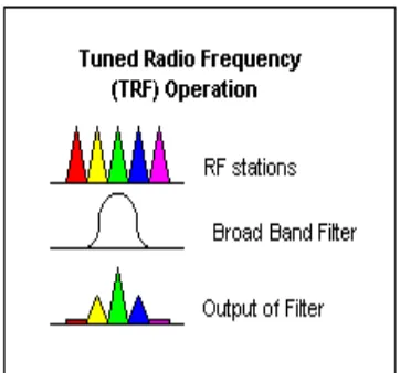
The Tuned Radio Frequency (TRF) radio receiver is one of the oldest receiver designs that was popular in the 1910s to 20s. The basic idea was to simply use a LC tuner to select a station, but there are many problems with this approach. At the time, triodes did not have very good amplification gain so several amplification stages were needed. Second, as mentioned earlier the LC circuit in practice is generally a broad bandpass filter and will pass through a few adjacent stations as demonstrated in the animation show in figure 2.2 below:
Figure 2.2: Tuned Radio Frequency (TRF) Operation
xxiii
Figure 2.3: Radio frequency receiver block diagram
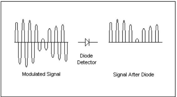
2.1.3 Demodulator
The earliest radio receiver was simply made with an antenna, a detector and earphones. The detector serves the purpose of extracting the audio from the modulated carrier and often does so by allowing current only in one direction. The diode is the simplest device that allows current in one direction. However, only allowing the positive edges of the modulated signal to pass through to the audio stage will produce high frequency noises and can be visualized in the following figure.
Figure 2.4: AM Demodulation