FOR TENNIS BALL MACHINE
KHAIRUL AMZAR BIN MOHD KASSIM
SUPERVISOR DECLARATION
“I hereby declare that I have read this thesis and in my opinion this report is sufficient in terms of scope and quality for the award of the degree of
Bachelor of Mechanical Engineering (Automotive).”
Signature: ……….
Supervisor: ……….
DESIGN AND FABRICATION OF THROWER MECHANISM FOR TENNIS BALL MACHINE
KHAIRUL AMZAR BIN MOHD KASSIM
This report submitted in partial fulfillment of the requirement for the award of
Bachelor of Mechanical Engineering (Automotive)
Faculty of Mechanical Engineering Universiti Teknikal Malaysia Melaka
DECLARATION
“I hereby declare that the work in this report is my own except for the summaries and quotations which have been duly acknowledged.”
Signature: ……….
Author: ……….
DEDICATION
This report is specially dedicated to my
ACKNOWLEDGEMENT
This thesis is the culmination of four years studying Bachelor of Mechanical Engineering (Automotive) at Universiti Teknikal Malaysia Melaka. I have survived four years here to finish my study with help and cooperation of many people. I would like to thank them here. First of all, Alhamdulillah, praise to Allah S.W.T. for giving me a chance and opportunity to accomplish this Projek Sarjana Muda. I would like to express the most appreciation to my project’s supervisor, Mr. Herdy Rusnandi, who has giving me a great support and encouragement throughout the project. Without him, it would be difficult for me to complete this project successfully.
I convey my invaluable thanks to my project’s partner, Mohd Hafiszudin bin Ahmad for his great knowledge, support, advice and guidance while finishing this project. It was a great moment working with him. Without all of these, this project may not be completed.
Special thanks also to technical staffs especially Mr. Ridzuan bin Ahmad, Mr. Junaidi bin Salam and Mr. Mohd Hairi bin Md Rahim for their kindness giving me extra guidance and knowledge while conducting this project.
I cannot end without thank to my beloved family for their support, especially during my Projek Sarjana Muda. Their commitment and understanding has maintained my motivation to keep me giving 100% concentration in my study at UTeM.
There are three main objectives in producing the thrower mechanism of the tennis ball machine. The first objective is to design a prototype of thrower mechanism for tennis ball machine. While for the second objective is to fabricate a prototype of thrower mechanism for tennis ball machine. Last but not least is to reduce the production cost of this machinery by using low cost materials.
For this project, there are three different concept designs generated. Each design has its own characteristics. One of them needs to be chosen to pursue this project. So Pugh Concept Selection Method is used to select the best concept design for this project. Then concept design which used rotating wheels is selected as the best concept design.
The fabrication of this tennis ball machine is using materials which are easily available in markets. The materials selection is based on the lower price because one of the project’s objectives is to reduce the production cost. Furthermore, local and recycles products are used as the machine’s components.
ABSTRAK
Terdapat tiga objektif utama dalam menghasilkan mekanisma pelontar pada mesin bola tenis ini. Objektif pertama adalah untuk mereka bentuk prototaip mekanisme pelontar untuk mesin bola tenis. Manakala bagi objektif kedua adalah untuk memfabrikasi prototaip mekanisme pelontar untuk mesin bola tenis. Dan yang terakhir adalah untuk mengurangkan kos pengeluaran jentera ini dengan menggunakan bahan-bahan berkos rendah.
Untuk projek ini, terdapat tiga konsep reka bentuk yang berbeza dihasilkan. Setiap reka bentuk mempunyai cirri-ciri tersendiri. Salah satu daripada reka bentuk tersebut perlu dipilih bagi meneruskan projek ini. Konsep Pemilihan Kaedah Pugh digunakan untuk memilih konsep reka bentuk yang terbaik untuk projek ini. Kemudian konsep reka bentuk yang menggunakan roda berputar dipilih sebagai konsep reka bentuk yang terbaik.
Fabrikasi mesin bola tenis ini menggunakan bahan-bahan yang mudah didapati di pasaran. Pemilihan bahan berdasarkan harga yang lebih rendah adalah diutamakan kerana salah satu objektif projek ini adalah untuk mengurangkan kos pengeluaran. Tambahan pula, produk tempatan dan kitar semula juga digunakan sebagai komponen mesin.
CHAPTER TITLE PAGES
SUPERVISOR DECLARATION iii
DECLARATION iii
DEDICATION iv
ACKNOWLEDGEMENT v
ABSTRACT vi
ABSTRAK vii
TABLE OF CONTENT viii
LIST OF TABLE x
LIST OF FIGURE xi
LIST OF SYMBOL xiii
LIST OF ABBREVIATION xiv
LIST OF APPENDIX xv
CHAPTER 1 INTRODUCTION 1
1.1 OVERVIEW 1
1.2 PROBLEM STATEMENT 2
1.3 OBJECTIVE 2
1.4 SCOPE 2
CHAPTER 2 LITERATURE REVIEW 3
2.1 HISTORY 3
2.2 TENNIS BALL LAUNCHER 4
2.2.1 Pneumatic Ball Launcher 4
2.2.2 Mechanical Ball Launcher 5
CHAPTER 3 METHODOLOGY 7
3.1 OVERVIEW 7
3.2 IDEA GENERATION 7
3.2.1 Tennis Ball Machine Available in Market 7 3.2.2 Concept Selection and Evaluation 9
3.4 TECHNICAL SPECIFICATIONS 12
3.4.1 ITF Standards 12
3.4.1.1 Tennis Ball Specifications 13 3.4.1.2 Tennis Court Specifications 14 3.4.2 Summary of Technical Specifications 14
3.5 BILL OF MATERIALS 15
3.6 FABRICATION PROCEDURES 15
3.7 THE THROWER MECHANISM 20
3.8 THE TENNIS BALL MACHINE 21
3.9 FLOW CHART 22
CHAPTER 4 RESULTS 23
4.1 OVERVIEW 23
4.2 THROWING DISTANCE OF THE BALL 23
4.2.1 Theoretical Calculation 24
4.2.1 Experimental Calculation 25
4.3 ROTATING SPEED OF THE WHEEL 26
4.3.1 Theoretical Calculation 27
4.3.2 Experimental Calculation 28
4.4 POWER OF THE MOTOR 29
4.4.1 Theoretical Calculation 29
4.4.2 Experimental Calculation 30
CHAPTER 5 DISCUSSIONS 32
5.1 OVERVIEW 32
5.2 THROWING DISTANCE OF THE BALL 32
5.3 ROTATING SPEED OF THE WHEEL 33
5.4 POWER OF THE MOTOR 33
CHAPTER 6 CONCLUSION AND RECOMMENDATION 34
REFERENCES 35
BIBLIOGRAPHY 36
LIST OF TABLE
NO TITLE PAGE
3.1 Comparison between three advance tennis ball machines 8
3.2 Pugh Concept Selection Method 9
3.3 Tennis Ball Specifications published by ITF 13
3.4 Bill of materials 15
4.1 Length travelled by ball 24
LIST OF FIGURE
NO TITLE PAGE
3.1 Concept Design A 10
3.2 Concept Design B 10
3.3 Concept Design C 11
3.4 Final concept design in Catia 12
3.5 Tennis court dimensions published by ITF 14
3.6 Measured and marking 15
3.7 Cutting 16
3.8 Joining for body frame 16
3.9 Finishing the plywood 17
3.10 Motor starter basement 17
3.11 Finished wooden block 17
3.12 Motor starter holder 18
3.13 Assembly of aluminum rods, rollers and motor starter 19
3.14 Rotating roller assembly 19
3.15 Power supply connection 20
3.16 Side view of thrower mechanism 20
3.17 Front view of thrower mechanism 21
3.18 Tennis ball machine ready for testing 21
3.19 Project flow chart 22
4.1 Projectile motion diagram for this project 23
4.2 Rotating speeds parameters 26
4.3 Types of ball 28
4.4 Using tachometer 28
LIST OF FIGURE
NO TITLE PAGE
4.6 Experimental power of the motor 30
LIST OF SYMBOL
θ = Elevation angle
L = Length
F = Force
T = Torque
W = Weight
V = Linear speed of ball V0 = Initial speed of ball
V1 = Circumferential speed of first wheel V2 = Circumferential speed of second wheel rw = Wheel radius
rl = Ball radius after deformation ω = Rotational speed of ball ω1 = Rotational speed of first wheel ω2 = Rotational speed of second wheel m = Mass of ball
∫ = Integration
Δt = Time difference
LIST OF ABBREVIATION
ATP = The Association of Tennis Professionals ITF = International Tennis Federation
RPM = Revolution per minute
RM = Ringgit Malaysia
LIST OF APPENDIX
Appendix A = Gantt chart
Appendix B = ITF Specifications
Appendix C = Journal of Mathematical Analysis For A New Tennis Ball Launcher
CHAPTER 1
INTRODUCTION
1.1 OVERVIEW
Tennis ball machines are popular all over the world and especially with ATP tour professionals and those who enjoy playing tennis but who travel a lot. The machine operates by containing a large number of tennis balls and pitching them through a shoot over the tennis net to the player waiting on the other side of the net. They are used primarily for training exercises to include basic shot making either at the baseline or up at the net. These are several advantages of using the tennis ball machines.
1.2 PROBLEM STATEMENT
Tennis sport is growing exponentially in this period. With the emergence of champions such as Roger Ferderer, Novak Djokovic and Rafael Nadal, Malaysia would also want to produce world class tennis players comparable to those champions. To realize that dream, the talent can be further from the start by providing intensive training. But, these little things stunted due to the lack of local trainers. To overcome this problem, a tennis ball machine is used to replace the services of a coach. With the participation of many players, this machine can help them. Tennis ball machines already in the market. But the cost is very high due to importation from other countries. So, a tennis ball machine innovation has been created. It is produced with the use of local and recycles products. This can save the cost of production of machinery. With a much cheaper cost compared with imported machineries, this innovation can be commercialized with a broader perspective. If tennis players used this machine, certainly their skills and the quality of the game can be improved. So, tennis sport can be promoted widely in this country and Malaysia is in track to produce world class champions.
1.3 OBJECTIVE
There are three main objectives in producing this tennis ball machine. The first objective is to design a prototype of thrower mechanism for tennis ball machine. While for the second objective is to fabricate a prototype of thrower mechanism for tennis ball machine. Last but not least is to reduce the production cost of this machinery.
1.4 SCOPE
CHAPTER 2
LITERATURE REVIEW
2.1 HISTORY
The tennis ball machine has a relatively short history. In 1920s, the first machine was introduced and the concept has steadily gained interest from tennis professionals, competing amateurs, coaches and instructors. The features, conveniences and technology around tennis ball machines have continued to evolve throughout the years.
Rene LaCoste was a famous French tennis player from the 1920s who is most notably recognized for the crocodile logo on LaCoste polo shirts. However, he is also credited with creating the first hand-crank tennis ball machine, which he called “lance-balle.” LaCoste was known as a perfectionist whose own coach criticized him for overtraining. His rigor during training was tiring for partners, so he decided to create a ball-throwing machine to keep his edge. This machine was hand-cranked by someone on the opposite side of the court [Prescott, 2008].
Throughout the 1990s and 2000s, tennis ball machines gained popularity, and many other companies began to manufacture them. As technology continued to advance, so did the features and options on the machines. Some of the current features include portability, range of motion, arc control, feed and ejection speed, oscillation, ball capacity, spin, increased battery life and durability.
2.2 TENNIS BALL LAUNCHER
Tennis ball launcher is quite popular among tennis players. It is used to help them practice their strokes skills based on different conditions of ball speeds, ball rotations, types of spin and trajectory angles. Generally there are two types of tennis ball launcher available in market today. They are pneumatics launcher and mechanical launcher.
2.2.1 Pneumatics Ball Launcher
Pneumatics launcher basically uses compressed air to throw the tennis ball. The air is compressed using compressor and stored in a chamber. The pressure of this compressed air is very important to ensure good trajectory of tennis ball. This is because the initial velocity of the ball depending on the compressed air pressure. While the tennis ball is stored in a tube and this tube’s elevation angles can be adjusted to get certain types of trajectory mechanisms. The elevation angles can be set manually or automatically using electronic system.
to various weather conditions. But this type of machine only promotes basic strokes to the users and no complex training can be performed. It is most suitable to beginners and not for armature and professional players [Wojcicki et. al. 2004].
2.2.2 Mechanical Ball Launcher
Mechanical ball launcher basically uses two counters rotating rollers or wheels to throw the tennis ball. These wheels are usually powered by electrical motors to rotate. The initial velocity of the ball depends on the rotating velocity of the wheels. The wheels have small opening between them where they affect the incoming ball. The tennis ball coming from ball feeder is then squeezed under tremendous speed and pressure exerted by the wheels. Then the tennis ball is launched via immense speed and pressure of the wheels.
The heading and elevation angles can be changed by yawing (move wheels left and right) and pitching (move wheels up and down) its launching mechanisms. Spin ball trajectory can be performed by this machine by altering the rotating speeds of both wheels. If the upper wheel is spinning faster than lower wheel, it will produce top spin ball. While if the lower rotating wheel is spinning faster than upper wheel, the ball ejects with back spin.
Usually mechanical launcher is powered by accumulators as it can be used at courts with no electrical supply or in case of its malfunction. But there is also disadvantage of using accumulators because they restricts the usage time although there is no uninterruptible operation. However, when compared to pneumatics launcher, mechanical launcher can perform better as it provides high accuracy and wider range of the possible strokes. So it can be used in advanced training and suitable for armature and professional tennis players [Wojcicki et. al. 2004].
launcher. As the advantages, mechanical launcher provides launching mechanism with great repeatability, increases initial velocity and the ball is flying with smooth and accurate velocity. Moreover, it can control the throw better and spin the ball in a required manner. The disadvantage of using pneumatics launcher is the tennis ball hits by the compressed air rolls inside the outlet tube in an unpredictable manner. As it is difficult to control, this will cause many problems such as worse accuracy and repeatability.
CHAPTER 3
METHODOLOGY
3.1 OVERVIEW
Generally, various kinds of tennis ball machines are already available in markets. But their prices are too expensive due to the importation from other countries. So this new innovation of tennis ball machine can overcome this problem. To make this tennis ball machine comes into reality, several criteria and procedures need to be taken. The procedures ensure the machine is well constructed within time according to certain specifications. This project starts with idea generation, and then continues with technical specification and lastly fabrication process.
3.2 IDEA GENERATION
3.2.1 Tennis Ball Machine Available in Market
criteria and specifications are taken as reference guide when constructing this new tennis ball machine project.
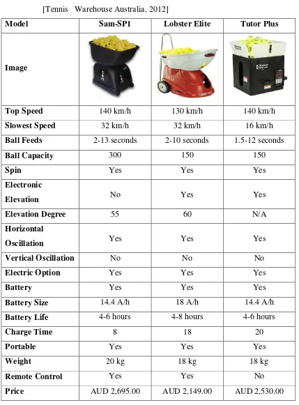
Table 3.1: Comparison between three advance tennis ball machines [Tennis Warehouse Australia, 2012]
Model Sam-SP1 Lobster Elite Tutor Plus
Image
Top Speed 140 km/h 130 km/h 140 km/h
Slowest Speed 32 km/h 32 km/h 16 km/h Ball Feeds 2-13 seconds 2-10 seconds 1.5-12 seconds
Ball Capacity 300 150 150
Spin Yes Yes Yes
Electronic
Elevation No Yes Yes
Elevation Degree 55 60 N/A
Horizontal
Oscillation Yes Yes Yes
Vertical Oscillation No No No
Electric Option Yes Yes Yes
Battery Yes Yes Yes
Battery Size 14.4 A/h 18 A/h 14.4 A/h Battery Life 4-6 hours 4-8 hours 4-6 hours
Charge Time 8 18 20
Portable Yes Yes Yes
Weight 20 kg 18 kg 18 kg
Remote Control Yes Yes No
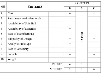
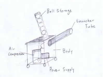
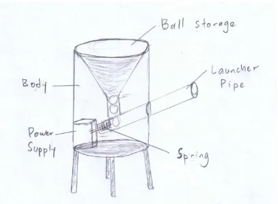
Concept evaluation and selection is the most crucial part in constructing a new product. It is used to choose the best concept design that follows company ability and fulfill customer’s requirements. For this project, there are three different concept designs generated. Each design has its own characteristics. Figure 3.1 shows Concept Design A which used rotating wheels, Figure 3.2 shows Concept Design B which used compressed air and Figure 3.3 shows Concept Design C which used spring. One of them needs to be chosen to pursue this project. So Pugh Concept Selection Method is used to select the best concept design for this project. This method compares each concept relative to a reference or datum concept by following certain procedures. Table 3.2 shows the Pugh Concept Selection Method to choose the best concept design.
Table 3.2: Pugh Concept Selection Method
NO CRITERIA
CONCEPT
B A C
1 Cost +
DA
T
UM
=
2 Suits Armature/Professionals - -
3 Availability of Spin Ball - -
4 Availability of Materials = -
5 Ease of Manufacturing + -
6 Simplicity of Design = =
7 Ability to Prototype = -
8 Ease of Assembly + -
9 Portable = =
10 Weight + +
PLUSES MINUSES
4 0 1
Figure 3.1: Concept Design A
Figure 3.3: Concept Design C
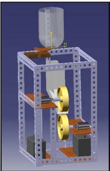
3.3 FINALIZED DESIGN
Figure 3.4: Final concept design in Catia
3.4 TECHNICAL SPECIFICATIONS
Based on the study and analysis, three main specifications must be set up in order to produce a tennis ball machine. They are height of the trajectory ball, distance travelled by the ball and trajectory speed of the ball. These specifications are very important to be followed so that they can meet the standards released by International Tennis Federation (ITF).
3.4.1 ITF Standards
levels. As custodians of the Rules of Tennis, ITF sometimes has difficult task of judging whether innovations in tennis equipment may bring about a benefit to those who play, or whether such developments constitute a threat to the nature of the game [ITF Standards, 2012].
So, in developing a new tennis ball machine, the standards and specifications published by ITF must be followed. Certain important parameters are taken from the ITF specifications to build this new tennis ball machine. The parameters are very crucial in order to produce a well-perform tennis ball machine. Examples of the parameters are stated in Table 3.3.
3.4.1.1 Tennis Ball Specifications
ITF have already published the specifications of tennis ball. The specifications include mass, size, rebound, forward deformation and return deformation. Refer Table 3.3.
3.4.1.2 Tennis Court Specifications
[image:30.595.113.530.194.463.2]ITF also published the specifications of tennis court dimension. The specifications include the dimension of base line, service line, side line and centre mark. These dimensions are shown in Figure 3.5.
Figure 3.5: Tennis court dimensions published by ITF [ITF Standards, 2012]
3.4.2 Summary of Technical Specifications
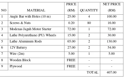
Materials that need to be bought to construct the tennis ball machine are listed. All the quantity and cost of the materials are listed in Table 3.4.
Table 3.4: Bill of materials
NO MATERIAL
PRICE
(RM) QUANTITY
NET PRICE (RM)
1 Angle Bar with Holes (10 m) 25.00 4 100.00
2 Screws & Nuts 0.20 80 16.00
3 Modenas Jaguh Motor Starter 72.00 1 72.00
4 Lathe Polyurethane (PU) Wheels 15.00 2 30.00
5 Lathe Aluminum Rods 65.00 2 130.00
6 12V Battery 27.00 2 54.00
7 Wire (2m) 5.00 1 5.00
8 Wooden Block FREE - -
9 Plywood FREE - -
TOTAL 407.00
3.6 FABRICATION PROCEDURES
1) Angle bar is measured and marked using marker and meter rule according to specified dimension as shown in Figure 3.6.
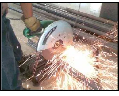
[image:31.595.241.436.593.740.2]2) The angle bar is cut using high-speed cutting machine. See Figure 3.7.
Figure 3.7: Cutting
3) The angle bars that have been cut are joined together using bolts and nuts to produce the body frame of the tennis ball machine. Refer Figure 3.8. The size of the body frame is 0.68 m height, 0.47 m width and 0.47 m length.
Figure 3.8: Joining for body frame
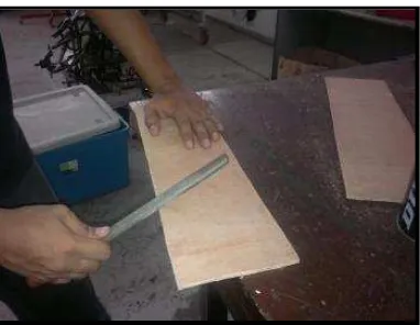
[image:32.595.186.489.448.595.2]Figure 3.9: Finishing the plywood
[image:33.595.281.394.323.472.2]5) The plywood is drilled and screwed to the machine body frame. See Figure 3.10.
Figure 3.10: Motor starter basement
6) Then a wooden block is measured and cut according to specified dimension. This wooden block is used as a holder to grip the motor starter. Figure 3.11 shows the finished wooden block.
[image:33.595.242.435.599.745.2]7) The wooden block is drilled and screwed to the basement of the machine as shown in Figure 3.12.
Figure 3.12: Motor starter holder
Figure 3.13: Assembly of aluminum rods, rollers and motor starter
[image:35.595.240.432.590.738.2]9) These assembled parts are fixed to the basement of the machine as shown in Figure 3.14 and functioned as thrower mechanism soon.
10) Then the motor starter is connected to the 12V battery using set of wires. Refer Figure 3.15.
Figure 3.15: Power supply connection
3.7 THE THROWER MECHANISM
The thrower mechanism is functioned to throw the tennis ball while the machine operates. Figure 3.16 and Figure 3.17 shows the side and front views of thrower mechanism that has been assembled together with the machine body frame.
[image:36.595.146.493.490.721.2]Figure 3.17: Front view of thrower mechanism
3.8 THE TENNIS BALL MACHINE
After assemble the thrower mechanism with the machine body frame, the whole tennis ball machine construction are finished and ready to be used. The finished machine is shown in Figure 3.18.
[image:37.595.145.493.492.724.2]3.9 FLOW CHART
[image:38.595.84.550.203.455.2]Every construction project must have its own flow chart. The flow chart is very important to show the working steps of the project. For this tennis ball machine project, the flow chart is shown in Figure 3.19.
Figure 3.19: Project flow chart
Start Choose PSM
Title Accepted
Problem Statement
Technical Specifications Design &
Fabrication Continue
Fabrication Testing &
Finalizing
Accepted Final Report
PSM 1 NO
CHAPTER 4
RESULTS
4.1 OVERVIEW
Generally, the thrower mechanism of this tennis ball machine performs very well. It can throw the tennis ball according to the technical specifications stated before. In order to ensure the thrower mechanism runs smoothly, three main factors are taken into account. The factors are throwing distance of the ball, rotating speed of the wheels and power of the motor
4.2 THROWING DISTANCE OF THE BALL
[image:39.595.125.517.629.733.2]The first factor that must be considered when constructing a thrower mechanism is the throwing distance of the ball. The distance consists of length and height travelled by the ball. This mechanism used the concept of projectile motion. Refer Figure 4.1. In order to analyze the travelling distance of the ball ejected from the rotating wheels, the theoretical calculation of projectile motion is considered.
4.2.1 Theoretical Calculation
From previous study and analysis, the ball speed range of tennis ball machine available in market is in between 20 km/h to 150 km/h. So for this project, the ball speed ejected from the launcher is assumed to be 100 km/h as the average speed. The position of the ball launcher is located 0.33 meter from the ground. So the height travelled by the ball must be combined with this value to get the total height travelled by the ball. The thrower mechanism of this tennis ball machine is designed with six elevation angles that can be adjusted. The elevation angles are 2.5°, 5.0°, 7.5°, 10.0°, 12.5° and 15°. The calculations are such below.
a) Length travelled by the ball;
Length, L = (V02 sin 2θ) / g (4.1)
[image:40.595.131.508.423.574.2] V0 = 100 km/h and g = 9.81 m/s
Table 4.1: Length travelled by ball
Elevation Angle (°) Thrown Length (m)
2.5 6.86
5.0 13.66
7.5 20.36
10.0 26.91
12.5 33.25
15.0 39.33
Height, H = [ (V02 sin2θ) / 2g ] + 0.33 (4.2)
[image:41.595.134.519.195.349.2] V0 = 100 km/h and g = 9.81 m/s
Table 4.2: Height travelled by ball
Elevation Angle (°) Thrown Height (m)
2.5 0.41
5.0 0.63
7.5 1.00
10.0 1.52
12.5 2.17
15.0 2.96
The height of tennis net from the ground is 1.07 meter. From this calculation, it shows that the ball can pass through beyond the net of the tennis court starting from 10.0° elevation angle if the tennis ball machine is placed right behind the baseline. Although the thrown height at 15.0° elevation angle quite high, it does not affect this project because there is no height limitation at the tennis court. No problem if the ball is ejected higher as long as it falls right into the opposite side.
4.2.2 Experimental Calculation
4.3 ROTATING SPEED OF THE WHEELS
In order to eject the tennis ball from the launcher, two counter rotating wheels are used. The ball from the feeder is passing through between these two wheels. Two forces of the wheels act on the ball to be push at high speed. The linear and angular speeds of the ball depend on the circumferential speeds of the wheels.
V = V1 + V2 (4.3)
2
ωr1 = V2 – V1 (4.4)
2
[image:42.595.271.417.411.628.2]Where; V1, V2 = circumferential speeds of the first and the second wheels rl = ball radius after deformation. Refer Figure 4.2
![Table 3.3: Tennis Ball Specifications published by ITF [ITF Standards, 2012]](https://thumb-ap.123doks.com/thumbv2/123dok/537462.62480/29.595.114.525.504.704/table-tennis-ball-specifications-published-itf-itf-standards.webp)
![Figure 3.5: Tennis court dimensions published by ITF [ITF Standards, 2012]](https://thumb-ap.123doks.com/thumbv2/123dok/537462.62480/30.595.113.530.194.463/figure-tennis-court-dimensions-published-itf-itf-standards.webp)