I
NFLUENCE
OF
D
ISCONTINUITIES
ON
T
HE
B
EHAVIOUR
OF
P
ARTIALLY
S
ATURATED
C
OMPACTED
C
LAY
P
ENGARUHK
ETIDAKKONTINYUANP
ERILAKUL
EMPUNG YANGD
IPADATKANP
ADAK
ONDISIJ
ENUHS
EBAGIANMiftahul Fauziah 1), Hamid R Nikraz 2)
1)
Research student, Civil Engineering Department, Curtin University of Technology e-mail: [email protected]. Lecturer, Civil Engineering and Planning Department, Islamic University of Indonesia, e-mail : [email protected]
2)
Civil Engineering Department, Curtin University of Technology, e-mail: [email protected]
ABSTRACT
The partially saturated soil behaviour is quite different from those of fully saturated soil because of the presence of matric
suction pressure. Althoughsoils are generally assumed fully saturated below the groundwater table,they may be semi
saturated near the state of fullsaturation under certain conditions. Results obtained with the strength theory of saturated soil
could not be directly applied to solve the partially saturated soil problems, in particular to the soil containing discontinuities.It has been observed that discontinuities are known to develop when such geological materials are subject to loading. In the case of strong rock, on the other hand, there has been considerable interest in the application of fracture mechanics to account for such discontinuities. Moreover, the mechanical properties of soil that usually conducted by the use of triaxial apparatus rather than biaxial device will be addressed according to the fact that field problems involving geotechnical structures are often truly or close to plane strain situation. This paper will disseminate the result of some experimental testing on the effect of discontinuities on the properties of partially saturated compacted kaolin clay specimen under triaxiall and biaxial condition. A modification of the conventional triaxial apparatus wass used in this study. A high air-entry disc (HAED) was used as the interface between the unsaturated soil and the pore water pressure measuring system. Two types of intact specimen and pre-crack specimen have been tested under biaxial as well as triaxial condition. It was concluded that the discontinuities on the specimen weaken the shear strength as well as compressive strength of specimen.
Keywords: discontinuities, partly saturated, matric suction, triaxial and biaxial
ABSTRAK
Perilaku tanah jenuh sebagian cukup berbeda dengan tanah sepenuhnya jenuh disebabkan karena adanya matric suction. Meskipun dibawah muka air tanah pada umumnya tanah diasumsikan sepenuhnya jenuh, tanah mungkin dalam kondisi jenuh sebagaian pada kondisi tertentu. Hasil hasil yang diperoleh dari teori mekanika tanah jenuh tidak bisa secara langsung diaplikasikan untuk menyelesaikan masalah masalah tanah jenuh sebagian, khususnya pada tanah yang mempunyai retakan. Observasi menunjukkan bahwa adanya retakan bisa berkembang pada saat material tanah menerima beban. Pada kasus batuan keras ,sudah mulai dipertimbangkan untuk mengaplikasikan mekanika retakan untuk memecahkan masalah ini. Terlebih lagi perilaku mekanis tanah yang biasanya diujikan dengan menggunakan alat uji triaksial pada penelitian ini akan diujikan dengan alat uji biaksial berdasarkan fakta di lapangan yang melibatkan struktur geoteknik lebih sering mendekati kondisi biaksial. Paper ini akan menampilkan hasil hasil penelitian laboratorium pada pengaruh diskontinyuitas tanah terhadap perilaku tanah jenuh sebagian pada tanah lempung kaolin spesimen pada kondisi uji triaksial dan biaksial. Modifikasi alat uji triaksial digunakan dalam studi ini. Sebuah high air-entry disc (HAED) digunakan sebagai interface antara tanah tidak jenuh dan sistem pengukuran tekanan air pori. Dua tipe spesimen intak dan spesimen yang mengandung retakan awal sudah dilakukan pengujian dibawah kondisi biaksial dan triaksial. Dari hasil pengujian dapat disimpulkan bahwa adanya diskontinyuitas pada spesimen tanah memperlemah tahanan geser dan juga kuat tekan spesimen tanah.
Kata-kata kunci: diskontinyuitas tanah ,jenuh sebagian, matric suction, triaksial and biaksial
INTRODUCTION
The behaviour of partially saturated soil is different from those of fully saturated soil because of the influence of suction. Partially saturated soils form the largest category of materials that cannot be classified by classical saturated soil mechanics con-cepts. Results obtained with the strength theory of saturated soil could not be directly applied to solve the partially saturated soil problems. Althoughsoils are generally assumed fully saturated below the groundwater table,they may be semi saturated near the state of fullsaturation under certain conditions. The situation of partial saturation maybe caused by several factors, such as varia-tion of watertable level due to natural or manmade processes.
Generally, Partially saturated soil is characterized by three phases, soil solids, water, and air. The presence of a fourth inde-pendent phase, a so called air–water interface or contractile skin was introduced by Fredlund and Morgenstern in 1977. Based on multiphase continuum mechanics, they proposed a theoretical
Many studies have been conducted on detailed aspect of such discontinuities, but these are of limited practical application in an actual situation. The existence of cracks and fissures, which are the result of mechanical, thermal and volume-change-induced stresses, such soils are non uniform and therefore not amendable to analysis by continuum mechanics. On the other hand, fracture mechanical theory may be used to advantage to replicate their behavior (Ingraffea, 1987).
Atkinson and Bransby (1982) proposed the conventional failure criteria for soils which might be partly appropriate to yield-dominant behaviour, but not this category of brittle frac-ture. In practice, there is the possibility that soil behaves more like a brittle material. The soil ruptures suddenly under compres-sive loading like soft rock, starting from the weakest crack in it. A basic premise of fracture theory is that crack like imperfections are inherent in engineering materials. These defects have the ten-dency to make stresses higher, which eventually trigger off frac-tures when a material body is subjected to a critical load or un-dergoes damage under cyclic loading. This present state of frac-ture mechanical theory has been summarized by Anderson (2004). Lo et al (2005) modeled brittle overconsolidated clay ac-cordingly and thereby provided a rational basis for the prediction of such soil behaviour.
Most laboratory experiments on soils for the purposes of evaluating constitutive behaviour and stability properties of soil are performed under axisymmetric or conventional triaxial condi-tions. However, most geotechnical field problems such as land-slide problems, failure of soils beneath shallow foundations, and failure of retaining structures are truly or close to biaxial situa-tions. Mochizuki et al (1993) reported that when soil is tested un-der plane strain conditions, it, in general, exhibits a higher com-pressive strength and lower axial strain. Behaviour of fined grain-ed sands testgrain-ed under biaxial conditions has been reportgrain-ed (Alshibli et al, 2004; Alshibli and Sture, 2000; Bizzarri, 1995; Han and Vardoulakis, 1991; Hans and Drescher, 1993; Marach et al, 1984; and Mochizuki et al, 1993). The plane strain testing of clay has only been initiated recently (Fauziah and Nikraz, 2008; Fauziah and Nikraz, 2007; Lo et al, 2000; Drescher et.al (1990)) and pu-blished data of such tests especially for brittle clay material is ve-ry limited.
This paper will present the experimental study of the beha-viour of pre-crack partially saturated clay specimens compare to the intact specimen by the use of biaxial compression apparatus as well as triaxial test set-up, although the behaviour of overcon-solidated clay (Fauziah and Nikraz, 2007) and fracture charac-teristics of brittle clay may also be determined by this test appa-ratus. Description of the apparatus, specimen preparation, testing method, procedure and data analysis will be presented in the fo-llowing discussion. Some results of the testing will be compared with the known soil behaviour and previous working.
DISCRIPTION OF THE DEVICE
A conventional triaxial apparatus was modified for the pur-pose of biaxial testing in this study. The biaxial arrangement is placed in a cell, with the height of 300 mm, 200 mm internal diameter and 30 mm wall thickness. Figure 1 shows the schema-tic diagram of the biaxial compression device.
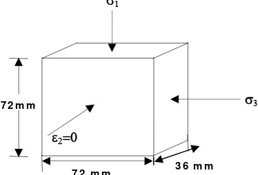
A prismatic specimen with the size of 36 mm wide, 72 mm high, and 72 mm thick, so that the aspect ratio is 2, is placed on the base pedestal where it was restrained laterally by two rigid perspex plates to restrain its out-of plane movement which make ε2=0. Therefore, only major (σ1) and minor (σ3) principal stresses
acting on the soil specimen (Figure 2).
To prevent any air from passing through the disc into the measuring system, a high air-entry disc (HAED) was used as the interface between the partly saturated soil and the pore water pre-ssure measuring system. All surfaces which are in contact with
the specimen were lubricated to avoid the likelihood of scratch-ing and reduced friction. An LVDT (Linear Vertical Displace-ment Transducer) was used to measure the axial displaceDisplace-ments of the test specimen. The global volume change of the water satura-ted soil specimen was monitored by the use of an automatic volu-me change unit which is connected to the back-pressure line. A data acquisition system consisting of an MPX 300 data logger and a set of microcomputer were used to record the displacement, loads, pressure and volume change reading of the specimen. WINHOST 2.0 package software was used to convert digital bit data from the ADU (Analogue digital Unit) to engineering units based on the calibration of the relevant measuring unit, which was done before running the plane strain test. A more detail dis-cription of this biaxial compression device can be found in pre-vious working reported by Fauziah and Nikraz (2008) and Fauziah and Nikraz (2007).
Figure 1. A schematic diagram of the plane strain device
σ
1σ
37 2 m m
ε
2=0
3 6 m m 7 2 m m
MATERIAL PREPARATION AND METHOD
The material used in this study was commercial Kaolin clay, a product of UNIMIN PTY LTD, Australia. The basic characteristics of the material are shown in Table 1.
Table 1. Basic characteristics of kaolin clay
Type of test Value
Liquid limit (ASTM D-4318) 53.5 %
Plastic limit (ASTM D-427) 30.76 %
Plasticity Index 22.74 %
Specific Gravity (ASTM D-854) 2.60
It took few weeks to complete the preparation of soil speci-men. Initially, a kaolin clay sample was slurried to a uniform consistency of 1 ½ times its liquid limit using an electrical soil mixer. This slurry was obtained by mixing 8 kg of kaolin powder with 6 kg of water using the electric mixer for about 2 hours. Before pouring the kaolin slurry to the consolidation unit, the in-ner wall of the cylinder mould was greased to ease the extrusion of the sample from the mould at the end of consolidation. A steel cylindrical mould with the height of 600 mm and 150 mm in dia-meter was used to consolidate the slurry using a hydraulic tester in over a period of one to two weeks which the maximum of 300 kPa was applied in three stages.
To apply the pressure evenly to the slurry, two circular per-spexes were placed at both ends of the slurry in the mould. The slurry was allowed to consolidate by its own weight and small pressure was applied to prevent the slurry being squeezed out between the circular perspexes and the mould. A higher vertical pressure was applied when there was no further settlement change. The soil was then extruded from the mould into lubri-cated formers when the consolidation process had completed. Fo-llowing this, the specimen and the former were wrapped in plas-tic film sheeting after sealing both their faces with liquid wax. To obtain even pore water pressure, the specimens were placed in the dehumidifier for at least 2 days until it is tested.
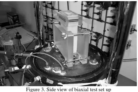
In the plane strain test set-up, the rubber membrane was firs placed over the test specimen with the aid of a sleeve stretcher. The rectangular porous plate was then placed on top of the speci-men followed by the top assembly and the HAED. The rubber membrane was next slipped over the porous plate, the top assem-bly and the HAED and secured by the use of a set of O-rings and rectangular Perspex clamp. The specimen, together with the po-rous plate and the top assembly were then placed over the pede-stal of the plane strain compression apparatus. The rubber mem-brane was next slipped over the pedestal and secured by the use of a set of O-rings and clamp set. Two rigid perspex plates were then placed and secured by the use of clamp set for biaxial test set up (Figure3). For triaxial test set up the rigid plates were un-install to specimen. The pressure cell, top assembly and laser sensor set-up were then installed.
TESTING METHOD AND PROCEDURE
Two types of intact specimen and pre-crack specimen have been tested under biaxial and triaxial condition. The pre-crack specimen were made by adding the 3 cm diagonal precrack in the center of the intack specimen to make the discontinuities in the specimen. Three specimen of IBM (intact specimen, biaxial), PCBM (Pre-crack specimen, biaxial) and ITM (intact specimen, triaxial) were tested under net normal stress of 0 and maximum matric suction of 500 kPa and three specimen of IBN (intact specimen, biaxial), PCBN (Pre-crack specimen, biaxial) and ITN
(intact specimen, triaxial) were tested under matric suction of 0 and maximum net normal stress of 800 kPa. The specimen was first saturated until the value of pore pressure coefficient (B-value) of the specimen reached the value of 0.95-0.98, followed by matric suction applied and loading compression processed.
Figure 3. Side view of biaxial test set up
A cell pressure of 600 kPa, back pressure of 590 kPa and pore pressure of 600 kPa were applied to provide an initial net normal stress (NNS) of 0 and matric suction (MS) of 10 to the to the IBM, PCBM, and ITM specimens. The volume change of the soil skeleton was monitored continuously by the laser sensors. The change in volume of water in the specimen was also moni-tored continuously by the volume change gauge which was con-nected to the back-pressure line. Once the changes in the soil and water volumes had ceased, the test specimen was presumed to ha-ve fully consolidated under a matric suction of 10 kPa. The ma-tric suction was next increased to 20 kPa by reducing the back pressure to 580 kPa. The corresponding changes in the soil skele-ton and water volumes were monitored continuously until they had ceased, at which stage the corresponding void ratio and the water content of the test specimen were computed from the cu-mulative changes in soil skeleton and water volumes. The entire procedure, that is from increasing the matric suction to the desired value up to flushing out the air bubbles, was repeated for matric suctions of 50, 100, 200, 300, and 500 kPa respectively, which were applied by reducing the back pressure accordingly.
Another test apparatus were set up for IBN, PCBN, and ITN specimens similarly as before, except that the head was replaced with a porous disc. A cell pressure of 110 kPa, back-pressure of 100 kPa and pore-air back-pressure of 100 kPa were then applied to the specimen to provide an initial net normal stress of 10 kPa and matric suction of 0. The changes in soil skeleton and water volumes were then monitored continuously and when these changes had ceased, the total changes in soil and water volumes were noted. The net normal stress was first increased to 20 kPa by increasing the cell pressure to 120 kPa. Thereafter, the entire above procedure, starting from applying the net normal stress up to when the changes in soil and water volumes ceased, was re-peated for net normal stresses of 50, 100, 200, 300, 500 and 800 kPa.
The specimen was then compressed by elevating the base of the confining pressure cell at a constant velocity of 0.08 mm/m with the drainage line closed at at net normal stress of 0 and ma-tric suction of 500 kPa for IBM, PCBM, and ITM specimen and at matric suction of 0 and net normal stress of 800 kPa for IBN, PCBN, and ITN specimen.This loading rate was deduced based on the permeability of adopted kaolin clay suggested by Bishop and Henkel (1962).
un-saturated clay, the pore pressure parameter would be required in order to the determined the pore pressure increments and the ma-tric suction. The pore pressure parameters were deduced from the volumetric deformation coefficient, which was obtained by labo-ratory testing. This procedure was proposed by Fredlund and Rahardjo (1993), although adapted to biaxial conditions.
TEST RESULT AND DISCUSSION
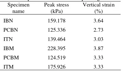
The typical result given by specimens tested under biaxial condition of IBM, IBN, PCBM, and PCBN as well as specimen observed under triaxial test set up of ITM and ITM will be dis-cussed in the following discourse. The strain softening response of the intact and pre-crack specimen tested under biaxial test set up are depicted in Figure 4 and stress-strain curves of the intact specimen tested under biaxial and triaxial condition presented in Figure 5. The peak stress and the corresponding strain of the spe-cimen is summarised in Table 2.
Table 2. The peak stress vs the corresponding axial strain Specimen
name
Peak stress (kPa)
Vertical strain (%)
IBN 159.178 3.64
PCBN 125.336 2.73
ITN 139.464 3.03
IBM 228.395 3.87
PCBM 124.519 3.33
ITM 175.926 3.33
In general, the shear stress or deviatoric stress curves in-crease monotonically with the increasing vertical strain until they reach peak stresses followed by strain softening behaviour. Ac-cording to Lo et all (2005) this is the typical phenomenon of spe-cimen of brittle, hard partly saturated soil spespe-cimen and exhibit elastic only.
As can be seen in Figure 4, the shear stress of the intact specimen of IBM and IBN were higher along the vertical strain than that the specimen containing discontinuities or pre-crack of PCBM and PCBM specimen. The highest failure stress of 228.395 kPa was reached by the intact specimen of IBM, and the lowest failure stress of 124.519 kPa was derived by the pre-crack specimen of PCBM. The presence of a fissure or discontinuity makes the soil weaker as the effective area offering resistance to shear is reduced. The shear strength along a surface of disconti-nuity is thereby less than that of the intact material. It is also shown from the graph that the pronounced peak shear strengths were occurred to the pre-crack specimen than the intact speci-men. Similar observation of pre-crack overconsolidated clay had been reported elsewhere (Lo et al, 2000).
The shear stress versus axial strain curves of intact speci-men under biaxial and triaxial testing were presented in Figure 5. The graph shows that under the same matric suction and net nor-mal stres the biaxial specimen of IBM had higher shear stress a-long the strain than that the specimen of ITM which was tested at triaxial test set up, as well as the IBN specimen compared to the ITN specimen. The triaxial specimen also reached earlier peak strength at 3.03 % and 3.33 % axial strain for ITM and ITN respectively than that the biaxial specimen of IBM and ITM at 3.87 % and 3.64 % respectively. This result seem to be consistent with the founding of Mochizuki et al (1993).
0 25 50 75 100 125 150 175 200 225 250
0 1 2 3 4 5 6 7
axial strain (%)
D
ev
iat
o
ri
c st
re
ss (
k
P
a)
IBN (Intact, biaxial) PCBN (Pre-crack, biaxial) IBM (Intact, biaxial) PCBM (Pre-crack, biaxial)
Figure 4. Stress strain behaviour of intact and pre-crack specimen under biaxial testing
0 25 50 75 100 125 150 175 200 225 250
0 1 2 3 4 5 6 7
axial strain (%)
D
e
v
iatoric stress (kP
a
)
IBN (Intact, biaxial) ITN (Intact triaxial) IBM (Intact, biaxial) ITM (Intact triaxial)
Figure 5. Stress strain of intact specimen under biaxial and triaxial testing
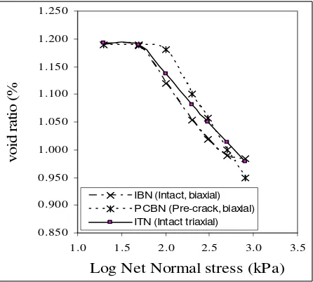
Figure 6 and Figure 7 present the constitutive surface of void ratio versus log net normal stress and log matric suction of the specimen. The slope of the intersection curves are the volume change index Cm and water content index Dm respectively for the
case that net normal stress set to zero, whereas the slope of the intersection curves are the volume change index Ct and water
content index Dt when the matric suction set to zero. Ct is the
slope of the consolidation curve and is equal to the compressive index of a saturated soil, while Cm is the slope of the shrinkage
1.170 1.175 1.180 1.185 1.190 1.195
1.0 1.5 2.0 2.5 3.0 3.5
Log Matric suction (kPa)
V
o
id
r
a
tio
(%
)
IBM (Intact, biaxial) PCBM (Pre-crack, biaxial) ITM (Intact triaxial)
Figure 6. Void ratio versus matric suction of IBM, PCBM and ITM specimens
0.850 0.900 0.950 1.000 1.050 1.100 1.150 1.200 1.250
1.0 1.5 2.0 2.5 3.0 3.5
Log Net Normal stress (kPa)
v
o
id
ratio (
%)
IBN (Intact, biaxial) PCBN (Pre-crack, biaxial) ITN (Intact triaxial)
Figure 7. Void ratio versus matric suction of IBN, PCBN and ITN specimens
The value of the volume change index of the IBM, PCBM and ITM specimens were calculated as 0.011, 0.016, and 0.017 respectively. The value of the Ct of the IBN, PCBN and ITN specimens are 0.219, 0.257 and 0.232 respectively. The higher slope of ITN and ITM curves than that of IBN and ITM curve in-dicated that the specimen tested at biaxial condition had higher compressive strength than that of specimen tested under triaxial test set up. This is in well agreement with the observation repor-ted by Mochizuki et al (1993). It is also clearly shown that the specimens containing precrack of PCBM and PCBN had higher compressive index than that the intact specimens of IBM and ITN.
The change in water content of the specimen in relation with matric suction (MS) and net normal stress (NNS) depicted in Figure 8 and Figure 9. The constitutive surface of water con-tent is defined by the compressive index Dm and Dt correspond-ing to the matric suction and net normal stress respectively. The value of compressive index obtained by determining the gradient of the linear portion of the curve of the water content against the log of matric suction for Dm and the log of net normal stress for Dt.
As can be seen from the graph that the curve went down with the increasing of either matric suction or net normal stress for all the specimens. The curve also indicated that the higher gradient value of 0.071 and 0.068 were reached by pre-crack specimens of PCBM and PCBN respectively than that the gra-dient value of intact specimens of IBM and IBN which were 0.55 and 0.056 respectively (Figure 8). Similar to the curve of the volume change result on Figure 6 and Figure 7, and consistent with the stress-strain behaviour of the specimens shown on Fi-gure 4 and FiFi-gure 5, the existence of the crack or discontinuities on the specimen not only weaken its shear strength as well as its compressive strenght but they also quicken the failure of the specimen.
0.12 0.14 0.16 0.18 0.20 0.22 0.24 0.26
1.0 1.5 2.0 2.5 3.0 3.5
Log (MS, NNS) kPa
W
at
er
c
ont
en
t
(%
)
IBN (Intact, biaxial) PCBN (Pre-crack, biaxial) IBM (Intact, biaxial) PCBM (Pre-crack, biaxial)
Figure 8. Water content change of intact and pre-crack specimen under biaxial testing
0.13 0.15 0.17 0.19 0.21 0.23 0.25 0.27
1.0 1.5 2.0 2.5 3.0 3.5
Log (MS, NNS) kPa
W
a
ter content (%
)
IB N (Intact, biaxial) ITN (Intact triaxial) IB M (Intact, biaxial) ITM (Intact triaxial)
Figure 9. Water content change of intact specimen under biaxial and triaxial testing
CONCLUSION
The following conclusions might be drawn from this experimental study.
1. The typical of brittle hard clay and exhibit elastic only be-haviour were shown by all the specimen tested.
2. Shear strength of the intact specimen were higher along a-xial strain than that the intact specimen. It is also shown that the pronounced and lower value of peak shear strength we-re occurwe-red to the pwe-recrack specimen than the intact speci-men.
3. The weaken compressive strength of the specimen contain-ing discontinuities were indicated by their higher volume change index than the intact specimen’s.
4. Under the same matric suction and net normal stress the spe-cimen tested under plane strain condition exhibits a higher compressive strength than that the specimen tested under triaxial test setup.
ACKNOWLEDGMENT
The authors generously give acknowledgment to Professor Kwang Wei Lo from National University of Singapore and Dr Min Min Zhao for their valuable advice and support.
REFERENCES
Alshibli, K.A. and Sture, S., 2000, Shear bands formation in plane strain experiments of sand, Journal of Geotechnical
and Geoenvironmental Engineering, v 126, n.6, June, ASCE,
Paper no.21167, ASCE, USA.
Alshibli, K.A., Godbold, D. L.,and Hoffman, K., 2004, The Louisiana Plane strain apparatus for soil testing,
Geotechni-cal Testing Journal, v 27, n 4, July, p 337-346, ASTM, US.
Anderson, T.L., 2004, Fracture mechanics: fundamental and
aplications, 3rd ed., CRC Press, London, UK.
Atkinson, J.H. and Bransby, P.L., 1982, The mechanics of soils :
an introduction to critical state soil mechanics.
McGraw-Hill, New York, US.
Atkinson, J.H. and Richardson,D., 1987, The effect of local drai-nage in shear in shear zones on the undrained strength of o-verconsolidated clay. Geotechnique, 37 (3), 393-403, Thomas telford, UK.
Bizzarri, A., Allersma, H. G. B., Koehorst, B. A. N., 1995, Preli-minary tests on soft clay with a biaxial apparatus, Procee-dings of the 1995 International Symposium on Compression
and Consolidation of Clayey Soils. Part 1 (of 2), May 10-12
1995, Hiroshima, Japan.
Fauziah, M. and Nikraz, H, 2007, Biaxial testing of overcon-solidated clay, Proceeding of The1st International Conference
of European Asian Civil Engineering Forum, Universitas
Pelita Harapan, 27-28 September 2007, Jakarta, Indonesia.
Fauziah, M. and Nikraz, H., 2007, Stress-strain behaviour of overconsolidated clay under plane strain condition,
Proceed-ing of The 10th Australia New Zealand conference on
geome-chanics, Australian Geomechanics Society, 21-25 October
2007, Brisbane, Australia.
Fauziah, M. and Nikraz, H, 2008, The behaviour of unsaturated compacted clay under plane strain condition, Proceeding of
The3rd International conference on Geo-Environment and
Landscape Evolution, Wessex Institute of Technology, 16-18
Jun 2008, The New Forest, UK.
Fauziah, M. and Nikraz, H., 2008, Volume change behaviour of unsaturated compacted clay under plane strain condition strain condition, The Australian Earth Science Convention, Geological Society of Australia, 20-25 July 2008, Perth, Australia.
Fredlund, DG and Rahardjo, H (1993). “ Soil mechanics for
unsaturated soil, John Willey & Sons, Inc, US.
Grammatikopoulou, A, 2004, Development, Implementation and Application of Kinematic Hardening Models for Overconso-lidated Clays, Phd Thesis, Imperial College, London. Han, C. and Drescher, A., 1993, Shear bands in biaxial tests on
dry coarse sand. Soils and Foundations, Japanese Society of
Soil Mechanics and Foundation Engineering, Vol.33, No.1,
pp.118-132, JSSMFE, Japan.
Han, C and Vardoulakis, I.G., 1991, Plane strain compression experiments on water-saturated fine-grained sand,
Geotech-nique, Vol. 41, No.1, pp.49-78, Thomas telford, UK.
Head, K.H., 1986, Manual of Soil Laboratory Testing. Vol 3, Pentech Press, London, UK.
Ingraffea,AR (1987). “Theory of crack initiation and propagation in rock”, In Fracture Mechanics of Rocks, ed by B.K. Atkinson, pp.71-110,: Academic Press, London, UK. Lo, K.W., Nikraz, R.H.,Tamiselvan, T. and Zhao,M.M., 2005,
An elastoplastic shear fracture model for soil and soft rock,
Procceding of the 11th International Conference on
Fracture, ICF XI, ASTM, 20-25 March 2005, Turin, Italy.
www.icf11.com/proceeding/TOPIC/topic.htm
Lo, K.W., Mita, K.A., and Tamiselvan, T., 2000, Plane Strain Testing of Overconsolidated Clay, Research Report, Depart-ment of Civil Engineering, National University of Singapore. Mochizuki, A., Min, C. and Takahashi, S.A., 1993, A method
for plane strain testing of sand. Journal of Japanese
Geotech-nical Society, No.475, pp.99-107, JGT, Japan.
Marach, N.D., Duncan, J.m., Chan, C.K. and Seed, H.B., 1981,
Plane strain testing of sand, laboratory shear strength of soil.
ASTM STP 740, pp.294-302.
Viggiani, G., Finno, R.J. and Harris, W.W., 1994, Experimental Observations of strain localisation in plane strain
compres-sion of a stiff clay. In Localisation and Bifurcation Theory for
Soils and Rocks, Chambon et.al., Eds., pp.189-198, Balkema, R