ATMEGA16 IMPLEMENTATION AS
INDICATORS OF MAXIMUM SPEED
1
Anna Nur Nazilah Chamim,
2
Didik Ahmadi,
3
Iswanto
Motorcycle accidents caused by sudden deceleration or exceed maximum safe speed of vehicles are still common. There is no tool that can provide alerts when the speed has exceeded the safe speed limit for vehicles allowed. Hence, the study aims to design and manufacture implementation of ATmega16 as an indicator of the maximum speed. Output data is obtained in the form of increasing speed. Maximum speed indicator system consists of atmega 16 as the main processing unit, sensor optocoupler, 4x4 keypad, buzzer and LCD LM162. It includes the output of the transducer which is processed by a microcontroller keypad which is then forwarded to the buzzer and LCD LMB162. Testing is conducted by direct tests on the vehicle running, and the obtained results show the maximum speed indicator device made to work properly and in accordance with the specifications of the predetermined design, so that it can give a warning when the safe speed is being and has been exceeded.
Keywords: Microcontroller, Indicators, Maximum speed, Motorcycles, Vehicle accident
INTRODUCTION
Each vehicle has different characteristics particularly two-wheeled vehicles. At first the characteristics of two-two-wheeled vehicles with the same type of products are the same. But having reached the users, the characteristics are changing because they adapt to the characteristics of the users. The characteristics of the vehicle affects the safe speed that can be achieved. Safe speed is the speed that is considered safe meaning that the vehicle does not slip or is stable when the rider conducts sudden deceleration. Safe speed of a vehicle can only be determined by those who are riding it, in other words safe speed is a speed limit that is considered to be controlled by the rider while riding. Motorcycle accident is frequently caused by a rider who did sudden deceleration, and because it exceeds the maximum safe speed for the vehicle. A tool that can be used as speed indicators and may give a warning when the speed has exceeded the safe speed limit allowed for vehicles is needed to reduce and avoid accidents caused by speeds exceeding the safe speed limit. Some previous researchers have conducted researches on measuring speed included Rajab et al. [1] using piezoelectric to measure the speed of a vehicle. Some other researchers such as Zhang et al. [2] used sensor less speed to measure BLDC motor speed.
The other researchers applied microcontroller and FPGA to measure the speed of the motor. Millan-Almaraz et al. [3] used FPGA control to measure the speed of the motor with wavelet algorithm. In addition to using FPGA, the other researchers such as Nadh & Praba [4] used PIC microcontroller to remotely monitor the speed of an induction motor while using zig bee and SMS to transmit speed data. PIC microcontroller was also used by Isik et al. [5] to monitor the motor speed of permanent magnet DC (PMDC). The motor speed data were monitored and plotted by using fuzzy algorithms.
Fuzzy algorithm is an artificial intelligence algorithm used to control a system such as quadrotor [6],[7] and to create path planning as practiced by Iswanto et al. [8],[9] applying fuzzy path planning on a quadrotor. In artificial intelligence system, the algorithm was also used by Tunggal et al.[10] to detect the heart rate.
This paper presents fuzzy algorithm applied to the microcontroller used to monitor the speed of a motor cycle. With the algorithm, the microcontroller can calculate the speed of the motorcycle and give a warning if the speed used exceeding the maximum speed limit
RESEARCH METHOD
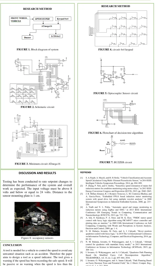
FIGURE 1. Block diagram of system
FIGURE 2. Schematic circuit
FIGURE 3. Minimum circuit ATmega16
DISCUSSION AND RESULTS
Overall Equipment Testing Phase.
In this stage the first step to do that is to know the length and the ratio of the circumference of a full cycle of the front wheels noted in interrupt ATmega16 microcontroller. The data obtained is shown in table 1.
TABLE 1:THE COMPARISON OF THE WHEELS.
NO front wheel speedometer Wheels Interrupt 1 1 2.6 10 The data from table 1 then inputted into the program with the following specifications:
Interruptions obtained are used to add value to data count.
Data count is reset every one second.
If one interrupt obtained by the microcontroller ATmega16 represents the distance of 0.17 m, by applying the formula in the form of speed distance per time, the reached speed value is gained. The speed that still has units of meters per second then converted into kilometers per hour using the following formula:
1 m / sec = 1 * (1/1000: 3600) km / h = 1 * 3.6 km / h
Interpreted into the following program: kecps = (float) data_count * 0.17 *3.6;
Where the variable representing the distance and variable 0:17 3.6 is the conversion factor obtained.
DISCUSSION AND RESULTS
Testing has been conducted to rate setpoint changes to
determine the performance of the system and overall
work as expected. The input voltage must be above 8
volts and below or equal to 24 volts. Distance to the
sensor mounting plate is 1 cm.
Figure 8: occupancy sensors
REFRENSI
[1] S. A. Rajab, A. Mayeli, and H. H. Refai, “Vehicle Classification and Accurate Speed Calculation Using Multi- Element Piezoelectric Sensor,” in 2014 IEEE Intelligent Vehicles Symposium Proceedings, 2014, pp. 894–899. [2] P. Zhang, P. Neti, and S. Grubic, “Sensorless speed estimation of mains-fed
induction motors for condition monitoring using motor relays,” in 2015 IEEE Energy Conversion Congress and Exposition (ECCE), 2015, pp. 2840–2845. [3] J. R. Millan-Almaraz, R. J. Romero-Troncoso, L. M. Contreras-Medina, and A. Garcia-Perez, “Embedded FPGA based induction motor monitoring system with speed drive fed using multiple wavelet analysis,” in 2008 International Symposium on Industrial Embedded Systems, 2008, pp. 215– 220.
[4] A. Nadh and N. L. Praba, “Automatic speed and torque monitoring in induction motors using ZigBee and SMS,” in 2013 IEEE International Conference ON Emerging Trends in Computing, Communication and Nanotechnology (ICECCN), 2013, pp. 733–738.
[5] A. Isik, O. Karakaya, P. A. Oner, and M. K. Eker, “PMDC motor speed control with fuzzy logic algorithm using PIC16F877 micro controller and plotting data on monitor,” in 2009 Fifth International Conference on Soft Computing, Computing with Words and Perceptions in System Analysis, Decision and Control, 2009, pp. 1–4.
[6] N. M. Raharja, Iswanto, M. Faris, and A. I. Cahyadi, “Hover position quadrotor control with fuzzy logic,” in 2014 The 1st International Conference on Information Technology, Computer, and Electrical Engineering, 2014, pp. 89–92.
[7] N. M. Raharja, Iswanto, O. Wahyunggoro, and A. I. Cahyadi, “Altitude control for quadrotor with mamdani fuzzy model,” in 2015 International Conference on Science in Information Technology (ICSITech), 2015, pp. 309–314.
[8] I. Iswanto, O. Wahyunggoro, and A. I. Cahyadi, “Quadrotor Path Planning Based On Modified Fuzzy Cell Decomposition Algorithm,” TELKOMNIKA, vol. 14, no. 2, pp. 655–664, 2016.
[9] I. Iswanto, O. Wahyunggoro, and A. Imam Cahyadi, “Path Planning Based on Fuzzy Decision Trees and Potential Field,” Int. J. Electr. Comput. Eng., vol. 6, no. 1, p. 212, 2016.
[10] T. P. Tunggal, A. Latif, and Iswanto, “Low-cost portable heart rate monitoring based on photoplethysmography and decision tree,” in ADVANCES OF SCIENCE AND TECHNOLOGY FOR SOCIETY: Proceedings of the 1st International Conference on Science and Technology 2015 (ICST-2015), 2016, p. 090004.
RESEARCH METHOD
FIGURE 4. circuit 4x4 keypad
FIGURE 5. Optocoupler Sensor circuit
FIGURE 6. Flowchart of decision tree algorithm
FIGURE 7. BUZZER circuit
1,2,3
Department of Electrical Engineering, Universitas Muhammadiyah Yogyakarta
.CONCLUSION