CONCEPTUAL DEVELOPMENT OF GEAR BRAKING SYSTEM
MOHD SHUKOR HADRAN
This thesis is submitted to the Faculty of Mechanical Engineering, in partial fulfillment of the partial requirement for Bachelor of Mechanical Engineering (Design & Innovation)
FACULTYOF MECHANICAL ENGINEERING UNIVERSITI TEKNIKAL MALAYSIA MELAKA
DECLARATION
“I hereby declared that I have read through this thesis and found that it has comply the partial fulfillment for awarding the degree of Bachelor Mechanical Engineering
(Design & Innovation)”
Signature : ………
i
DECLARATION
“I hereby declared that this thesis is my original work except for questions and citations, which have been duly acknowledgment”
Signature : ………
Supervisor’s name : Mohd Shukor Hadran
DEDICATION
To my beloved family’s My love ones
All friends Lectures of FKM
iii
ACKNOWLEDGEMENTS
Alhamdulillah praise to the gratefulness of Allah S.W.T in order to completion of my Projek Sarjana Muda I (PSM I) project. A special thank to the Mechanical Engineering Faculty of Universiti Teknikal Malaysia Melaka (UTeM) for approving my own project title and giving me an opportunity to do research on Conceptual Development of Gear Brake System (GBS).
A special note of thanks to Mr. Mochamad Safarudin for getting me started my PSM project under his supervision and for his assistance, guidance and helpful discussions throughout this semester which have involved significant efforts over development of system concept.
I owe a debt of thanks to Mr. Mohd Suffian Abdul Mues for his past work on Magnetic Brake Design and Simulation that provided a base-line comparison for the concept developed here.
I also would like to extend my heartfelt gratitude and appreciation to all staff from the Mechanical Engineering Faculty of UTeM especially Miss Siti Norbahyah whose time, concern and efforts were given.
ABSTRACTS
v
ABSTRAK
CONTENT
CHAPTER TITLE PAGE
DECLARATION i
DEDICATION ii
ACKNOWLEDGEMENT iii
ABSTRACT iv
ABSTRAK v
CONTENT vi
LIST OF TABLE vii
LIST OF FIGURE viii
LIST OF SYMBOLS ix
LIST OF APPENDIX x
CHAPTER I INTRODUCTION
1.0 Introduction 1
1.1 Motivation for Development of System 2
1.2 Project Problem Statement 3
1.3 Objective 3
1.4 Scope 4
1.5 Planning and Execution 5
CHAPTER 2 LITERATURE REVIEW
2.0 Introduction 6
2.1 Braking Techniques 6
vii
2.2.1 Friction Brakes 8
2.2.2 Electric Brakes 8
2.3 Braking Systems 9
2.3.1 Air Brake System 9
3.3.2 Hydraulic Brake System 9
3.3.3 Vacuum Brake System 10
2.4 Gears 10
2.4.1 Terminology for Spur Gears 11
2.5 Planetary Gear Trains 12
2.6 Manual Transmission System 14
2.6.1 Introduction to Manual Transmission 14 2.6.2 Transmission Components 16
2.6.2.1 Shafts 16
2.6.2.2 Dog Clutch 17 2.6.2.3 Shift Forks 18 2.6.2.4 Transmission Gear 19
CHAPTER 3 METHODOLOGY
3.0 Introduction 20
3.1 Concept Development 20
3.2 The Operation of the System 22
3.3 Gear Brake System (GBS) 23
3.3.1 Mechanical Components 25
3.3.1.1 Planatary/Epicyclic Gear 25
3.3.1.2 Housing 27
3.3.1.3 Sliding Clutch 28
3.3.1.4 Thrust Ring 30
3.3.1.5 One-Way Clutch 30
3.3.2 Hydraulic Flows 31
3.4 Energy Source 33
CHAPTER 4 RESULT
4.0 Introduction 34
4.1 Development Process 34
4.1.1 The Concept 34
4.1.2 Key Features 35
4.2 Technical Challenges 36
4.2.1 Transmission Housing 36
4.2.2 Planet gear Carrier Speed 37
4.2.3 Gear Trains Efficiency 37
4.2.4 Shifting Into Reverse 37
4.3 Details Drawing 37
CHAPTER 5 DISCUSSION
5.1 Calculation and Analysis 41
5.1.1 Tooth profile 41
5.1.2 Power Consumed 45
5.1.3 Fluid Volume Required 46
CHAPTER 6 CONCLUSION 48
REFERENCE 49
ix
LIST OF TABLE
NO TITLE PAGE
1 Table 1: Gant-chart of project planning for PSM1 5 2 Table 2: Gant-chart of project planning for PSM1 5
3 Table 3: The fastest method of braking 7
4 Table 4: Ratios and combinations of planetary gear. 26
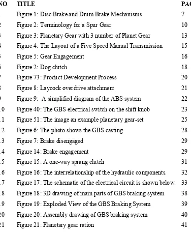
LIST OF FIGURE
NO TITLE PAGE
1 Figure 1: Disc Brake and Drum Brake Mechanisms 7
2 Figure 2: Terminology for a Spur Gear 10
3 Figure 3: Planetary Gear with 3 number of Planet Gear 13 4 Figure 4: The Layout of a Five Speed Manual Transmission 15
5 Figure 5: Gear Engagement 16
6 Figure 2: Dog clutch 18
7 Figure 73: Product Development Process 20
8 Figure 8: Laycock overdrive attachment 21
9 Figure 9: A simplified diagram of the ABS system 22 10 Figure 40: The GBS electrical switch on the shift knob 23 11 Figure 51: The image an example planetary gear-set 25 12 Figure 6: The photo shows the GBS casting 28
13 Figure 7: Brake disengaged 29
14 Figure 14: Brake engagement 29
15 Figure 15: A one-way sprang clutch 31
16 Figure 16: The interrelationship of the hydraulic components. 32 17 Figure 17: The schematic of the electrical circuit is shown below. 33 18 Figure 18: 3D drawing of main parts of GBS braking system 38 19 Figure 19: Exploded View of the GBS Braking System 39 20 Figure 20: Assembly drawing of GBS braking system 40
[image:12.612.117.493.153.609.2]xi
LIST OF SYMBOL
Vr Reference velocity Ωw Wheel spin velocity Rtire Tire rolling radius π Pie = 3.142 mm Millimeter
RPM Revolution per minutes OD Overdrive
HP Horsepower
ABS Antilock braking system GBS Gear braking system r Ring gear/annulus
P Planet gear
s Sun gear
N Number of teeth
Pd Diametral pitch Φ Pressure angle D Pitch diameters p Circular pitch a Addendum b Dedendum C Clearance
xiii
LIST OF APPENDIX
NO TITLE PAGE
1 APPENDIX 1 UK Highway Code guidelines 53
2 APPENDIX II HVE ABS Tire Slip Algorithm 54
3 APPENDIX III 2006 GTO Specifications 55
4 APPENDIX IV TREMEC T-56 Product Specifications 56
5 APPENDIX V Annulus Drawing 57
6 APPENDIX VI Bearing Annulus Drawing 7 APPENDIX VII Bearing Clutch Drawing 8 APPENDIX VIII Circlip Drawing
9 APPENDIX IX Circlip Sliding Clutch Drawing 10 APPENDIX X Circlip Thrust Plate Drawing 11 APPENDIX XI Front Casing Drawing 12 APPENDIX XII Oil Thrower Drawing 13 APPENDIX XIII Planet Gear Drawing
14 APPENDIX XIV Planet Gear Carrier Drawing 15 APPENDIX XV Planet Gear Shaft Drawing 16 APPENDIX XVI Rear Casing Drawing 17 APPENDIX XVII Sliding Clutch Drawing 18 APPENDIX XVIII Sun Gear Drawing
19 APPENDIX XIX Thrust Bearing Housing Drawing 20 APPENDIX XX Thrust Plate Drawing
21 APPENDIX XXI Thrust Washer Drawing
CHAPTER I
INTRODUCTION
1.0 Introduction
In section I we explain about the ideas behind the project of development a Gear Brake System (GBS) where the need of emergency situations and the weakness of the Antilock Braking System (ABS) itself are discuss. The threshold braking and locked wheels braking methods reveal that ABS is not the fastest ways of stopping the vehicle and its tend to behave unexpectedly in certain roads conditions.
In section II we represent a short-course discussion regarding the system that being involve and give a brief explanation on the ways of it operates as reference learning for the GBS system. An introduction into brake types and gear design is being discussed as it provides a basic idea for the system operation. As the means of power transmit from the engine to the wheels, a manual gear transmission is essentially discussed here.
In section III we provide a product development and analysis for simulation model of the system that was motivated and design based on the J type overdrive (OD) unit manufactured by Laycock-de-Normanville. To suit the purpose of GBS as a braking system, we have changes the planetary gear sub-system of OD so that it provides a low speed and high torque reverse rotational from the engine to the wheels.
2
After detailing design of the GBS braking system, calculation is done to find adequate tooth profile of planetary gear to meshing, amount of power consumed by the system and volume of lubricant that are needed for the hydraulic pump to supply enough pressure for the operations of the system. This is presented in sections V
While this study provided basics concept for development of mathematical model for simulation and validation of the operating principles, we do some recommendation regarding further studies and works for more in-depth research on performance and behaviors of gear braking system in sections VI
1.1 Motivation for development of gear braking system
ABS is designed to stop vehicles as safely and quickly as possible. Safety is achieved by maintaining lateral stability and hence steering effectiveness and trying to reduce braking distances over the case where the brakes are controlled by the driver. Improving the stopping distance of a vehicle helps to reduce collisions, casualties and damage to vehicles and goods.
The basic ABS algorithm continuously releases the brake pressure only to later reapply the full brake pressure, once wheel lock-up has been prevented. Essentially, as the wheel slip increases past a critical point where it is possible that lateral stability and hence our ability to steer the vehicle could be lost, the controller releases the brakes. Then, once wheel slip has decreased to a point where lateral stability is increased and braking effectiveness is decreased, the brakes are reapplied. In this way the ABS cycles the brakes to try to achieve an optimum tradeoff between braking effectiveness and lateral stability.
ice make the ABS control problem challenging and thus increases the stopping distance.
In this paper, we consider brake system for an “emergency stop,” and hence for our study the brakes are in an ABS mode. We seek to develop a system that will ensure that the braking torque commanded by the driver is achieved by the brake system. Clearly, solving the emergency braking problem is of significant importance since there is a direct correlation between safety and the reliability of the brakes in providing the commanded stopping force. Moreover, tire-slip algorithms of ABS controllers could also enhance braking effectiveness while in ABS mode.
Prior research on the braking system considered here has shown that one of the primary difficulties with the brake system lies in compensating for the effects of changes in the “transmission system”, that occur due to shifting an manual or automatic transmission into reverse while the car is moving forward will not engage reverse gear.
1.2 Project Problem Statement
ABS was designed to help the driver maintain some steering ability and avoid skidding while braking rather than to slow down and stop the vehicle. This substantially improves driving stability by ensures that the vehicle can still be steered and moved out of the way of unexpected obstacles. This is however in contras increase vehicle stopping distance as well as stopping time especially over loose gravel.
1.3 Objective
4
relevant undertake to the project. It is to produce students that are capable of doing an assessment and evaluation on ones. It is also to train students so that they are able to operate works with minimum valuations and more independent in conducting and producing an academic project and further capable in delivering project work revenue through seminar and written report. As an addition, this project also is for planting and enhances student interest so that are interested to dabble in the field of research. The objectives of this project are as below:
Develop a mechanism for braking system by means of gearing. Design a concept of gear braking system
1.4 Scope
Develop a concept of brake system that using gears as its mechanism Design the details of the system and system 3D drawing
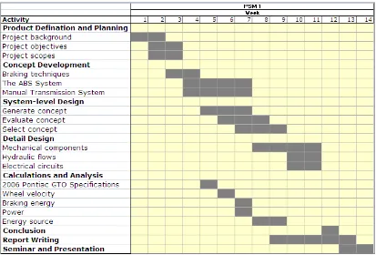
1.5 Planning and Execution (GANT-CHART)
[image:20.595.113.526.151.431.2]The planning schedules of the project are as follow:
Table 1: Gant-chart of project planning for PSM1
[image:20.595.112.521.473.754.2]6
CHAPTER II
LITERATURE REVIEW
2.0 Introduction
The literature is information and past studies on the braking techniques, brake types, braking systems, gear technologies, manuals transmission system and planetary gear train. The literature review for this project is found threw sources from thesis, reports, journal, articles, manuals, books and web pages.
2.1 Braking Techniques
There are several braking techniques which will be discussed here, which will consider cars with and without ABS, as many of the techniques listed here will not be relevant in car equipped with ABS or anything that mentions wheels locking. A good braking technique is a compromise between the two following factors:
a) When the limits of grip have been reached that makes wheel locked, the tire no longer retains the ability to accept steering inputs thus lose control. b) The point of maximum deceleration is just before the point of wheel lock
Rank Braking method
First Threshold braking
Second Locked wheels
Forth Cadence braking
[image:22.595.113.521.70.112.2]Fifth Parachute
Table 3: The fastest method of braking
Table above show the fastest method of slowing down for a vehicle, noted that the ABS is placed third after threshold braking and locked wheels methods. This has elements of truth; threshold braking and locked wheels methods can slow a vehicle more quickly that a car fitted with ABS if done correctly in the right conditions. But in practical terms the benefits of ABS massively outweigh the slightly longer braking distances and ABS is an absolute must as it will allow vehicle to steer out of the way of unexpected hazards thus significantly improves safety and control for drivers in most on-road situations.
2.2 Brake Types
[image:22.595.111.524.520.745.2]Brake is a device used to slow down later stop the motion of a mechanism or vehicle while a type of brakes is the apparatuses it used. Drum brake and disk brake mechanism for example that slows and stops a car is by fiction, that is pressing brake shoes or disk against a drum or wheel axel.
8
2.2.1 Friction Brakes
Friction brakes is the most common kind of brake type, operate on the principle that friction can be used to convert the mechanical energy of a moving object into heat energy, which is being absorbed by the brake. The essential components of a friction brake are a rotating part, such as a wheel, axle, disk, or brake drum, and a stationary part that is pressed against the rotating part to slow down and stop it. The stationary part usually has a lining called a brake lining, which can generate a great amount of friction yet, give long wear.
The principal types of friction brake are the block brake, the band brake, the internal-shoe brake, and the disk brake. The block brake consists of a block, the stationary part, which is shaped to fit the contour of a wheel or drum. For example, a wooden block applied to the rim of a wheel has long been used to slow or stop horse-drawn vehicles. A simple band brake consists of a metal band, the stationary part that can be tightened around a drum by means of a lever. It is found on hoists and excavating machinery. The internal-shoe brake has a drum that contains two stationary semicircular pieces, or shoes, which slow or stop the motion of the drum by pressing against its inner surface. This is the type of brake most often found on automobiles, with an internal-shoe brake drum located on the central part of each wheel. A disk brake of the type used on automobiles has a metal disk and pistons with friction pads that can close on the disk and slow it.
2.2.2 Electric Brakes
2.3 Braking Systems
A manually operated brake pedal or handle is used to activate a brake. With low-power machinery or vehicles the operator can usually apply sufficient force through a simple mechanical linkage from the pedal or handle to the stationary part of the brake. In many cases, however, this force must be multiplied by using an additional braking system.
2.3.1 Air Brake System
An early system for multiplying the braking force, called the air brake system or air brake was first used on passenger trains in 1868. It is now widely used on railroad trains. The fundamental principle involved is the use of compressed air acting through a piston in a cylinder to set block brakes on the wheels. The action is simultaneous on the wheels of all the cars in the train. The compressed air is carried through a strong hose from car to car with couplings between cars; its release to all the separate block brake units, at the same time, is controlled by the engineer. An automatic feature provides for the setting of all the block brakes in the event of damage to the brake hose, leakage, or damage to individual brake units. The air brake is used also on subway trains, trolley cars, buses, and trucks.