UML Applied
Object Oriented Analysis and Design Using the UML
Contents
AN INTRODUCTION TO THE UML 7
What is the UML? 7
A Common Language 7
Summary 9
THE UML WITHIN A DEVELOPMENT PROCESS 10
The UML as a Notation 10
The Waterfall Model 10
The Spiral Model 12
Iterative, Incremental Frameworks 13
Inception 13
Elaboration 14 Construction 14
Transition 15
How Many Iterations? How Long Should They Be? 15
Time Boxing 16
Typical Project Timings 16
The Rational Unified Process 17
Summary 18
OBJECT ORIENTATION 19
Structured Programming 19
The Object Orientated Approach 22
Encapsulation 23
Objects 23
Terminology 24
The Object Oriented Strategy 24
Summary 25
AN OVERVIEW OF THE UML 26
The Use Case Diagram 27
The Class Diagram 28
Collaboration Diagrams 29
Sequence Diagram 30
State Diagrams 31
Package Diagrams 32
Component Diagrams 33
Deployment Diagrams 34
Summary 34
THE ELABORATION PHASE 37
Deliverables 37
Summary 38
USE CASE MODELLING 39
Actors 39
The Purpose of Use Cases 40
Use Case Granularity 41
Use Case Descriptions 43
Use Cases at the Elaboration Phase 43
Finding Use Cases 44
Joint Requirements Planning Workshops (JRP) 44
Brainstorming Advice 45
Summary 45
CONCEPTUAL MODELLING 46
Finding Concepts 47
Extracting Concepts From Requirements 47
The Conceptual Model in the UML 48
Finding Attributes 49
Guidelines for Finding Attributes 50
Associations 50
Possible Cardinalities 51
Building the Complete Model 51
Summary 53
RANKING USE CASES 54
Summary 55
THE CONSTRUCTION PHASE 56
Construction 56
Summary 57
THE CONSTRUCTION PHASE : DESIGN 64
Design - Introduction 64
Collaboration of Objects in Real Life 65
Collaboration Diagrams 66
Collaboration Syntax : The Basics 66
Collaboration Diagrams : Looping 68
Collaboration Diagrams : Creating new objects 68
Message Numbering 68
Collaboration Diagrams : Worked Example 69
Some Guidelines For Collaboration Diagrams 72
Chapter Summary 73
DESIGN CLASS DIAGRAMS 74
Crediting and Debiting Accounts 74
Step 1 : Add Operations 75
Step 2 : Add Navigability 75
Step 3 : Enhance Attributes 75
Step 4 : Determine Visibility 76
Aggregation 76 Composition 77
Finding Aggregation and Composition 77
Summary 77
RESPONSIBILITY ASSIGNMENT PATTERNS 78
The GRASP Patterns 78
What is a pattern? 78
Grasp 1 : Expert 78
Grasp 2 : Creator 80
Grasp 3 : High Cohesion 81
Grasp 4 : Low Coupling 83
Grasp 5 : Controller 86
Summary 87
INHERITANCE 88
Inheritance – the basics 88
Inheritance is White Box Reuse 90
The 100% Rule 91
Substitutability 91
The Is-A-Kind-Of Rule 92
Example - Reusing queues through inheritance 92
Problems With Inheritance 94
Visibility of Attributes 95
Polymorphism 96
Abstract Classes 97
The Power of Polymorphism 98
SYSTEM ARCHITECTURE - LARGE AND COMPLEX SYSTEMS 100
The UML Package Diagram 100
Elements Inside a Package 101
Why Packaging? 101
Some Packaging Heuristics 102
Expert 102
High Cohesion 102
Loose Coupling 102
Handling Cross Package Communication 102
The Facade Pattern 104
Architecture-Centric Development 105
Example 105
Handling Large Use Cases 106
The Construction Phase 107
Summary 107
MODELLING STATES 108
Example Statechart 108
State Diagram Syntax 109
Substates 110
Entry/Exit Events 111
Send Events 111
Guards 111
History States 112
Other Uses for State Diagrams 112
Summary 113
TRANSITION TO CODE 114
Synchronising Artifacts 114
Mapping Designs to Code 115
Defining the Methods 117
Step 1 118
Step 2 118
Step 3 119
Step 4 119
Mapping Packages into Code 119
In Java 119
Chapter 1
An Introduction to the UML
What is the UML?
The Unified Modelling Language, or the UML, is a graphical modelling language that provides us with a syntax for describing the major elements (called artifacts in the UML) of software systems. In this course, we will explore the main aspects of the UML, and describe how the UML can be applied to software development projects.
Through to its core, UML leans towards object oriented software development, so in this course, we will also explore some of the important principles of object
orientation.
In this short chapter, we’ll look at the origins of the UML, and we’ll discuss the need for a common language in the software industry. Then we will start to look at how to exploit the UML on a software project.
A Common Language
Other industries have languages and notations, which are understood by every member of that particular field.
Figure 1 - A Mathematical Integral
Although the picture above is a fairly simple drawing (a stylised "S" figure),
of other symbols. Mathematicians have a common language. So do musicians, electronic engineers, and many other disciplines and professions.
To date, Software Engineering has lacked such a notation. Between 1989 and 1994, a period referred to as the “method wars”, more than 50 software modelling languages were in common use – each of them carrying their own notations! Each language contained syntax peculiar to itself, whilst at the same time, each language had elements which bore striking similarities to the other languages.
To add to the confusion, no one language was complete, in the sense that very few software practitioners found complete satisfaction from a single language!
In the mid 1990’s, three methods emerged as the strongest. These three methods had begun to converge, with each containing elements of the other two. Each method had its own particular strengths:
• Booch was excellent for design and implementation. Grady Booch had worked
extensively with the Ada language, and had been a major player in the
development of Object Oriented techniques for the language. Although the Booch method was strong, the notation was less well received (lots of cloud shapes dominated his models - not very pretty!)
• OMT (Object Modelling Technique) was best for analysis and data-intensive
information systems.
• OOSE (Object Oriented Software Engineering) featured a model known as Use
Cases. Use Cases are a powerful technique for understanding the behaviour of an entire system (an area where OO has traditionally been weak).
In 1994, Jim Rumbaugh, the creator of OMT, stunned the software world when he left General Electric and joined Grady Booch at Rational Corp. The aim of the partnership was to merge their ideas into a single, unified method (the working title for the
method was indeed the "Unified Method").
By 1995, the creator of OOSE, Ivar Jacobson, had also joined Rational, and his ideas (particularly the concept of "Use Cases") were fed into the new Unified Method - now called the Unified Modelling Language1. The team of Rumbaugh, Booch and
Jacobson are affectionately known as the "Three Amigos".
Summary
The UML is a graphical language for capturing the artifacts of software developments.
The language provides us with the notations to produce models.
The UML is gaining adoption as a single, industry wide language.
The UML was originally designed by the Three Amigos at Rational Corp.
Chapter 2
The UML within a Development Process
The UML as a Notation
The Three Amigos, when developing the UML, made a very clear decision to remove any process based issues from the language. This was because processes are very contentious - what works for company A might be a disaster for company B. A defence company requires much more documentation, quality and testing than (say) an e-commerce company. So the UML is a generic, broad language enabling the key aspects of a software development to be captured on "paper".
In other words, the UML is simply a language, a notation, a syntax, whatever you want to call it. Crucially, it does not tell you how to develop software.
To learn how to use the UML effectively, however, we will follow a simple process on this course, and try to understand how the UML helps at each stage. To start with, let's have a look at some common software processes.
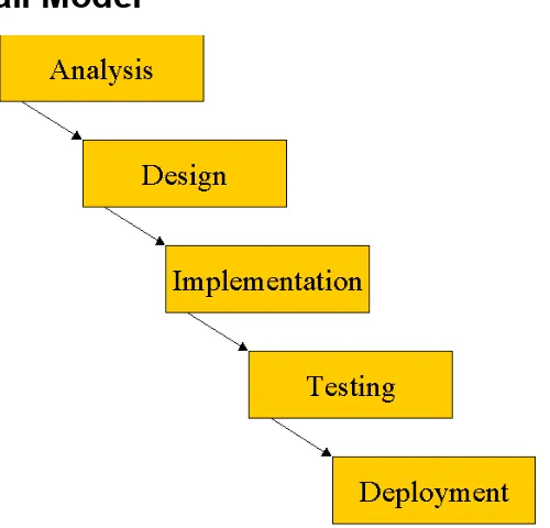
The waterfall model prescribes that each stage must be complete before the next stage can commence.
This simplistic (and easy to manage) process begins to break down as the complexity and size of the project increases. The main problems are:
• Even large systems must be fully understood and analysed before progress can be
made to the design stage. The complexity increases, and becomes overwhelming for the developers.
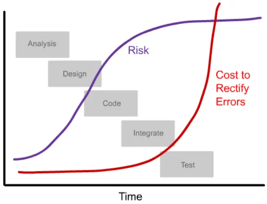
• Risk is pushed forward. Major problems often emerge at the latter stages of the
process – especially during system integration. Ironically, the cost to rectify errors increase exponentially as time progresses.
• On large projects, each stage will run for extremely long periods. A two-year long
testing stage is not necessarily a good recipe for staff retention!
Figure 3 –Over time on the waterfall, both the risks and the cost to rectify errors increase
Also, as the analysis phase is performed in a short burst at the outset of the project, we run a serious risk of failing to understand the customer’s requirements. Even if we follow a rigid requirements management procedure and sign off requirements with the customer, the chances are that by the end of Design, Coding, Integration and Testing, the final product will not necessarily be what the customer wanted.
months), then the waterfall is a valuable process. It is much better than chaotic hacking!
In summary, the waterfall model is easy to understand and simple to manage. But the advantages of the model begin to break down once the complexity of the project increases.
The Spiral Model
An alternative approach is the spiral model. In this approach, we attack the project in a series of short lifecycles, each one ending with a release of executable software:
Figure 4 - a spiral process. Here, the project has been divided into five phases, each phase building on the previous one and with a running release of software
produced at the end of each phase
With this approach:
• The team are able to work on the entire lifecycle (Analysis, Design, Code, Test)
rather than spending years on a single activity
• We can receive early and regular feedback from the customer, and spot potential
problems before going too far with development
• We can attack risks up-front. Particularly risky iterations (for example, an iteration
requiring the implementation of new and untested technology) can be developed first
The process is commonly associated with Rapid Application Development, which is considered by many to be a hacker's charter.
• The process is much more difficult to manage. The Waterfall Model fits in closely
with classic project management techniques such as Gantt charts, but spiral processes require a different approach.
To counteract the drawbacks of the spiral technical, let's look at a similar, but more formal approach called an Iterative, Incremental Framework.
Philippe Kruchten’s Whitepaper (reference [5], available from Rational Software’s website) explores the traps many managers are likely to face on their first iterative development.Iterative, Incremental Frameworks
The Iterative, Incremental Framework is a logical extension to the spiral model, but is more formal and rigorous. We will be following an Iterative, Incremental Framework through the rest of this course.
The framework is divided into four major phases: Inception; Elaboration; Construction and Transition. These phases are performed in sequence, but the phases must not be confused with the stages in the waterfall lifecycle. This section describes the phases and outlines the activities performed during each one.
Figure 5 - the four phases of an Iterative, Incremental Framework
Inception
The inception phase is concerned with establishing the scope of the project and generally defining a vision for the project. For a small project, this phase could be a simple chat over coffee and an agreement to proceed; on larger projects, a more thorough inception is necessary. Possible deliverables from this phase are:
• A Vision Document
• An initial exploration of the customer’s requirements • A first-cut project glossary (more on this later)
• A Business Case (including success criteria and a financial forecast, estimates of
the Return on Investment, etc)
A project plan
We’ll explore the inception phase in a little detail when we meet the case study in Chapter 4.
Elaboration
The purpose of elaboration is to analyse the problem, develop the project plan further, and eliminate the riskier areas of the project. By the end of the elaboration phase, we aim to have a general understanding of the entire project, even if it is not necessarily a
deep understanding (that comes later, and in small, manageable chunks).
Two of the UML models are often invaluable at this stage. The Use Case Model helps us to understand the customer’s requirements, and we can also use the Class Diagram
to explore the major concepts our customer understands. More on this shortly.
Construction
At the end of as many iterations as possible, we will aim to have a running system (albeit, of course, a very limited system in the early stages). These iterations are called
Increments, hence the name of the framework!
Transition
The final phase is concerned with moving the final product across to the customers. Typical activities in this phase include:
• Beta-releases for testing by the user community
• Factory testing, or running the product in parallel with the legacy system that the
product is replacing
• Data takeon (ie converting existing databases across to new formats, importing
data, etc)
• Training the new users
• Marketing, Distribution and Sales
The Transition phase should not be confused with the traditional test phase at the end of the waterfall model. At the start of Transition, a full, tested and running product should be available for the users. As listed above, some projects may require a beta-test stage, but the product should be pretty much complete before this phase happens.
How Many Iterations? How Long Should They Be?
A single iteration should typically last between 2 weeks and 2 months. Any more than two months leads to an increase in complexity and the inevitable “big bang”
integration stage, where many software components have to be integrated for the first time.
A bigger and more complex project should not automatically imply the need for longer iterations – this will increase the level of complexity the developers need to handle at any one time. Rather, a bigger project should require more iterations.
Some factors that should influence the iteration length include: (see Larman [2], pp447-448).
• Early development cycles may need to be longer. This gives developers a chance
to perform exploratory work on untested or new technology, or to define the infrastructure for the project.
• Novice staff
• Parallel developments teams
• Distributed (eg cross site) teams [note that Larman even includes in this category
any team where the members are not all located on the same floor, even if they are in the same building!]
software development tackled in the iteration should still be kept to a minimum to avoid our chief enemy, complexity overload.
Time Boxing
A radical approach to managing an iterative, incremental process is Time Boxing. This is a rigid approach which sets a fixed time period in which a particular iteration must be completed by.
If an iteration is not complete by the end of the timebox, the iteration ends anyway. The crucial activity associated with timeboxing is the review at the end of iteration. The review must explore the reasons for any delays, and must reschedule any unfinished work into future iterations.
Larman (ref [2]) gives details on how to implement timeboxing. One of his
recommendations is that the developers be responsible for (or at least, have a large say in) setting which requirements are covered in each iteration, as they are the ones who will have to meet the deadlines.
Implementing timeboxing is difficult. It requires a culture of extreme discipline through the entire project. It is extremely tempting to forgo the review and overstep the timebox if the iteration is “99%” complete when the deadline arrives. Once a project succumbs to temptation and one review is missed, the whole concept begins to fall apart. Many reviews are missed, future iterations planning becomes sloppy and chaos begins to set in.
Some managers assume that timeboxing prevents slippage. It does not. If an iteration is not complete once the timebox has expired, then the unfinished work must be reallocated to later iterations, and the iteration plans are reworked – this could include slipping the delivery date or adding more iterations. However, the benefits of
timeboxing are:
• The rigid structure enforces planning and replanning. Plans are not discarded once
the project begins to slip
• If timeboxes are enforced, there is less of a tendency for the project to descend
into chaos once problems emerge, as there is always a formal timebox review not too far away
• If panic sets in and developers start to furiously hack, the hacking is stemmed
once the review is held
Figure 7 - Possible timings for each phase. This example shows the length of each phase for a two year project.
The Rational Unified Process
The Rational Unified Process (the RUP) is the most famous example of an Iterative, Incremental Lifecycle in use at the moment. The RUP was developed by the same "Three Amigos" that developed the UML, so the RUP is very complementary to the UML.
Essentially, Rational appreciate that every project is different, with different needs. For example, for some projects, a tiny Inception Phase is appropriate, whereas for defence projects, the Inception phase could last years.
Figure 8 - Screenshot from RUP 2000 ( Rational Corp)
The precise advantages and disadvantages of the RUP are beyond the scope of this course. However, the core of the RUP, the Iterative, Incremental Lifecycle will be followed throughout this course to illustrate the key aspects of the UML models.
For more details on the RUP, Philippe Kruchten’s book The Rational Unified Process– An Introduction (ref 1) covers the subject in detail.Summary
An Iterative, Incremental Framework offers many benefits over traditional processes.
The Framework is divided into four phases - Inception, Elaboration, Construction, Transition.
Incremental development means to aim for running code at the end of as many iterations as possible.
Chapter 3
Object Orientation
In this chapter we will look at the concept of Object Orientation4 (OO). The Unified Modelling Language has been designed to support Object Orientation, and we'll be introducing Object Oriented concepts throughout this course. Before we begin looking at the UML in depth, however, it is worth introducing OO and looking at the
advantages that OO can offer to Software Development.
Structured Programming
First of all, let's examine (in very rough terms) how software systems are designed using the Structured (sometimes called Functional) approach.
In Structured Programming, the general method was to look at the problem, and then design a collection of functions that can carry out the required tasks. If these
functions are too large, then the functions are broken down until they are small enough to handle and understand. This is a process known as functional decomposition.
Most functions will require data of some kind to work on. The data in a functional system was usually held in some kind of database (or possibly held in memory as global variables).
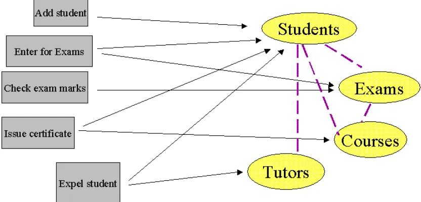
As a simple example, consider a college management system. This system holds the details of every student and tutor in the college. In addition, the system also stores information about the courses available at the college, and tracks which student is following which courses.
A possible functional design would be to write the following functions:
add_student5 enter_for_exam check_exam_marks issue_certificate expel_student 4
I'll use the phrase "Object Orientation" to denote Object Oriented Design and/or Object Oriented Programming
5
We would also need a data model to support these functions. We need to hold information about Students, Tutors, Exams and Courses, so we would design a database schema to hold this data.6
Figure 9 - Simple Database Schema. The dotted lines indicate where one set of data is dependent on another. For example, each student is taught by several
tutors.
The following diagram is a sketch of all the functions, together with the data, and lines have been drawn where a dependency exists:
Figure 10 - Plan of the functions, the data, and the dependencies
The problem with this approach is that if the problem we are tackling becomes too complex, the system becomes harder and harder to maintain. Taking the example above, what would happen if a requirement changes that leads to an alteration in the way in which Student data is handled?
As an example, imagine our system is running perfectly well, but we realise that storing the Student's date of birth with a two digit year was a bad idea. The obvious solution is to change the "Date of Birth" field in the Student table, from a two-digit year to a four-digit year.
The serious problem with this change is that we might have caused unexpected side effects to occur. The Exam data, the Course data and the Tutors data all depend (in some way) on the Student data, so we might have broken some functionality with our simple change. In addition, we might well have broken the add_student,
enter_for_exams, issue_certificate and expel_student functions. For example, add_student will certainly not work anymore, as it will be expecting a two digit year for "date of birth" rather than four.
So we have a large degree of potential knock-on problems. What is far, far worse is that in our program code, we cannot easily see what these dependencies actually are.
How many times have you changed a line of code in all innocence, without realising that you've inadvertently broken apparently unrelated functionality?
instead of two), the potential impacts of these minor changes had to be investigated in detail.7
The Object Orientated Approach
OO tries to lessen the impact of this problem by simply combining related data and functions into the same module.
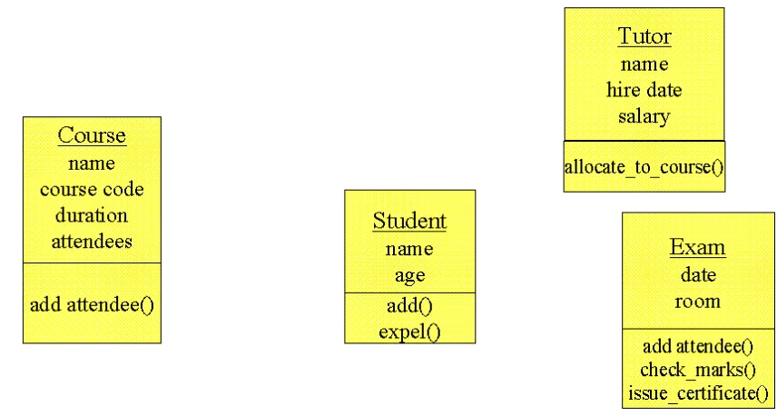
Looking at Figure 10 above, it is apparent that the data and functions are related. For example, the add_student and expel_student functions are clearly very closely related to the Student data.
The following figure shows the full grouping of the related data and functions, in the form of modules:
Figure 11 - Related data and functions placed in modules
A couple of points to note about this new modular system of programming:
• More than one instance of a single module can exist when the program is running.
Encapsulation
Crucially, only the instance that owns an item of data is allowed to modify or read it. So for example, an instance of the Tutor module cannot update or read the "age" data inside the Student module.
This concept is called Encapsulation, and enables the structure of the system to be far more robust, and avoid the situation as described previously, where a small change to a data member can lead to rippling changes.
With Encapsulation, the programmer of (say) the Student module can safely make changes to the data in the module, and rest assured that no other modules are dependent upon that data. The programmer might well need to update the functions inside the module, but at least the impact is isolated to the single module.
Objects
Throughout this chapter, I have referred to these collections of related data and functions as being "modules". However, if we look at the characteristics of these modules, we can see some real world parallels.
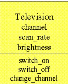
Objects in the real world can be characterised by two things: each real world object has data and behaviour. For example, a television is an object and posses data in the sense that it is tuned to a particular channel, the scan rate is set to a certain value, the contrast and brightness is a particular value and so on. The television object can also "do" things. The television can switch on and off, the channel can be changed, and so on.
We can represent this information in the same way as our previous software "modules":
Figure 12 - The data and behaviour of a television
In some sense, then, real world "objects" can be modelled in a similar way to the software modules we discussed earlier.
Since our software systems are solving real world problems (whether you are working on a College booking system, a Warehouse Management System or a Weapons Guidance System), we can identify the objects that exist in the real world problem, and easily convert them into software objects.
In other words, Object Orientation is a better abstraction of the Real World. In theory, this means that if the problem changes (ie the requirements change, as they always do), the solution should be easier to modify, as the mapping between the problem and solution is easier.
Terminology
The data for an object are generally called the Attributes of the object. The different behaviours of an object are called the Methods of the object. Methods are directly analogous to functions or procedures in programming languages.
The other big jargon term is Class. A class is simply a template for an object. A class describes what attributes and methods will exist for all instances of the class. In the college system we described in this chapter, we had a class called Student.
The attributes of the Student Class were name, age, etc. The methods were add() and expel(). In our code, we would only need to define this class once. Once the code is running, we can create instances of the class - ie, we can create objects of the class.
Each of these objects will represent a student, and each will have its own set of values of data.
The Object Oriented Strategy
Although this chapter has briefly touched on the benefits of Object Orientation (ie more robust systems, a better abstraction of the real world), we have left many
questions unanswered. How do we identify the objects we need when we're designing a system? What should the methods and attributes be? How big should a class be? I could go on! This course will take you through a software development using Object Orientation (and the UML), and will answer all these questions in full.
Summary
• Object Orientation is a slightly different way of thinking from the structured
approach
• We combine related data and behaviour into classes
• Our program then creates instances of the class, in the form of an object • Objects can collaborate with each other, by calling each other’s methods
Chapter 4
An Overview of the UML
Before we begin to look at the theory of the UML, we are going to take a very brief run through some of the major concepts of the UML.
The first thing to notice about the UML is that there are a lot of different diagrams (models) to get used to. The reason for this is that it is possible to look at a system from many different viewpoints. A software development will have many
stakeholders playing a part – for example:
• Analysts • Designers • Coders • Testers • QA
• The Customer • Technical Authors
All of these people are interested in different aspects of the system, and each of them require a different level of detail. For example, a coder needs to understand the design of the system and be able to convert the design to a low level code. By contrast, a technical writer is interested in the behaviour of the system as a whole, and needs to understand how the product functions. The UML attempts to provide a language so expressive that all stakeholders can benefit from at least one UML diagram.
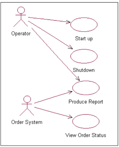
The Use Case Diagram
Figure 13 - The Use Case Diagram
A Use Case is a description of the system’s behaviour from a user’s viewpoint. This diagram is a valuable aid during analysis – developing Use Cases helps us to
understand requirements.
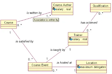
The Class Diagram
Figure 14 - The UML Class Diagram
Drawing Class Diagrams is an essential aspect of any Object Oriented Design method, so it isn’t surprising that the UML provides us with the appropriate syntax. We’ll see that we can use the Class Diagram at the analysis stage as well as design – we’ll use the Class Diagram syntax to draw a plan of the major concepts our customer
Collaboration Diagrams
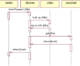
Figure 15 - The UML Collaboration Diagram
As we are developing object-oriented software, anything our software needs to do is going to be achieved by objects collaborating. We can draw a collaboration diagram to describe how we want the objects we build to collaborate.
Sequence Diagram
Figure 16 - A UML Sequence Diagram
The sequence diagram is, in fact, directly related to the collaboration diagram and displays the same information, but in a slightly different form. The dotted lines down the diagram indicate time, so what we can see here is a description of how the objects in our system interact over time.
State Diagrams
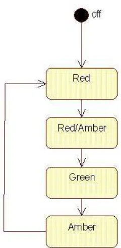
Figure 17 - A State Transition Diagram
Some objects can, at any particular time, be in a certain state. For example, a traffic light can be in any one of the following states:
Off, Red, Amber, Green
Sometimes, the sequence of transitions between states can be quite complex – in the above example, we would not want to be able to go from the “Green” state to the “Red” state (we’d cause accidents!).
Although the traffic light may seem like a trivial example, being sloppy with states can cause serious and embarrassing faults to occur in our software.
Take as a case in point – a gas bill is sent out to a customer who died four years ago – it really happens and it is because a programmer somewhere has not taken care with their state transitions.
Package Diagrams
Figure 18 - The UML Package Diagram
Component Diagrams
Figure 19 - The UML Component Diagram
The Component Diagram is similar to the package diagram - it allows us to notate how our system is split up, and what the dependencies between each module is. However, the Component Diagram emphasises the physical software components (files, headers, link libraries, executables, packages) rather than the logical
Deployment Diagrams
Figure 20 - A UML Deployment Diagram
The UML provides a model to allow us to plan how our software is going to be deployed. The diagram above shows a simple PC configuration, for example.
Summary
The UML provides many different models of a system. The following is a list of them, with a one sentence summary of the purpose of the model:
• Use Cases - “How will our system interact with the outside world?” • Class Diagram - “What objects do we need? How will they be related?” • Collaboration Diagram - “How will the objects interact?”
• Sequence Diagram - “How will the objects interact?” • State Diagram - “What states should our objects be in?”
Chapter 5
The Inception Phase
For the rest of this course, we are going to concentrate on a case study to describe how the UML is applied on real projects. We shall use the process outlined in Chapter 1, as in the diagram below:
Figure 21 - The process for our case study
In the diagram, I have included the name of each model we will produce at each stage. For example, at the design stage we will produce Class Diagrams, Interaction
Diagrams and State Diagrams. Of course, we’ll explore these diagrams throughout this course.
To recap the Inception Phase, the key activities in the phase are:
• Specify the vision for the product • Produce a business case
• Define the scope of the project
• Estimate the overall cost of the project
The size of the phase depends upon the project. An ecommerce project may well need to hit the market as quickly as possible, and the only activities in Inception might be to define the vision and get finance from a bank via the business plan.
Inception Elaboration Construction Transition
Short Use Cases Conceptual Model Prototypes Analysis Design Code Test Analysis Design Code Test
Full Use Cases Class Diagrams Interaction Diagrams State Diagrams Coded Use Cases
By contrast, a defence project could well require requirements analysis, project definition, previous studies, invites to tender, etc, etc. It all depends on the project.
On this course, we assume the inception phase is already complete. A business study has been produced (see separate document) that details our customer's initial
Chapter 6
The Elaboration Phase
In the Elaboration Phase, we are concerned with exploring the problem in detail, understanding the customer’s requirements and their business, and to develop the plan further.
We must get in to the correct frame of mind to attack this phase correctly. We must try not to get bogged down with too much detail – especially implementation details.
We need to have a very broad view of the system and understand system-wide issues. Kruchten (ref [1]) calls this a mile wide and inch deep view.
Prototyping
A key activity in the Elaboration Phase is the mitigation of risks. The sooner risks are identified and shot down, the lesser their impact will be on the project.
Prototyping difficult or problematic areas of the project are a tremendous help in the mitigation of risks. Given that we don't want to get bogged down in implementation and design at this phase, the prototypes should be very focussed, and explore just the area of concern.
Prototypes can be thrown away at the end of the exercise, or they can be reused during the construction phase.
Deliverables
Apart from prototypes, we are going to develop two UML models to help us towards our goal of understanding the problem as a whole.
The first model is the Use Case Model. This will help us to understand what the system needs to do, and what it should look like to the "outside world" (ie the users, or perhaps the systems it must interface to).
The second model is the Conceptual Model. This model allows us to capture, using UML, a graphical statement of the customer's problem. It will describe all of the major "concepts" in the customer's problem, and how they are related. To build this, we'll use the UML Class Diagram. We will use this Conceptual Model in the
Construction Phase to build our software classes and objects.
Figure 22 - Two UML models built during Elaboration
Summary
The Elaboration Phase is concerned with developing an understanding of the problem, without worrying about deep design details (except where risks are identified and prototypes are required).
Chapter 7
Use Case Modelling
A very powerful UML tool is the Use Case. A Use Case is simply a description of a set of interactions between a user and the system. By building up a collection of Use Cases, we can describe the entire system we are planning to create, in a very clear and concise manner.
Use cases are usually described using verb/noun combinations – for example, “Pay Bills”, “Update Payroll”, or “Create Account”.
For example, if we were writing a missile control system, typical Use Cases for the system might be “Fire Missiles”, or “Issue Countermeasures”.
Along with the name of the use case, we will provide a full textual description of the interactions that will occur between the user and the system. These textual
descriptions will generally become quite complicated, but the UML provides an astoundingly simple notation to represent a Use Case, as follows:
Figure 23 - Use Case Notation
Actors
Figure 24 - UML Notation for an Actor
Going further, actors can be more than just people. An actor can be anything external to the system that initiates a Use Case, such as another computer system. An actor could also possibly be a more abstract concept such as time, or a specific date. For example, we may have a use case called “Purge Old Orders” in an order processing system, and the initiating actor could be “Last Working Day”.
As we have noted, actors are related to Use Cases, in the sense that it is an actor that will initiate a particular use case. We can represent this on a Use Case diagram by connecting the actor to the use case:
Figure 25 - an Actor's relationship to a Use Case
that Use Cases are simple – almost too simple to worry about. Wrong. Use Cases are immensely powerful.
• Use Cases define the scope of the System. They enable us to visualise size and
scope of the entire development.
• Use Cases are very similar to requirements, but whilst requirements tend to be
vague, confusing, ambiguous and poorly written, the tighter structure of Use Cases tend to make them far more focused
• The “sum” of the use cases is the whole system. That means that anything not
covered by a use case is outside the boundary of the system we are developing. So the Use Case diagram is complete, with no holes.
• They allow for communication between the customer and developers (since the
diagram is so simple, anyone can understand it)
• Use Cases guide the development teams through the development process – we
shall see that Use Cases are the backbone of our development, and we refer to them in everything we do
• We’ll see that Use Cases provide a method for planning our development work,
and allow us to estimate how long the development will take
• Use Cases provide the basis for creating system tests • Finally, Use Cases help with the creation of user guides!
It is often claimed that Use Cases are simply an expression of the system
requirements. Anyone making this claim are clearly missing the point of Use Cases!8
Use Case Granularity
It can be difficult to decide upon the granularity of use cases – in a particular scenario, should each user-system interaction be a use case, or should the use case encapsulate all of the interactions? For example, let us consider the example of the ATM machine. We need to build the ATM system to allow a user to withdraw money. We might have the following series of common interactions in this scenario:
• enter card
• enter pin number • select amount required • confirm amount required • remove card
• take receipt
Should each of these steps – for example, “enter pin number” be a use case?
8
Figure 27 - A Useful Use Case Diagram?
This is a classic mistake in the construction of Use Cases. Here, we have generated a large number of small, almost inconsequential use cases. In any non-trivial system, we would end up with a huge number of Use Cases, and the complexity would become overwhelming.
To handle the complexity of even very large systems, we need to keep the Use Cases at a fairly “high level”. The best way to approach a Use Case is to keep the following rule-of-thumb in mind:
A Use Case should satisfy a goal for the actor
Applying this simple rule to our example above, we can ask the question “Is take receipt”, for example, the goal for our customer? Well, not really. It wouldn’t be the end of the world if the receipt wasn’t dispensed.
We will see later that Use Cases can be decomposed, but we must leave that step until we begin construction.
Use Case Descriptions
Each Use Case contains a full set of textual details about the interactions and scenarios contained within it.
The UML does not specify what the structure and contents of this document should be – this is up to individual projects/companies to specify9. We shall use the following template:
Use Case: Use Case Name
Short Description: A Brief Description of the Use Case
Pre-Conditions: A description of the conditions that must be satisfied before the use case is invoked
Post-Conditions : A description of what has happened at the end of the use case
Main Flow: A list of the system interactions that take place under the most common scenario. For example, for “withdraw money”, this would be “enter card, enter pin, etc...”
Alternate Flow(s): A description of possible alternative interactions.
Exception Flow(s): A description of possible scenarios where unexpected or unpredicted events have taken place
Figure 29 - Template for a Use Case Description
Use Cases at the Elaboration Phase
Our main job at the elaboration phase is to identify as many of the potential Use Cases as possible. Bearing in mind the “mile wide and inch deep” principle, our aim is to provide sketchy details of as many Use Cases as possible – but without the need to provide the full detail of each Use Case. This will help us to avoid complexity overload.
At this stage, a Use Case diagram (with actors and Use Cases), plus a brief description of each Use Case, will suffice. We can revisit the full details of the Use Cases during the construction phase. Once we have identified the use cases, we can cross reference Use Cases to requirements and ensure that we have caught all of the requirements.
If we identify some very risky Use Cases at this phase, however, it will be necessary to explore the details of the risky Use Cases. The production of prototypes at this stage will help mitigate the risks.
9
Finding Use Cases
One approach to finding Use Cases is via interviews with the potential users of the system. This is a difficult task, given that two people are likely to give two completely different views on what the system should do (even if they work for the same
company)!
Certainly, most developments will involve some degree of direct one-to-one user communication. However, given the difficulty of gaining a consistent view of what the system will need to do, another approach is becoming more popular – the
workshop.
Joint Requirements Planning Workshops (JRP)
The workshop approach pulls together a group of people interested in the system being developed (the stakeholders). Everyone in the group is invited to give their view of what the system needs to do.
Key to the success of these workshops is the facilitator. They lead the group by ensuring that the discussion sticks to the point, and that all the stakeholders are encouraged to put their views across, and that those views are
captured. Good facilitators are priceless!
A scribe will also be present, who will ensure that everything is documented. The scribe might work from paper, but a better method is to connect a CASE tool or drawing tool to a projector and capture the diagrams “live”.
The simplicity of the use case diagram is critical here – all stakeholders, even non-computer literate stakeholders, should be able to grasp the concept of the diagram with ease.
A simple method of attacking the workshop is:
1) Brainstorm all of the possible actors first
2) Next, brainstorm all of the possible Use Cases
The above advice is not a license to be sloppy, but remember the benefit of iterative processes is that everything doesn’t have to be 100% correct at every step!
Brainstorming Advice
Brainstorming is not as easy as it sounds; in fact I have rarely seen a well-executed brainstorm. The key things to remember when participating in a brainstorming session are:
• Document ALL ideas, no matter how outrageous or nonsensical they seem. Stupid
ideas might turn out to be very sensible ideas after all
• Also, silly ideas may trigger off more sensible ideas in other people’s mind – this
is called leapfrogging ideas
• Never evaluate or criticise ideas. This is a very hard rule to observe – we are
trying to break human nature here!
“mmm. No, that won’t work. We won’t bother to document that!”
The facilitator should keep on their toes and ensure that all ideas are captured, and that all of the group participate.
On the course, a Use Case Workshop will be carried out alongside our client.
Summary
Use Cases are a powerful way of modelling what the system needs to do.
They are an excellent way of expressing the system’s scope (What’s in = Sum of the Use Cases; what’s out = The Actors).
We need to keep an eye on the granularity of the Use Cases to contain complexity.
Chapter 8
Conceptual Modelling
Conceptual Modelling (sometimes called Domain Modelling) is the activity of finding out which concepts are important to our system. This process helps us to understand the problem further, and develop a better awareness of our customer’s business.
Once again, the UML does not tell us how or when to do Domain Modelling, but it does provide us with the syntax to express the model. The model we are going to use is the class diagram.
Figure 30 - A UML Class Diagram
On the conceptual model, we aim to capture all of the concepts or ideas that the customer recognises. For example, some good examples of concepts would be:
• Lift in a lift control system
• Order in a home shopping system
• Footballer in a football transfers system (or a PlayStation football game!) • Trainer in a stock management system for a shoe shop
• Room in a room booking system
Some very bad examples of concepts are:
• OrderPurgeDaemon the process that regularly deletes old orders from the system • EventTrigger – the special process that waits for 5 minutes and then tells the
system to wake up and do something
• CustomerDetailsForm – the window that asks for details of the new customer in
a shopping system
• DbArchiveTable – the database table holding a list of all old orders
These are bad concepts, because they are focussing on design – the solution, and not the problem. In the DbArchiveTable example, we are already tying ourselves down to a relational database solution. What if it turns out later that it is more efficient,
cheaper, and perfectly acceptable to use a simple text file?
The best rule of thumb here is:
If the customer doesn’t understand the concept, it probably isn’t a concept!
Designers hate the conceptual step – they cannot wait to crack on with design. We shall see, however, that the conceptual model will slowly transform into a full design class diagram as we move through the construction phase.
Finding Concepts
I recommend a similar approach to finding Use Cases – a workshop is best – once again, with as many interested stakeholders as possible.
Brainstorm suggestions for concepts, capture all the suggestions. Once brainstorming is complete, work as a group to discuss and justify each suggestion. Apply the rule of thumb that the customer must understand the concept, and discard any that don’t apply to the problem, and discard any that are touching on design.
Extracting Concepts From Requirements
The requirements document is a good source of concepts. Craig Larman (ref [2]) suggests the following candidate concepts from the requirements:
• Physical or tangible objects • Places
• Transactions
• Roles of People (eg Customer, Sales Clerk) • Containers for other Concepts
Abstract Nouns (eg Thirst)
• Organisations
• Event (eg Emergency) • Rules/Policies
• Records/Logs
A couple of points here. First of all, gathering concepts in a mechanical manner is poor practise. The above list are good suggestions, but it would be wrong to think that it is enough to run through the requirements document with a highlighter pen, pulling out some phrases and setting them as concepts. You must have input from the
customer.
Secondly, many practitioners suggest extracting noun phrases from documents. This approach has been is common usage for almost 20 years, and although there is nothing inherently wrong with it, I hate the implication that mechanically searching for nouns will result in a good list of concepts/classes. Sadly, the English language is far too ambiguous to allow for such a mechanical approach. I’ll say it again – input from the customer is essential!
The Conceptual Model in the UML
Now that we’ve seen how to discover the concepts, we need to look how to capture the concepts in the UML. We’ll use the core aspects of the class diagram.
We represent our concept in a simple box, with the title of the concept (by convention, capitalised) at the top of the box.
Figure 31 - The "Race" concept captured in UML (for a Horse Racing System)
Figure 32 - The UML captures the attributes and behaviour of a concept
In the example above, we have decided that every runner will have two attributes – “Name” and “Age”. We leave the bottom area blank until later, when we decide what a “Runner” is able to do.
Finding Attributes
We need to determine what the attributes of each concept are – and again, a
brainstorming session with the stakeholders is probably the best way to achieve this.
Often, arguments arise over whether or not an attribute should become a concept on its own. For example, lets say we are working on a Staff Management system. We have identified that one concept would be “Manager”. A suggestion for an attribute might be “salary”, as follows:
Figure 33 - Manager concept, with the attribute "Salary"
That looks fine, but someone might argue that “Salary” is also a concept. So, should we make promote it from an attribute to a concept?
I have seen many modelling sessions descend into chaotic arguments over issues like this one, and my advice is to simply not worry about it: if in doubt, make it another concept. These kind of problems usually resolve themselves later on anyway, and it really isn’t worth wasting valuable modelling time on arguments!
Figure 34 - Manager and Salary, two separate concepts
Runner
Name
Age
Manager
salary
Guidelines for Finding Attributes
The following rules of thumb may be helpful when deciding between attributes and concepts – but heed the advice above and don’t worry too much about the distinction.
If in doubt, make it a concept!
• Single valued strings or numbers are usually attributes10
• If a property of a concept cannot do anything, it might be an attribute - eg for the
manager concept, “Name” clearly sounds like an attribute. “Company Car” sounds like a concept, because we need to store information about each car such as the registration number and colour.
Associations
The next step is to decide how our concepts are related. In any non-trivial system, at least some of the concepts are going to have some kind of conceptual relationship with other concepts. For example, back to our Staff Management system, given the following two concepts:
Figure 35 - Manager and Company Car Concepts
These concepts are related, because in the company we are developing a system for, each Manager drives a Company Car.
We can express this relationship in the UML by connecting the two concepts together with a single line (called an association), as follows:
In this example, we are saying that “Each Manager Drives 1 Company Car”, and (going from right to left) “Each Company Car is driven by 1 Manager”.
Figure 37 - Another Association Example
In the above example, we see that “Each Manager manages 1 or more staff members”; and (going the other way), “Each Staff Member is managed by 1 Manager”.
Every association should work like this – when reading the association back in English, the English sentence should make perfect sense (especially to the customer). When deciding upon association names, avoid weak names like “has” or “is
associated to” – using such weak language could easily hide problems or errors that would otherwise have been uncovered if the association name was more meaningful.
Possible Cardinalities
Basically, there are no restrictions on the cardinalities you are able to specify. The following diagram lists some examples, although this list is by no means exhaustive. The * notation denotes "many". Note the slight difference between "*" and "1..*". The former is a vague "many", meaning that perhaps any number of concepts are allowed, or maybe we haven't made the decision yet. The latter is more concrete, implying that one or more are allowed.
Figure 38 - Example Cardinalities
Building the Complete Model
Finally, let’s look at a methodical system for determining the associations between the concepts. Assume we have completed the brainstorm session and uncovered several concepts for the Staff Management system. The set of concepts are in the figure below (I’ve omitted the attributes for clarity).
Manager name
1
manages
Staff Member
Figure 39 - Set of Concepts for Staff Management
The best way to proceed is to “fix” one concept, say “Manager” and consider every other concept in turn. Ask yourself “are these two concepts related?”, and if so, immediately decide on the name of the association, and the cardinality…
“
Are more staff membersManager and Staff Member. related? Yes, Each Manager manages 1 or Manager and Company Car? Yes, Each Manager drives 1 company car.Manager and Pension? Yes, Each Manager contributes to 1 pension”
”
Figure 40 - The simple conceptual model, completed
When building the model, it is important to remember that associations are less important than attributes. Any missing associations will be easily picked up during design, but it is harder to spot missing attributes.
Furthermore, it can be tempting to overspecify the map of associations "just in case", and end up with quite a confusing and complex diagram. So a good rule of thumb is to concentrate on concepts and attributes, and try to fix the most obvious associations.
At the end of the modelling, the diagram should make sense to the customer when you "read back" the diagram in English.
Summary
Conceptual Models provide a powerful way of investigating the problem further.
Later on, we’ll expand our model into the design aspects.
This model will eventually be one of the key inputs when we build the code.
Chapter 9
Ranking Use Cases
We have a lot of work ahead – how can we divide up the work into the simple, manageable iterations that we described in the early stages of the course?
The answer is by focusing on our Use Cases. In each iteration, we design, code and test just a few Use Cases. So effectively, we have already decided how we are going to divide up the work into iterations – the only thing we haven’t done yet is to decide upon the order in which we will attack them.
To plan the order, we allocate each Use Case a rank. The rank is simply a number that indicates which iteration the Use Case will be developed in. Any good Case Tool should allow the rank to be captured as part of the model.
There are no hard and fast rules on how to allocate ranks. Experience and knowledge of software development plays a large part in setting the rank. Here are some
guidelines on which Use Cases should be allocated a higher rank (ie to be developed earlier rather than later):
• Risky Use Cases
• Major Architectural Use Cases
• Use Cases exercising large areas of system functionality • Use Cases requiring extensive research, or new technologies • “Quick Wins”
• Large payoffs for the customer
Some Use Cases will need to be developed over several iterations. This could be because the Use Case is simply too big to design, code and test in one iteration, or it could be because the Use Case depends upon many other Use Cases being complete (“Start Up” is a classic example of this).
Summary
Use Cases allow us to schedule the work across our multiple iterations
We rank the Use Cases to determine the order in which they are attacked
Ranking Use Cases is based on your own knowledge and experience.
Some rules of thumb will help in your early days.
Chapter 10
The Construction Phase
In this short chapter, we’ll take stock of what we’ve done, and what needs to be done next.
In the Elaboration Phase, we needed to understand the problem as fully as possible, without going into too much detail. We built a Use Case Model, and created as many Use Cases as possible. We did not fill in the complete details of the Use Cases, instead we supplied a very brief description of each one.
The next step was to build a conceptual model, where we captured the concepts driving our development. This conceptual model will provide us with the foundations of the design.
We then ranked each of our Use Cases, and in doing so, we have planned the order of the Use Case development.
This completes our Elaboration Phase. A complete review of the phase would be held, and a Go/No Go decision needs to be made. After it, we may have discovered during Elaboration that we really cannot provide a solution for our customer – better to find out now than at the end of coding!
Construction
Now that we are in the Construction Phase, we need to build the product, and take the system to the state where it can be delivered to the user community.
Recall that our general plan of attack is to follow a series of short waterfalls, with a small number of Use Cases developed in each iteration. At the end of each iteration, we will review progress, and preferably timebox the iteration.
Then the iteration is tested (ie all of the use cases need to be demonstrably working), and then we reach the review.
Summary
Chapter 11
The Construction Phase : Analysis
The first stage of the construction phase is Analysis. We need to revisit the Use Cases we are building in this iteration, and enhance and expand those Use Cases. By
concentrating on the full detail of only a few Use Cases per iteration, we are reducing the amount of complexity we have to manage at any one time.
Figure 41 - Analysis Phase of Construction
Remember that even though we are now in construction, we are still at the analysis stage – albeit a more detailed analysis than the analysis we did in elaboration. Therefore, we must bear in mind that we are only concerned with the problem, and not the solution. So we are looking at what the system has to do, without worrying about how it will do it.
Back to the Use Cases
Inception Elaboration Construction Transition
Short Use Cases Conceptual Model Prototypes Analysis Design Code Test Analysis Design Code Test
Requirements R2.3; R7.1 Pre-Conditions: Post-Conditions Main Flow: Alternate Flow(s): Exception Flow(s):
Figure 42 - The Short Use Case, Place Bet
The diagram above shows an example Short Use Case. Each of the headings needs to be filled in. The best way to explain how to fill in the headings is with a specific example, so lets have a look at the Place Bet Use Case:
1. Pre-Conditions
This section describes the system conditions which must be satisfied before the Use Case can actually take place. In the Place Bet, example, a good pre-condition could be:
“The User Has Successfully Logged In”.
Clearly, the betting system needs to validate customers before they can start
gambling. However, the validation of the user is not part of this Use Case, so we must ensure that this condition has been satisfied before the betting takes place.
2. Post Conditions
The post conditions describe the state the system will be in at the end of the Use Case. The post-condition is conventionally written in past tense language. So in our Place Bet example, the post condition would be:
“The User placed a bet and the bet was recorded by the system”
There can be more than one post condition, depending on the outcome of the Use Case. These different post conditions are described using “if then” language”. Eg “If a new customer, then a customer account was created. If an existing customer, then the customer details were updated”.
3. Main Flow
The main flow section describes the most likely, or the most conventional, flow of events through the Use Case. Clearly, in the Place Bet Use Case, many things can go wrong. Perhaps the user cancels the transaction. Maybe the user has insufficient funds to place a bet. These are all events we have to consider, but really, the most
conventional flow through this use case is going to be a user successfully placing a bet.
(1) On initiation of Place Bet by the gambler, a list of the day’s races are requested from the system, and (2) the list of races are displayed
(3) The Gambler chooses the race to bet on [A1] and (4) the system presents a list of the runners for that race
(5) The Gambler chooses the horse to bet on [A1] and enters the required stake [E1] (6) The User Confirms the transaction and (7) the system displays a confirmation message
Notice that every actor/system interaction is broken down into steps. In this case, there are seven steps in the main flow of the Use Case. The [A1] and [E1] notation will be explained in a moment, when we look at Alternate Flows and Exception Flows.
Alternate Flows
Alternate flows are simply less common (but legitimate) flows through the Use Case. The alternate flow will typically share many steps with the main flow, so we can notate the point in the main flow where the alternate flow takes over. We have done this in step (3) of the main flow above, through the [A1] notation. This is because when the user chooses the race to bet on, they can cancel the transaction. They can also cancel the transaction at step 5, when they are required to enter the stake.
“(A1) The User Cancels the Transaction Post Condition -> No bets were placed”
In this case, the Alternate flow has resulted in a change to the post condition – no bets were placed.11
Exception Flows
Finally, the exception flow describes exceptional situations. In other words, a flow where an error has occurred, or an event that couldn’t have otherwise been predicted.
In our place bet example, we could have the following exception:
The Complete Use Case
Use Case Place Bet
Short Description: The user places a bet on a particular horse after choosing a race
Actors: Gambler
Requirements R2.3; R7.1
Pre-Conditions: The User has successfully logged in
Post-Conditions: A bet was placed and the bet was recorded by the system Main Flow:
(1) On initiation of Place Bet by the gambler, a list of the day’s races are requested from the system, and (2) the list of races are displayed
(3) The Gambler chooses the race to bet on [A1] and (4) the system presents a list of the runners for that race
(5) The Gambler chooses the horse to bet on [A1] and enters the required stake [E1]
(6) The User Confirms the transaction and (7) the system displays a confirmation message
Alternate Flow(s):
(A1) The gambler cancels the transaction.
Post Condition -> No bets were placed
Exception Flow(s):
(E1) The user’s credit is not sufficient to fund the bet. The user is informed and the Use Case Terminates
Figure 43 - Full Use Case Description
The UML Sequence Diagram
Producing the Use Case Descriptions is difficult. Many people find the distinction between analysis and design especially difficult – often the Use Case descriptions become littered with design decisions.
Here’s an example from the Place Bet Use Case:
“The User selects the race to bet on. The system interrogates the race database and compiles an array of runners for the race.”
This is a poor Use Case description. By talking about the race database and introducing arrays, we are tying ourselves down to specific design decisions.
When building the Use Cases, we need to treat the system as a “black box”, which can accept requests from actors and return results to the actor. We are not concerned (yet) with how the black box fulfils that request.
diagram can be used in analysis to help us with this “black box” analysis of the system. Here’s how the diagram works:
1
We place the actor on the left of the diagram, and on the right of the diagram, we represent the entire system as a single box.2
Next, we add vertical “timelines”. The lines represent the passage of time in the downward direction3
Interactions between the user and the system are represented as a line with an arrow between the system and the actor.4
Continue adding the interactions down the timeline.The long boxes down the timeline indicate when the system of the actor is “active”. This notation is more important when we draw sequence diagrams in design – for now, it doesn’t really matter(these boxes were added by our CASE tool).
Once the System Sequence Diagram is complete, it is a fairly simple