Wiley Publishing, Inc. 10475 Crosspoint Boulevard Indianapolis, IN 46256 www.wiley.com
Copyright © 2006 by Wiley Publishing, Inc., Indianapolis, Indiana Published simultaneously in Canada
ISBN-13: 978-0-471-78127-1 ISBN-10: 0-471-78127-4
Manufactured in the United States of America 10 9 8 7 6 5 4 3 2 1
1MA/SU/QX/QW/IN
No part of this publication may be reproduced, stored in a retrieval system or transmitted in any form or by any means, electronic, mechanical, photocopying, recording, scanning or otherwise, except as permitted under Sections 107 or 108 of the 1976 United States Copyright Act, without either the prior written permission of the Publisher, or authorization through payment of the appropriate per-copy fee to the Copyright Clearance Center, 222 Rosewood Drive, Danvers, MA 01923, (978) 750-8400, fax (978) 646-8600. Requests to the Publisher for permission should be addressed to the Legal Department, Wiley Publishing, Inc., 10475 Crosspoint Blvd., Indianapolis, IN 46256, (317) 572-3447, fax (317) 572-4355, or online at http://www.wiley.com/go/permissions.
Limit of Liability/Disclaimer of Warranty:The publisher and the author make no representations or warranties with respect to the accuracy or completeness of the contents of this work and specifically dis-claim all warranties, including without limitation warranties of fitness for a particular purpose. No warranty may be created or extended by sales or promotional materials. The advice and strategies con-tained herein may not be suitable for every situation. This work is sold with the understanding that the publisher is not engaged in rendering legal, accounting, or other professional services. If professional assistance is required, the services of a competent professional person should be sought. Neither the publisher nor the author shall be liable for damages arising herefrom. The fact that an organization or Website is referred to in this work as a citation and/or a potential source of further information does not mean that the author or the publisher endorses the information the organization or Website may provide or recommendations it may make. Further, readers should be aware that Internet Websites listed in this work may have changed or disappeared between when this work was written and when it is read. For general information on our other products and services or to obtain technical support, please con-tact our Customer Care Department within the U.S. at (800) 762-2974, outside the U.S. at (317) 572-3993 or fax (317) 572-4002.
Library of Congress Cataloging-in-Publication Data Edwards, James,
1962-Nortel guide to VPN routing / James Edwards, Richard Bramante, Al Martin. p. cm.
“Wiley Technology Publishing.” Includes index.
ISBN-13: 978-0-471-78127-1 (cloth) ISBN-10: 0-471-78127-4 (cloth)
1. Routing (Computer network management) 2. Extranets (Computer networks) I. Bramante, Richard, 1944- II. Martin, Al, 1964- III. Title.
TK5105.543.E39 2006 004.6’2--dc22
2006011213
Trademarks:Wiley and related trade dress are registered trademarks of Wiley Publishing, Inc., in the United States and other countries, and may not be used without written permission. All other trade-marks are the property of their respective owners. Wiley Publishing, Inc., is not associated with any product or vendor mentioned in this book.
Natasia, Shaun, Nick, Emily, and Samantha. For the support, pride, admiration, love, laughter, life lessons, and so much more that they give to me each
and every day of my life.
—Jim Edwards
This book is dedicated to my beloved departed wife, Barbara, who showed great courage and perseverance in facing and
battling the illnesses that eventually took her from this life. Her constant encouragement in whatever I wanted to pursue is not forgotten, nor will her memory fade. For without her in my life, I would not have my son, Richard, who is a source of joy and pride.
I thank him and his loving wife, Michelle, for the three beautiful grandchildren they blessed me with, my three amigos,
Vanessa, Ethan, and Olivia.
James Edwards(Nashua, NH) is a Nortel Networks Certified Support Spe-cialist (NNCSS) in VPN Routers. Working in the Premium Support Group (consisting of Nortel’s largest Enterprise customers), he has extensive experi-ence with many Nortel products, in particular in support for VPN Routers for the last two years. Jim has previous technical writing experience and is also author of Nortel Networks: A Beginner’s Guide(McGraw-Hill, 2001).
Richard Bramante(Tewksbury, MA) is a Nortel Networks Certified Support Specialist (NNCSS) in VPN Routers. Richard has been in Nortel VPN Router support for three years and prior to this, was a technology lead on the Instant Internet (now part of the VPN Router portfolio) for four years. He has previ-ous technical writing experience drafting functional specifications and testing procedures for various technologies and devices.
About the Authors
Executive Editor
Carol Long
Development Editor
Kevin Shafer
Production Editor
Angela Smith
Copy Editor
Nancy Rapoport
Editorial Manager
Mary Beth Wakefield
Production Manager
Tim Tate
Vice President and Executive Group Publisher
Richard Swadley
Vice President and Executive Publisher
Joseph B. Wikert
Project Coordinator
Jennifer Theriot
Graphics and Production Specialists
Jennifer Click Lauren Goddard Denny Hager
Stephanie D. Jumper Lynsey Osborn Heather Ryan Alicia B. South
Quality Control Technician
Leeann Harney Joe Niesen
Proofreading and Indexing
Techbooks
Cover Image
Kristin Corley
Credits
Chapter 1 Networking and VPN Basics 1
Networking Basics 2
The OSI Reference Model 2
The Application Layer (Layer 7) 3 The Presentation Layer (Layer 6) 4 The Session Layer (Layer 5) 4 The Transport Layer (Layer 4) 4 The Network Layer (Layer 3) 5 The Data Link Layer (Layer 2) 6 The Physical Layer (Layer 1) 6 Overview of a Local Area Network 7 Overview of a Wide Area Network 8 Media Access Control Addressing 8 Internet Protocol Addressing 9
IP Address Classes 10
Class A Addresses 10
Class B Addresses 11
Class C Addresses 11
Class D Addresses 11
Protocols and Other Standards 12
Internet Protocol 12
Interior Gateway Protocol 13
Exterior Gateway Protocol 14
Routing Information Protocol 14
Open Shortest Path First 15
Virtual Router Redundancy Protocol 16
Digital Subscriber Line 16
Contents
Integrated Services Digital Network 17 Lightweight Directory Access Protocol 18 Remote Authentication Dial-In User Service 18
Networking Hardware 19
Random Access Memory 19
Modem 19
Channel Service Unit/Data Service Unit 20
Computer Workstations 20
Dial Access to a Single Workstation 25
Remote Access System 25
VPN Tunneling Protocols and Standards 30
Secure Sockets Layer 30 Layer 2 Tunneling Protocol 36 Generic Routing Encapsulation 37
Summary 38
Chapter 2 The Nortel VPN Router 39
The Nortel VPN Router Portfolio 40
Modules and Interfaces 41
SSL VPN Module 1000 41
Hardware Interface Options 42
Peripheral Component Interconnect Expansion Slots 42
10/100Base-T Ethernet 42
CSU/DSU 43
T1/E1 43
ADSL 44
Serial Interfaces (V.35, X.21, RS-232) 44
V.90 Dial Access Modem 45
High Speed Serial Interface 45 Encryption Accelerator Modules 45
Console Port (DB-9) 45
Nortel VPN Router Solutions 46
VPN Router 100 48
Overview 50
Technical Specifications 50
VPN Router 200 Series 50
VPN Router 221 50
VPN Router 251 52
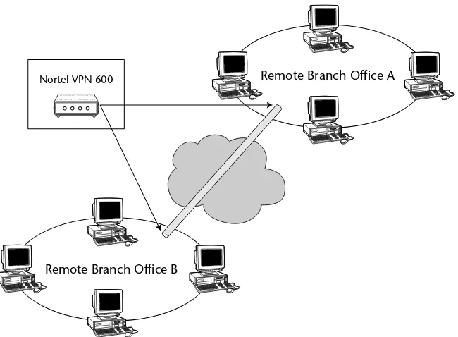
VPN Router 600 53
VPN Router 1000 Series 55
VPN Router 1010 55
VPN Router 1050 57
VPN Router 1100 58
VPN Router 1700 Series 59
VPN Router 1700 60
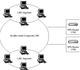
VPN Router 1740 61
VPN Router 1750 62
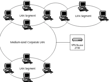
VPN Router 2700 63
Overview 64
VPN Router 5000 66
Overview 66
VPN Router Features Comparison 67
Deployment Examples 70
Branch Office Tunnel VPN Solution 70
Extranet VPN Solution 71
Remote Access VPN Solution 72
Summary 74
Chapter 3 The Nortel VPN Router Software Overview 75
Nortel VPN Software 76
Secure Sockets Layer Services 79
VPN Router Software Version 6.00 79
Memory Requirements 80
Optional Software Licenses 80
Advanced Router License Key 80 Contivity Stateful Firewall License Key 81 Additional VPN Tunnel Support License Key 81 Features Introduced in VPN Router Version 6.00 81
Loading, Verifying, and Upgrading the VPN Router Software 82
Release Notes 83
Loading a New Version of VPN Router Software 83
Removing Unused Versions 102
VPN Client Software 106
Installing the VPN Client Software 106
Release Notes 107
Installing the VPN Client 107 Upgrading the VPN Client Software 113 Uninstalling the Existing Version of VPN Client Software 113
Installing the Upgrade 115
Starting the VPN Client 122
The VPN Client Connection Wizard Process 125 Selecting Username and Password Authentication Type 126 Selecting Hardware or Software Token Card
Authentication Type 130
Summary 132
Chapter 4 The Nortel VPN Router in the Network 133
What Is a Virtual Private Network? 133
Tunneling Basics 135
Branch Office Tunnel 136
Aggressive Mode Branch Office Tunnel 138
User/Client Tunnel 141
PC-Based VPN Tunnels 142
VPN-Enabled Device Acting in Client Mode 145 Small Office or Home Office 148
DMZ Creation and Usages 154
The Regional Office 158
Nortel 100 VPN Router Added to Existing
Regional Office Network 160
Upgrading a Regional Office to VPN Technology 162
The Central Office 164
The VPN Router as an Access Point 166 Client Access to the Corporate Network 168 Client Load Balancing and Failover 171 Corporate User Access to the Internet 172
Backup Interface Services 173
Interface Group Fails 175
Ping Failure 175 Time of Day or Day of the Week 176
Placement in the Network 177 Network Administration of VPN Routers 180
Direct Access 181
Chapter 5 Management Options and Overview 185
Serial Port Management 186
Command Line Interface 187
Accessing the CLI Through a Telnet Session 187 Accessing the CLI Through the Serial Port 188
CLI Command Modes 188
Checking the Current Status of Your VPN Router 206
Logs 206
Configuration Log 206
Event Log 208
Security Log 210
System Log 212
VPN Router System Status Tools 214
Other VPN Router Tools 218
Lightweight Directory Access Protocol 222 Remote Authentication Dial-In User Service 222
Automatic System Backups 223
Using Remote Authentication Dial-in User Service 242
Enabling RADIUS Authentication 242
SSL Encryption with LDAP Server 251 LDAP Certificate Installation 251
LDAP Special Characters 252
External LDAP Proxy 252
Tunnel Certificates 253
Using Public Key Infrastructure 254
PKI Setup 254
CA and X.509 Certificates 254
Loading Certificates 255
Requesting a Server Certificate 255 Server Certificates Using CMP 255 Trusted CA Certificate Installation 260 Trusted CA Certificate Settings 261 Certificate Revocation List Configuration 264
CRL Server Configuration 265
CRL Retrieval 268 Enabling Certificate Use for Tunnels 268 Identifying Individual Users with Certificates 269 Identifying Branch Offices with Certificates 270
IPSec Authentication 271
L2TP/IPSec Authentication 273
Adding L2TP Access Concentrators 274
Summary 275 Stateful Firewall Manager System Requirements 284
Enabling Firewall Options 284
Enabling the Stateful Firewall Feature 285 Connection Limitation and Logging 286 Application-Specific Logging 286 Remote Logging of Firewall Events 287 Anti-Spoofing Configuration 288 Malicious Scan Detection Configuration 289
Firewall Policies 290
Firewall Policy Creation and Editing 290
Policy Creation 290
Creating a New Policy 305
Firewall Examples 308
Residential Example 309
Business Example 309
Filters 311
Adding / Editing Filters 311
Next Hop Traffic Filter 314
NAT 315
Types of Address Translation 315
Dynamic Many-to-One NAT 316
Port Restricted Cone NAT 323
Symmetric NAT 324
NAT Traversal 325
NAT and VoIP 326
Address/Port Discovery 327
NAT Usage 327
Branch Office Tunnel NAT 328
Interface NAT 329
Dynamic Routing Protocols 329
Configuring a NAT Policy 330
NAT Policy Sets 330
Creating Rules 331
NAT ALG for SIP 331
Application Level Gateways 331 Configuring NAT ALG for SIP 332
Firewall SIP ALG 332
Hairpinning 332
Hairpinning with SIP 333
Hairpinning with a UNIStim Call Server 333 Hairpinning with a STUN Server 333
Chapter 8 Overview of Ethernet LANs and Network Routing 337
Ethernet Networking 338
Basic Physical Topology Types 339
Bus Topology 339
Star Topology 339
Carrier Sense Multiple Access with Collision Detection 340
Ethernet Variants 341
Media Access Control (MAC Addressing) 350 Internet Protocol (IP Addressing) 351 Address Resolution Protocol 351 Reverse Address Resolution Protocol 353
Virtual Local Area Network 353
Network Routing 355
Open Shortest Path First 370
OSPF History 371
OSPF Considerations 371
Router Unique Name 372
Adjacencies 372
OSPF Areas 373
Path Vector Routing Algorithm 380
Virtual Router Redundancy Protocol 381
VRRP Failover 382
Summary 382
Chapter 9 Tunneling, VoIP, and Other Features 385
Layer 2 Forwarding 386
Point-to-Point Tunneling Protocol 390 Layer 2 Tunneling Protocol 396 IP Security Tunneling Protocol 400
Quality of Service 405
Voice over IP 410
Point-to-Point Protocol over Ethernet 413 Client Address Redistribution 416
Circuitless IP 418
Backup Interface Services 419
Summary 421
Chapter 10 The Nortel VPN Client 423
Overview of the Nortel VPN Client 424
Operating System Compatibility 424 Supported Operating Systems 425
Operating Systems Supported Prior to the
Nortel VPN Client Version 4.91 426 Operating Systems Supported in the Nortel
VPN Client Version 6.01 426
Optional Licensing Operating Systems Supported 426
Installing the Nortel VPN Client 426 Using the Nortel VPN Client 433
Status and Monitoring 434
VPN Client Main Menu Items 435
The File Menu Option 436
The Edit Menu Option 437
The Options Menu Option 437
Nortel VPN Client Customization 440
VPN Custom Client Installation Modes 441 VPN Customer Client Group Profiles Overview 442 VPN Custom Client Icons and Custom Bitmaps 442
VPN Client Event Logging and Keepalives Overview 442
VPN Client Event Log 443
VPN Client Keepalive 445
Internet Security Association and Key Management
Protocol Keepalive 446
Network Address Translation Traversal Keepalive 446
Silent Keepalive 447
Support for All Zeros Addressing in Inverse Split Mode 455
TunnelGuard 455
TunnelGuard Daemon 455
Software Requirement Set Builder 456
TunnelGuard Agent 456
Chapter 11 VPN Router Administration Lab Exercises 463
Installing the VPN Client Software 464
Lab Requirements 464
Lab Setup 464
Lab Summary 465
Initial Setup of the Nortel VPN Router 465
Lab Requirements 465
Lab Setup 466
Lab Summary 468
Enabling and Using VPN Client Logging 468
Configuring Users 471
Configuring a Peer-to-Peer Branch Office Tunnel 479
Lab Requirements 479
Configuring Network Time Protocol 484
Lab Requirements 484
Configuring the Nortel 100 VPN Router 492
Lab Requirements 492
Lab Setup 493
Basic Configuration Lab 493
Tunneling Lab 495
Lab Summary 502
Configuring CLIP for Management IP Address 502
Lab Requirements 503
Lab Setup 503
Lab Summary 505
Configuring Administrator User Tunnels 505
Lab Requirements 505
Lab Setup 506
Configuring Syslog Server 512
Lab Requirements 512
Lab Setup 513
Lab Summary 515
Configuring User IP Address Pools 515
Lab Requirements 515
Lab Setup 516
Configuring User IP Address Assignment Using DHCP Lab 516 Configuring User IP Address Assignment Using
Address Pool Lab 519
Lab Summary 521
Client Address Redistribution Configuration 521
Lab Requirements 522
Lab Setup 522
Lab Summary 526
Summary 527
Chapter 12 Troubleshooting Overview 529
Overview of Network Troubleshooting 530
Logical Steps 530
Make Sure You Understand the Problem 530
Diagnosing the Problem 531
Nortel VPN Router Troubleshooting 545
Tools 546
VPN Router System Recovery 553
System Recovery for Disk-Based Versions 554
System Restore Option 555
Reformat Hard Disk Option 557
Perform File Maintenance option 557
View Event Log Option 557
Restart System 558
System Recovery for Diskless Versions 558
System Restore Option 559
Reformat Hard Disk Option 559
Apply New Version Option 559
Perform File Maintenance Option 559
View Event Log Option 561
Use of the Nortel VPN Router Reporting Utilities 562
Status 563
General Network Proactive Measures 584
Perform Regular Backups 585
Research 585
Always Have a System Recovery Disk Available 586 Dial Access for Support Personnel 587
Knowledge Sharing 587
Documentation 588 Upgrades and Configuration Changes 588
Research 589
Pre-Testing 590
Action Plan 590
Nortel Support 591
Summary 592
Appendix A Abbreviation and Acronym Reference Listing 593
Appendix B Command Line Interpreter Commands 613
Access via Console Connection 614 Access via Telnet Session 615
User EXEC Mode 615
help Command 616
who Command 619
show ip route Command 626
show ip interface Command 627
show ip traffic Command 627
show services Command 629
show running Configuration Command 647
more Command 657
reformat Command 658
reload Command 658
rename Command 659
retrieve Command 659
Global Configuration Mode 660
Summary 663
Appendix C Related Request for Comments Reference Guide 665
Appendix D References and Resources 687
Nortel Networks Documentation 687
RFCs 688
Internet Resources 689
Words cannot describe the mixture of emotions that we have experienced over the past few months in trying to complete this book. From the uncertainty and the nervousness we experienced when the concept of the book was first dis-cussed, to the excitement of penning the very last word, it is certain that we have many memories to forever replay in our minds. The challenges that were put before all of the individuals who assisted in the development and enrich-ment of this book were many, but everyone pulled together to ensure that this project reached completion. For this, we are very thankful.
We would first like to thank Jamie Turbyne. This book was his brainchild and would not have been written had he not had the vision to pursue it. We were sad that Jamie was eventually unable to participate in the development of the book, but life happens. We will always be grateful to Jamie and his con-tribution to the launch of this book.
We would also like to thank one another for being co-authors. Not only for the portions of the book that each of us individually wrote, but also for the support we gave to one another during the submission process. There is no way that this could have been completed without that teamwork.
We would also like to thank all of the people from Wiley that were involved with this book. A special thank you goes to our developmental editor, Kevin Shafer, and to the acquisitions editor, Carol Long, for all of the time they spent helping us keep this project rolling.
Finally, a special thank you goes out to our families and close friends for being patient and understanding about the amount of time that we had to spend working on this book. All of the help and sacrifices that you all made helped ensure that we had the time to work on and to complete this book. Without you all, this would have never been possible.
Acknowledgments
This book was developed to provide an overview discussion of the Nortel VPN Router portfolio. This book is designed to not only provide real-world training examples, but also to provide a detailed reference guide for the VPN professional. Upon the completion of this book, you will have a firm founda-tion with the VPN Router portfolio.
Whom This Book Is For
This book is designed for both beginning and seasoned networking profes-sionals. With that in mind, the book does provide a fair amount of general knowledge, as well as in-depth solutions and discussions. Seasoned profession-als who are familiar with the Nortel VPN Router can skip the first few chapters of this book because they probably already know much of the information. Beginning networking professionals, as well as seasoned professionals new to the VPN routing solution, will probably want to read from the beginning.
What This Book Covers
The Nortel VPN Router, formally known as Contivity, functions as a VPN tunnel termination point and a stateful firewall, and does both LAN- and WAN-oriented routing. The portfolio is integrated into many of the solutions deployed in corporate LANs, including security and VoIP. The VPN Router
Introduction
portfolio consists of two product lines that have been brought together as part of Nortel’s rebranding strategy: the Contivity product line and the Instant Internet product line. These devices focus on security of network resources, employee mobility, access control, firewall, and both enterprise and WAN routing. Additionally, components of this portfolio of products are being inte-grated into several of Nortel’s network solutions, including Wireless Mesh (secure and roaming wireless connections) and VoIP (securing calls being placed over the Internet). These are all growth areas within the enterprise net-working environment.
The Nortel VPN Router portfolio developed out of a Nortel corporate-wide rebranding undertaken at the end of 2004. The Contivity and Instant Internet product lines are for enterprise network deployments and act as both routers and security devices. They support many different routing protocols, both WAN and LAN, including Router Information Protocol (RIP), Open Shortest Path First (OSPF), frame relay, and Border Gateway Protocol (BGP). The VPN Router portfolio also supports a suite of security features, including a stateful firewall, NAT, port forwarding, and user and Branch Office Tunnel (BOT) termination. This book is developed with beginning to intermediate-level professionals in mind. These professionals in the networking industry should be either already involved with the products, or looking to expand the functionality of their networks with the features and services available in the VPN Router portfolio. Technicians in Network Operating Centers (NOCs), as well as IT staff involved with the VPN Router portfolio, will benefit by having this book on hand to work with devices already in their networks, or as a desktop refer-ence to look into deploying new units into their existing topologies.
This book provides a detailed overview into the Nortel VPN Router portfo-lio. It contains an overview of the VPN Router, including information on the hardware supported and the software available. In addition, there are discus-sions about materials, examples, advice from real-world experience, as well as laboratory setups to aid networking professionals with their VPN Router products. It is impossible to provide an in-depth coverage of all of the func-tions and the inner workings of the VPN Router, but this book provides the information that will acquaint you with the VPN Router and will get you started on your way to mastering the technology.
How This Book Is Structured
This book was developed for a beginning to intermediate-level of networking professional. It is designed to be used as a helpful reference guide, as well as an introductory manual to the Nortel VPN routing solution. The book is structured much like a training manual in that it begins by discussing basic technological ideals, and then progresses to applying and administering those ideals.
■■ Chapter 1, “Networking and VPN Basics.” This chapter covers some very
basic networking concepts. Providing information on both past and present standards, it is a basic overview of networking and VPN basics. To appreciate and fully understand the capabilities of the Nortel VPN Router, it is important to cover some networking basics to help in the understanding of the technology.
■■ Chapter 2, “The Nortel VPN Router.”This chapter discusses the Nortel
VPN Router portfolio. Nortel currently offers several VPN Router choices, each with various features and options that are designed to meet the many diverse needs of companies around the world. Not only are the hardware solutions for VPN networking introduced, but there is some discussion about the various platforms in the VPN Router family. Finally, the chapter provides an overview of some of the standard and optional features of each of the routers in the VPN Router portfolio.
■■ Chapter 3, “The Nortel VPN Router Software Overview.”This chapter
pro-vides a detailed look at the software used to give the routers the instructions they need to perform the standards and optional functions they are designed to support.
■■ Chapter 4, “The Nortel VPN Router in the Network.”This chapter focuses
■■ Chapter 5, “Management Options and Overview.”This chapter discusses
the management and the administration of the Nortel VPN Router. It provides a detailed discussion about connecting to the VPN Router to manage and administrate. Some basic commands are discussed, along with tools that are available to the VPN administrator.
■■ Chapter 6, “Authentication.”This chapter covers authentication.
Authen-tication is a technology that deals with the authorization process that eventually allows users and BOTs to be permitted access to the protected private network. Covering the various authentication environments and types, this chapter presents an overview of what authentication entails, along with examples and scenarios of the Nortel VPN Router with external authentication servers.
■■ Chapter 7, “Security.”This chapter focuses on data network security.
There is no absolute definition of what network security is. It is far-ranging, from a total lockdown of the network (where no data is allowed to enter or leave the protected network) to wide-open access (which exposes the network to any security breach imaginable). However, from a practical business standpoint, it is desirable to provide controlled access to and from the protected network, while maximizing security that will ensure that the network is totally protected from intrusion and/or any malicious intent. This chapter provides an overview of security protocols as they relate to the VPN Router.
■■ Chapter 8, “Overview of Ethernet LANs and Network Routing.”This
chap-ter discusses an overview of routing and routed protocols. Although familiar to the seasoned networking professional, the features and stan-dards discussed in this chapter will provide a foundation of knowledge needed to administer the VPN Router. This chapter provides an overview of Ethernet LANs, as well as an overview of routing protocols.
■■ Chapter 9, “Tunneling, VoIP, and Other Features.”This chapter provides an
overview of VPN tunneling protocols, VoIP, and some other important features that are supported by the Nortel VPN Router. These standards cover the foundation of VPN routing and are very important to under-stand when deploying and maintaining a VPN routing solution.
■■ Chapter 10, “The Nortel VPN Client.”This chapter takes a look at the
■■ Chapter 11, “VPN Router Administration Lab Exercises.”This chapter uses
all of the information that is provided in the book and provides detailed instructions on configuring some of the basic features in a lab environ-ment. This chapter should serve as both a learning vehicle and a reference tool. The labs in this chapter provide a step-by-step configuration guide for some of the basics on the VPN Router. Upon successful completion of this chapter, you should have a much better understanding of the capabilities of your Nortel VPN Router. You should also have increased confidence in the browser-based interface and its use.
■■ Chapter 12, “Troubleshooting Overview.”This chapter discusses
troubleshooting in the VPN Router environment. An overview of troubleshooting is provided that covers not only general network data flow issues, but also troubleshooting VPN Router–specific issues. Because other problems may arise that are causing issues with the VPN Router and its performance, some basic troubleshooting strategies are discussed, as well as an overview of troubleshooting problems with the VPN Router.
■■ Appendix A, “Abbreviation and Acronym Reference Listing.”This appendix
provides a list of acronyms and abbreviations that anyone who is involved in maintaining the VPN Router should know.
■■ Appendix B, “Command Line Interpreter Commands.”This appendix
pro-vides a Command-Line Interpreter (CLI) command reference overview that can be used as a reference guide for monitoring and configuring the VPN Router through the CLI-driven menu.
■■ Appendix C, “Related Request for Comments Reference Guide.”This
appen-dix is a list of RFCs that cover many of the standards and features that are discussed in this book.
■■ Appendix D, “References and Resources.”This appendix provides a list of
reference materials that were used in the development of this book.
What You Need to Use This Book
1
Tremendous strides in computer networking have increased the productivity of today’s workers in today’s workplace. The speed at which we are able to access and share data is more than was dreamed of 15 years ago. The security risk in networking today has also grown. This book is dedicated to one of the industry milestones that is quickly becoming a standard in most workplaces. This book is about Virtual Private Networks (VPNs) with the Nortel VPN routers.
VPN routing uses “virtual” connections (instead of the traditional dialed line or a leased line) to connect users in remote offices to a private network over a public network. VPN networking offers many benefits. It allows for extended geographic connectivity, improves security, and is much more cost-effective than traditional wide area network (WAN) connectivity. Most of these benefits are discussed later in this book. Never before have so many peo-ple been able to connect almost seamlessly to their corporate network from home and on the road, which instantly allows real-time communication with their corporate LAN.
This chapter is a basic overview of networking and VPN basics. It’s important to cover some networking basics to understand VPN. Most of the information contained in this chapter is covered in detail in later chapters. The information presented here will provide you with a basic understanding of how VPN net-working works.
Networking and VPN Basics
Networking Basics
In its most basic form, a computer network is nothing more that two or more computers that are connected together via a medium to allow the transfer of data. Today, most businesses rely on networking to complete daily business transactions. Networks today are built to allow sharing of hardware and soft-ware services. Networking allows you to retrieve applications on remote servers, for file transfers, for print services, and so much more. Figure 1-1 shows a basic network.
Networks can be described several ways. Most often, when we think of net-works, we think of either a local area network (LAN) or a wide area network (WAN). Although there are several types of “area networks,” for purposes of discussion in this chapter, we will discuss these two types.
The OSI Reference Model
The Open Systems Interconnection Reference Model (also known as the OSI Reference Model, OSI seven-layer Model, or OSI Model) was developed as a tool to describe network communications and network design. The OSI Refer-ence Model divides the functions of a network protocol into seven layers. Each layer of the OSI Reference Model utilizes the functions of the layer below it and transfers functionality to the layer above it. Figure 1-2 shows an example of the OSI Reference Model.
Typically, the lower layers of the OSI Reference Model (Physical, Data Link, Network, and Transport) are implemented in the hardware in the network, while the upper layers (Session, Presentation, and Application) are imple-mented in the software applications that are being used.
Figure 1-2: The OSI Reference Model
The OSI Reference Model is considered an abstract model because it is merely a guide and does not have to be strictly adhered to when network implementation occurs. The OSI Reference Model’s layered approach is advantageous to system implementation. Because a network design can be broken into the layered pieces, it offers a lot of flexibility and reduces problems in the beginning stages of network design. A product that is implemented from one vendor at Layer 2 of the reference model should be fully interopera-ble with the Layer 2 and Layer 1 offerings of another vendor. This allows for more options when designing the network. Additionally, new protocols and standards are easier to implement at a layered level.
Let’s take a detailed look at the OSI Reference Model, beginning with the upper layers.
The Application Layer (Layer 7)
Layer 7 of the OSI Reference Model is the Application layer. Simply put, the Application layer is used by applications on the network. The Application layer does not control all network applications; rather, it is the layer that con-tains services that are used by applications.
Some of the more popular applications that perform functions at this layer are File Transfer Protocol (FTP), Simple Mail Transfer Protocol (SMTP), and HyperText Transfer Protocol (HTTP), among many others. Because this layer is at the very top of the OSI Reference Model, it does not have any layers above it to interact with. Instead, it provides functions that are used by the end user. This layer represents the actual applications used on the network.
APPLICATION
PRESENTATION
SESSION
TRANSPORT
NETWORK
DATA LINK
PHYSICAL Receive
from Network
The Presentation Layer (Layer 6)
Layer 6 of the OSI Reference Model is the Presentation layer. This layer has a much more specific function than the other layers. Its function is to ensure that data is presented on the receiving end the way that the originator intended it to be.
Because there are various vendors involved in the development of devices on a network, sometimes these systems have distinct characteristics and may represent data in different ways. For example, even though a Microsoft-based PC and Macintosh personal computer are both computers, they use different applications and represent data in different ways. It is the responsibility of the Presentation layer to ensure that data is presented in a similar fashion between the two devices.
Compression and decompression of data can also be performed at the Pre-sentation layer. Because the PrePre-sentation layer is not always needed (consider environments that are running a standard system between users), its functions are often included and described at the Application layer. It is not uncommon for Layer 7 to speak directly with Layer 5, and vice versa.
The Session Layer (Layer 5)
The fifth layer of the OSI Reference Model is the Session layer. The Session layer is the lowest of the three upper layers of the OSI Reference Model. It is concerned primarily with software application issues and not so much with the transportation of data within the network. The purpose of this layer is to allow network devices to establish and maintain extended sessions for the purpose of sharing data.
Common application protocols that are used at this layer are Transportation control Protocol/Internet Protocol (TCP/IP) sockets and Network Basic Input/Output System (NetBIOS). These protocols allow applications the ability to set up and maintain communications over the network. Simply put, this layer handles the starting, coordinating, and terminating of communication between computer applications and between a source and a destination on the network.
The Transport Layer (Layer 4)
The Transport layer is responsible for keeping track of information coming from the upper layers and ensures that the data is combined into a single flow of data to the lower layers. This layer is responsible for ensuring that large amounts of data are systematically broken down into smaller blocks to be sent to the lower layers for transport. The Transport layer uses algorithms to ensure that data is transported reliably and that solid communication between devices takes place. Some of the protocols that are used at this level are the User Datagram Protocol (UDP) and the Transmission Control Protocol (TCP).
User Datagram Protocol
The User Datagram Protocol (UDP) is a protocol that allows a source device to transfer data to a destination device without first checking to see if it is able to establish a session with the destination device. Because of this, UDP is defined as a connectionless delivery protocol. UDP is used by applications that do not require error checking and delivery control. Broadcast messages are an exam-ple of an application that would use UDP for a delivery protocol. There is very little overhead with UDP.
Transmission Control Protocol
The Transmission Control Protocol (TCP) is more reliable than UDP because it does ensure that a connection can be established between a source and a desti-nation on the network. TCP uses very strict error-detection algorithms to ensure delivery of data. TCP uses sequence numbersand acknowledgments to ensure data is delivered in its entirety to a destination.
Sequence numbers help ensure that all packets are received and put back into the correct order by the receiving station. The sending station will assign a sequence number to each packet that is transmitted. The receiving station keeps track of each packet. When a packet is received, the receiving station will keep track of the sequence numbers and will return an acknowledgment to the sending station as each packet is received. The sending station will resend packets when there is no acknowledgment received, and the receiving station can verify receipt by the order of sequence numbers.
The Network Layer (Layer 3)
The third layer of the OSI Reference Model is the Network layer. Here it is determined how interconnected LANs communicate with one another. This is the most important layer when transmitted data is sent onto the WAN. The layers above this layer (Layers 4 through 7) do not concern themselves with how data is sent to and received from its destination.
a unique IP address. Data is transported from LAN to LAN at this level. It is the job of devices that are operating at this level to handle packets that are received from various sources and to ensure that those packets arrive at their destinations.
The Network layer is responsible for encapsulating data from higher layers and then passing the data to the Data Link layer (Layer 2). When encapsulat-ing the data, the Network layer will place a header onto the packet. Often, the Data Link layer has a limit on the size of packets that it accepts, so the Network layer breaks the packet up into fragments and sends these fragmented packets to the Data Link layer. The Network layer is responsible for reassembling the packets once they arrive at their destination. A router is an example of a Layer 3 device.
The Data Link Layer (Layer 2)
Layer 2 of the OSI Reference Model is the Data Link layer. The Data Link layer is often divided into two sub-layers:
■■ Logical Link Control (LLC):Used to establish and control logical links
between devices within a network.
■■ Media Access Control (MAC):Defines standards in which devices
manage access to the network to avoid conflicting with other devices that are trying to send data.
The Data Link layer is responsible for the encapsulation of messages that are being sent from higher layers. The data is encapsulated by the Data Link layer and then it is forwarded to the Physical layer to be sent to the network destina-tion. This layer also handles errors that occur on the network during transport. One of the ways that errors are managed is with the cyclic redundancy check (CRC), which is simply a small number of bits in a packet that is used on each end of transport to ensure data integrity. Switches and bridges are examples of Layer 2 devices.
The Physical Layer (Layer 1)
Overview of a Local Area Network
A LAN is considered to be a group of computers that are in close proximity to each other (such as a school, a department in an office building, a home net-work, and so on). The LAN allows these users to share applications, transfer data among one another, and share hardware (such as printers). Most often, a LAN connects to other LANs or to a WAN.
Computers and devices that make up a LAN are connected with cables, network adapters, and hubs. There are also other components in LAN net-working, but we are just covering the basics. Some networking protocols are also used to get these devices to communicate with one another. Many of these protocols come standard with most operating systems.
The most common type of LAN is an Ethernet LAN (see Figure 1-3). An Eth-ernet LAN can transfer data up to 100 megabits per second (Mbps). It is by far the most popular and widely used technology in most LANs mainly because most computer vendors provide Ethernet attachments with their equipment, making it easier to link to almost any hardware that is used in the LAN. Because it is so widely used, it works well in environments where multiple-vendor hardware is being used.
All of the Ethernet equipment in a LAN operates independent of the other Ethernet equipment. Ethernet signals are provided to all of the equipment on the LAN and the equipment “listens” for the line to be clear before transmit-ting its data.
A LAN can be as simple as two computers on a home network or as compli-cated as several thousand devices in a larger environment. Many LANs are divided into subnetworks, which allow you to break down larger LANs into smaller groups.
Overview of a Wide Area Network
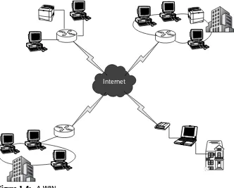
A WAN comprises multiple LANs and spans a large geographical distance. The most commonly known (and used) WAN is the Internet. Figure 1-4 shows an example of a WAN.
A network device known as a routeris used to connect LANs to the WAN. The router is used to collect the address destinations of LAN and WAN devices, and it uses these addresses to deliver data between devices.
Media Access Control Addressing
Every device on a LAN contains a physical address, called the Media Access Control (MAC) address. The MAC address is a unique hardware address that identifies each device on the network. Most Layer 2 protocols use the MAC address to identify a device on the network. Mac addresses are written in hexa-decimal notation, which is written in the base-16 numbering system.
Not all networking protocols will use the MAC address, but on broadcast networks, the MAC address allows all of the devices in the network to be iden-tified and allows delivery of frames intended for a specific destination. MAC addresses are permanently attached to a device and are assigned by product manufacturers.
Figure 1-4: A WAN
Typically, MAC addresses are read as a group and are divided into six sets of two hexadecimal digits. Each set is separated from the remaining sets by either a colon (:) or a hyphen (-). Figure 1-5 shows an example of how MAC addressing may appear.
Internet Protocol Addressing
An IP addressis a unique number that is used by devices to communicate with each other over a WAN. An IP address is much like a telephone number or a street address. An IP address is assigned to each host interface within a network. To communicate with any other device on a WAN, the sending and receiving device’s IP address must be known. An IP address may be static, which means that it is permanently assigned to a device. It can also be dynamically assigned
by a server that is within the LAN of the device.
IP addresses are broken into four octets. Each octet contains 8 bits. The octets are written in dotted-decimal notation. Dotted-decimal notation is simply a method of writing octet strings in the base-10 numeral system. Each octet is separated from the other octets with a decimal point. Figure 1-6 shows an example of binary to dotted-decimal conversion.
Figure 1-5: An example of a MAC address
Figure 1-6: An example of binary to dotted-decimal conversion 11010010 00001100 10000000 00100000
210.12.128.21
210 12 128 32
23-4F-AD-21-33-AF
IP Address Classes
IP addresses are broken down into different classes. This allows for the assign-ment of different classes to meet the needs of networks that have different sizes. IP addresses can be divided into two parts: One part identifies the net-work that the IP address is assigned to, and the other part identifies the device that has been assigned a particular IP address.
Table 1-1 shows how IP addresses are divided into classes. IP addressing is broken down into the following five classes:
■■ Class A (for networks that have more than 65,536 hosts)
■■ Class B (for networks that have between 256 and 65,536 hosts)
■■ Class C (for networks that have less than 256 hosts)
■■ Class D (reserved for multicasting)
■■ Class E (reserved for future use)
Class A Addresses
Class A addresses are used for very large networks. There are only a small number of Class A addresses. The leading bit in a class A address is always a 0. The next 7 bits identify the network, and the last 24 bits belong to the device in which the IP address is assigned.
Table 1-2 shows a breakdown of the octets in a Class A address.
Table 1-1: Dividing Sections of the IP Address for Each Class
IP ADDRESS CLASS NETWORK PORTION HOST PORTION
Class A Octet 1 Octets 2, 3, 4
Class B Octets 1, 2 Octets 3, 4
Class C Octets 1, 2, 3 Octet 4
Table 1-2: The Breakdown of the Octets in a Class A Address
FIRST BIT OCTET 1 OCTET 2 OCTET 3 OCTET 4
Class B Addresses
A Class B address is assigned to medium-size networks. The first bit is always a 1 and the second bit is always a 0. The remaining 14 leading bits of the address are assigned to the network, and the last 16 bits identify the device in which the IP address is assigned.
Table 1-3 shows a breakdown of the octets in a Class B address.
Class C Addresses
Class C addresses are the most common type of addresses and are assigned to thousands of networks throughout the world. The first and second bit of an IP address is a one (1) , with the third bit always being a zero (0). The remaining 21 leading bits identify the network number, and the last 8 bits are used to identify the device that the address is assigned to.
Table 1-4 shows a breakdown of the octets in a Class C address.
Class D Addresses
Class D addresses are reserved for multicast addresses and can range from 224.0.0.0 to 239.255.255.255. The class D address identifies a group of hosts in a network that are members of a multicast group. Multicasting allows for the delivery of information to multiple devices within a group. It is a very efficient strategy to deliver messages that need to be shared with all members of the group.
Table 1-5 shows examples of well-known Class D addresses.
Table 1-3: The Breakdown of the Octets in a Class B Address
FIRST BIT SECOND BIT OCTET 1 OCTET 2 OCTET 3 OCTET 4
1 0 Network ID Network ID Host ID Host ID
Table 1-4: The Breakdown of the Octets in a Class C Address
FIRST SECOND THIRD OCTET 1 OCTET 2 OCTET 3 OCTET 4
BIT BIT BIT
Table 1-5: Examples of Well-Known Class D Addresses
CLASS D ADDRESS DESCRIPTION
224.0.0.0 Reserved
224.0.0.1 All devices within a network segment 224.0.0.2 All routers within a network segment 224.0.0.9 Used to send routing information in a RIP
environment
Protocols and Other Standards
In data communication, a protocolis a convention that enables the establish-ment of a connection between networking devices. The protocol sets the rules by which the connection is established and the rules governing the transfer of data between the devices. A protocol can govern hardware, software, and sometimes both hardware and software.
Atechnical standard can be considered a guideline or an example of a specifi-cation. A standard is used to form a basis in which a technology or a protocol can be developed.
This section describes some of the more common protocols and technical standards.
Internet Protocol
The Internet Protocol (IP), as mentioned earlier in this chapter, is a data protocol that is used by a source and a destination to communicate across a network.
In an IP network, data is transferred in blocks known as packets. The IP makes no guarantees that the information that is contained within a packet is not damaged. It is possible for data to be damaged, sometimes duplicated, and sometimes dropped completely. This is known as best-effort delivery.
In a data network, a packetis the block of information that contains the data that is being transmitted between devices. A packet comprises the following three elements:
■■ Header:Contains instructions about the data that is contained in the
payload portion of the packet.
■■ Payload:Contains the data that is being transmitted.
■■ Footer:Contains end-of-packet information, as well as error-checking.
Figure 1-7: The IP packet header
As shown in Figure 1-7, the bits in the IP packet header are as follows:
■■ Version:Identifies the version number of the packet.
■■ Internet Header Length (IHL):This field identifies the length of the IP
packet header.
■■ Type of Service (TOS):Identifies the type of service. Used by networks to
identify the data being transported and helps determine how the packet is to be handled.
■■ Identification:Helps identify packet fragments to ensure they are kept
separate from other packet fragments.
■■ Flags:Keeps information as to whether or not fragmentation is used
and if there are more fragments.
■■ Fragment Offset:Directs the reassembly of packets.
■■ Time to Live (TTL):A timer that is used to keep track of a packet.
■■ Protocol:Identifies the next encapsulated protocol.
■■ Header Checksum:The checksum data of the IP header and the Options
field.
■■ Source IP address:Identifies the IP address of the source device.
■■ Destination IP address:Identifies the IP address of the destination.
■■ Options and Padding:Special instruction data for the packet and may
contain filler data to ensure that the data starts on a 32-bit boundary.
Interior Gateway Protocol
The Interior Gateway Protocol (IGP)is a protocol that is used to exchange routing information between devices within a single autonomous system. The infor-mation that is exchanged is then used by other network protocols to specify how data is transmitted to its destination.
0 1 2 3 4 5 6 7 8 9 10 11 12 13 14 15 16 17 18 19 20 21 22 23 24 25 26 27 28 29 30 31
Version IHL TOS Total Length
Identification Flags Fragment Offset
TTL Protocol Header Checksum
Source IP address Destination IP address
Exterior Gateway Protocol
The Exterior Gateway Protocol (EGP)is used to exchange data between multiple autonomous systems. Commonly used on the Internet, it allows communications between hosts to build routing information to ensure data can be transported from source to destination.
Routing Information Protocol
The Routing Information Protocol (RIP)is the most commonly used IGP in net-working today. RIP is used to manage information that is given to a router in a LAN (or group of LANs).
An edge device that supports RIP will send out RIP information to other edge devices. The information that each of these edge devices sends out is known as the routing table. The routing tablecontains information about all of the IP devices that the edge device knows about. Each of the neighboring devices then sends out routing information to its neighbors with the informa-tion that it has learned, along with the informainforma-tion of the devices that are local to it.
The route from one device to another is known as a hop. RIP determines the number of hops it takes to get from one device to another and uses that infor-mation to determine the distance it takes to get from one device to another.
RIP is a distance-vector routing protocol, which means that it makes routing decisions based on the distance between two communicating devices. It uses a routing table to make route decisions and it updates its routing table every 30 seconds. The routing table is reviewed each time a routing update occurs, and then it is recalculated with the best route to a destination IP address. Fig-ure 1-8 shows a diagram of a RIP header.
As shown in Figure 1-8, the bits in the RIP packet header are as follows:
■■ Command:This field describes the action of the message.
■■ Version:Identifies the RIP version being used.
■■ RIP Entry Table:This is a variable length and contains the routing table
information.
Figure 1-8: The RIP header
0 1 2 3 4 5 6 7 8 9 10 11 12 13 14 15 16 17 18 19 20 21 22 23 24 25 26 27 28 29 30 31
Command Version 0
Open Shortest Path First
The Open Shortest Path First (OSPF)protocol is another often used IGP. Larger autonomous systems might prefer OSPF to RIP because OSPF does not require the 30-second updates that RIP does.
OSPF is a link state, hierarchical routing protocol. This means that each device in the network calculates and maintains its own routing table, and updates occur only when a change in the network occurs.
OSPF can operate securely in a network. It authenticates peers before forming an adjacency with the peers. An OSPF network consists normally of several small networks, known as areas. A central area, known as the backbone area,
serves as the core of the OSPF network. All areas in an OSPF network must connect to the backbone. Figure 1-9 shows a diagram of an OSPF header.
As shown in Figure 1-9, the bits in the OSPF header are as follows:
■■ Version:Identifies the OSPF version.
■■ Type:Identifies the type of the request or reply that is contained in the
message.
■■ Length:Identifies the size of the header and the message.
■■ Router ID:Identifies the packets source.
■■ Area ID:Identifies the area that the packet belongs to.
■■ Checksum:Identifies the IP checksum of the packet, excluding the
authentication portion of the packet.
■■ Authentication Type:Identifies the procedure in which the packet is to be
authenticated.
■■ Authentication:For use by the type of authentication that was chosen
when forming the packet.
Figure 1-9: The OSPF header
0 1 2 3 4 5 6 7 8 9 10 11 12 13 14 15 16 17 18 19 20 21 22 23 24 25 26 27 28 29 30 31
Version Type Length
Router ID Area ID
Authentication Data
Virtual Router Redundancy Protocol
The Virtual Router Redundancy Protocol (VRRP)assists network reliability by allowing the advertisement of a virtual router as a default route for devices in a network. This virtual router is an abstract representation of a master VRRP router and a backup VRRP router. Two (or more) physical routers are config-ured to serve as a virtual router, with one being the master and one the backup. The master is the one that performs all routing functions at any one time. If the master router fails, then the backup router becomes the VRRP master.
VRRP message packets are transmitted encapsulated into IP packets. Fig-ure 1-10 shows a VRRP packet header.
As shown in Figure 1-10, the bits in the VRRP message header are as follows:
■■ Version:The VRRP version number.
■■ Type:The type of request or reply contained in the message.
■■ Virtual Router ID (VRID):This field identifies the router that the packet
is reporting a status for.
■■ Priority:Identifies the priority for the sending VRRP router.
■■ IP address count:Identifies the number of IP addresses that are
con-tained in the message.
■■ Authentication type:The authentication method that is used.
■■ Authentication interval:Defines the time interval (in seconds) that there
is between advertisements.
■■ Checksum:Identifies the bit count of the entire message.
■■ IP addresses:A list of all of the IP addresses that are associated with the
virtual router.
■■ Authentication data:Data used to authenticate the packet.
Digital Subscriber Line
The Digital Subscriber Line (DSL)technology is actually a group of technologies that allow for digital services over a copper telephone wire. DSL operates sim-ilarly to the way that the Integrated Services Digital Network (ISDN) operates, but at a much faster rate. The two most popular forms of DSL are the Asym-metric Digital Subscriber Line (ADSL) and the SymAsym-metrical Digital Subscriber Line (SDSL).
Asymmetric Digital Subscriber Line
Figure 1-10: The VRRP packet header
Symmetrical Digital Subscriber Line
Symmetrical Digital Subscriber Line(SDSL) transmits data at a higher rate than traditional modem technology does. The main difference between ADSL and SDSL is that SDSL transmits data at the same rate in both directions. An SDLS modem is required for the implementation of SDSL.
Integrated Services Digital Network
Integrated Services Digital Network (ISDN) is a standard for transmitting data over traditional telephone lines. ISDN supports faster rates of data transfer than traditional dial-up modem technology does. In ISDN, there are two types of data transmission channels: B-channels and D-channels. Additionally, there are two types of ISDN in use: Basic Rate Interface (BRI) and Primary Rate Interface (PRI).
Bearer-Channel
The Bearer-Channel (B-channel)is the main data channel in an ISDN connection. The B-channels carry all of the voice and data services within the ISDN con-nection. In ISDN, both the BRI and the PRI will have more than one B-channel configured for their ISDN services.
Delta-Channel
The Delta-Channel (D-channel)is the channel in ISDN that carries the control and signaling information. In ISDN technology, only one D-channel is required with either a BRI or a PRI configuration
Basic Rate Interface
Basic Rate Interface (BRI)is an ISDN configuration that consists of two 64 kilo-bits per second (Kbps) B-channels and one 16 kilokilo-bits per second D-channel. The two B-channels are often joined together to support a total data rate of 128 Kbps. BRI is most often used by smaller networks, or for residential use. BRI is often referred to as 2B+D (two B-channels plus one D-channel) or 2B1D (two B-channels, one D-channel).
0 1 2 3 4 5 6 7 8 9 10 11 12 13 14 15 16 17 18 19 20 21 22 23 24 25 26 27 28 29 30 31
Version Type Priority IP address count
IP Addresses Authentication Data
VRID
Primary Rate Interface
Primary Rate Interface (PRI)is an ISDN configuration that, in North America and Japan, uses 23 B-channels and 1 D-channel. Most of the rest of the world uses 30 B-channels and 1 D-channel. In PRI, the D-channel also carries data at 64 Kbps. Most large networks use PRI as their ISDN standard configuration.
Lightweight Directory Access Protocol
The Lightweight Directory Access Protocol (LDAP)standard was developed as a simple way to access and search directories that are running over TCP/IP. An LDAP directory consists of entries that are nothing more than a collection of attributes that identify groups and individuals assigned to the groups. Each entry in an LDAP directory defines which attributes are optional, which ones are mandatory, and what type of information the LDAP directory stores. An LDAP directory is hierarchical in nature, defining geographic and/or organi-zational boundaries.
Remote Authentication Dial-In User Service
Remote Authentication Dial-In User Service (RADIUS)is a protocol that allows Remote Access Servers (RAS) to communicate with a core RADIUS server to authenticate and authorize access to remote users. RADIUS is a vehicle that allows companies to store authentication on a core, central server that all remote servers can utilize. It’s easy for the company to maintain because there is a central source in which access policies are established, as well as a single point to log network access activities.
Figure 1-11 shows the RADIUS header.
As shown in Figure 1-11, the bits in the IP packet header are as follows:
■■ Code: Identifies the type of RADIUS message.
■■ Identifier: Allows for the grouping of requests and replies.
■■ Length: Identifies the length of the packet.
■■ Authenticator: Partly used in the password-hiding algorithm, and it also
is used to authenticate replies from the server.
■■ Attributes: Identifies the authentication details for requests and
responses.
Figure 1-11: The RADIUS header
0 1 2 3 4 5 6 7 8 9 10 11 12 13 14 15 16 17 18 19 20 21 22 23 24 25 26 27 28 29 30 31
Identifier Length
Networking Hardware
Networking hardwareis defined as the hardware that is used to allow for com-munication on the network. This includes all of the computers, printers, inter-face cards, various peripherals, routers, switches, hubs, and various other devices that are needed to perform network data communication.
Random Access Memory
Random Access Memory (RAM)is a type of computer data storage. RAM is used to store active data for quick access during processing. Computers (including networking gear) use RAM to store program data and code during the execu-tion of an applicaexecu-tion. RAM is randomly accessed and most data can be retrieved from anywhere within the RAM module instantly. Figures 1-12 and 1-13 show examples of RAM.
Modem
The modem’s name comes from the two main services it provides. It modulates
an analog signal to encode digital information and then it demodulatesthe sig-nal by decoding the data. The modem takes the 1s and 0s (the bits and the bytes) and turns them into an audio signal that is transmitted from the modem through the telephone wire to another modem.
Figure 1-12: An example of a RAM module
Channel Service Unit/Data Service Unit
The Channel Service Unit/Data Service Unit (CSU/DSU) is an interface device that connects a router to a digital circuit. One of the primary functions of the CSU/DSU is to maintain signal timing between communication devices. The CSU/DSU is required to be used whenever a dedicated circuit is needed.
The CSU/DSU is a Layer 1 device (Physical layer in the OSI Reference Model). In addition to maintaining communication signaling, the CSU/DSU is capable of performing error checking as well.
Computer Workstations
All of the end user’s computers in the network are considered workstations. Most workstations contain a network interface card (NIC), software for network-ing, and cables. Some workstations have local storage, but often files are stored on a server and are not accessed or stored locally. Virtually any computer can be considered a workstation.
Servers
Aserveris one of the most important pieces of equipment in a network. It acts as a storage device, as well as controlling the flow of information in the net-work. A server is a computer that has a lot of RAM and ample storage space to meet the needs of the LAN it supports. For example, a file server may perform many tasks at a time, so it must be fast enough and large enough to handle and control the data that it supplies. Following are some examples of types of servers:
■■ Internet server: Provides Internet application services, such as email
ser-vices and Web serser-vices.
■■ Email server: Provides storage services for emails and also provides
con-nections for users to access their email.
■■ File server: Provides file sharing services.
■■ Print server: Provides shared access to network printers.
Network Interface Cards
The network interface card (NIC) is what supplies the physical connection between a workstation and the network. Most NICs are integrated or built into the PC, although there are some that reside externally to the device that they support. The most popular types of NICs are Ethernet and Token Ring.
Switch
Aswitch provides a central location for multiple LANs to connect to the net-work. A switch is often called an intelligent hubbecause of its ability to sort data. Operating at the Data Link layer (Layer 2) of the OSI Reference Model, a switch can connect multiple network segments together at a central point.
When a switch receives a frame, it saves the MAC address of the originator and the port on which the frame was received. It will then use the data it col-lects to forward packets based on the MAC address. If it does not have the MAC address in its MAC address table, it will flood the frame out of all of its interfaces.
Figure 1-14 shows an example of using a switch to forward data in a LAN.
Figure 1-14: Example of a LAN for which a switch has been implemented to forward data Switch
Printer
Hub
Ahub(or concentrator) is used to connect multiple devices together in a central point. The hub operates at the Physical layer (Layer 1) of the OSI Reference Model. Unlike the switch, the hub is not intelligent enough to forward frames based on a MAC address. Instead, it simply forwards data it receives out of all of its interfaces.
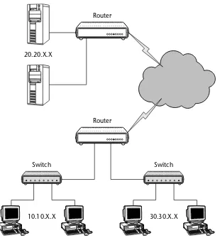
Router
Arouteroperates at the Network layer (Layer 3) of the OSI Reference Model and normally connects two LANs together, or a LAN to a WAN (see Figure 1-15). Routers use forwarding tables to determine what the best path is to a destina-tion. There are multiple routing protocols used by a router that assists in making the determination on where to forward data. Chapters 8 and 9 detail routing protocols in depth.
Most computers are capable of performing routing functions, but a router is a specialized computer that has extra hardware built in to speed up routing functions.
A router creates a routing table, which lists the best routes to any particular destination. The routing tables are built with information obtained through a routing protocol, such as the Routing Information Protocol (RIP). Chapter 8 includes additional information on RIP.
Repeater
Figure 1-15: An example of LAN-to-LAN and LAN-to-WAN networking via the router
Figure 1-16: A repeater used to boost the signal of data being transferred a long distance Repeater
Workstation Workstation
Switch Switch
20.20.X.X
Router
Router