1
SANTEN-fuse AS ANEARTHQUAKE DAMPER FOR
PENDOPO JOGLO
MAER, Bisatya W.1*, PUDJISURYADI, Pamuda2
1
Department of Architecture, Faculty of Civil Engineering and Planning, Petra Christian University, Jl. Siwalankerto 121-131, Surabaya 60236, INDONESIA
2
Department of Civil Engineering, Faculty of Civil Engineering and Planning, Petra Christian University Jl. Siwalankerto 121-131, Surabaya 60236, INDONESIA
*Corresponding author: [email protected]
ABSTRACT
The 2006 Yogyakarta earthquake resulted in collapse of several traditional buildings in Yogyakarta, including joglos. This fact indicates that joglos are quite vulnerable to low-frequency ground shaking. The stability and rigidity of a joglo building are provided by the core of the building, i.e. the rong-rongan structure, in which connection of sakaguru (the column)-sunduk (the long span beam)-kili (the short span beam) has a rigid characteristic. This rigid rong-rongan structure behaves elastically during an earthquake event, and attracts large inertia force. This research aims to increase the structure performance of the rong-ronganby adding “SANTEN-fuse,” an earthquake vibration damper, and by changing the joint connection of sakaguru-sunduk-kili to be that of a pin connection, but not changing the physical appearance of rong-rongan. Santen, whose function is to transfer the load of the roof from blandar to sunduk and from pangeret to kili, is modified so that it has frictional damper characteristic. This “SANTEN-fuse” can resist shear force up to certain level before it slides and acting as a damper. With the reduced stiffness, which leads to reduced inertia force, the overall structural responses are expected to be lower. An experimental quantitative method was used by doing a simulation using SAP2000 software to verify the idea. The pendopo dalem Yudonegaran a joglo house in Yogyakarta was chosen as a case study. Non-linear time history analysis was conducted. Simulation results showed that the proposed modification of rong-rongan structure by using
“SANTEN-fuse”, performed better than the original rong-rongan structure.
Keywords: Rong-rongan; SANTEN-fuse; non-linear time history analysis; structural responses.
INTRODUCTION
Pendopo joglo is one of the most valuable
traditional architectural masterpieces in Indonesia that needs to be conserved. Pendopo is an important part of a traditional Javanese home, and is located at the front part of the house. The pendopo functions as a space to socialize with family members, relatives, and even neighbors, actualizing a form of harmony between the house inhabitants and the local commu-nity (Hidayatun, 1999), while joglo refers to a parti-cular type of a traditional Javanese building.
The 2006 Yogyakarta earthquake resulted in the damage, even the destruction of some pendopo
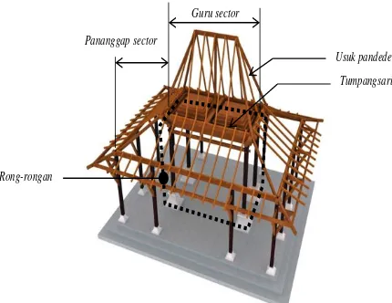
joglos. The pendopo joglo building consists of three
parts (Figure 1a), i.e. the guru sector that is located in the centre of the plan, the pananggap sector that is located around the guru sector, and the emper/
paningrat that is at theedge of pendopo surrounding
the pananggapsector (Prijotomo, 2005). Figures 1a
shows a pendopo joglo plan, while Figure 1b shows the section of sakaguru, Figure 1cillustrates the three dimensional model of the building. In the guru sector, there is an element called rong-rongan, which is made up of four sakagurus, two pair of blandars, a
pair of pangerets, a pair of sunduks, pair of kilis, and
santens. On top of the rong-rongan is the
tumpang-sari, which consists of a stack of beams arranged in a formation that gradually widens to the top, and above
the tumpangsari is usuk-usuk pandedel (Figure 1c,
2a). At the topmost part of rong-rongan there is
blandar on the long side (c) and pangeret on the short side (f), see Figure 2b. Under blandar there is sunduk
(b) and underneath pangeret there is kili (g). Between
blandar and sunduk, also between pangeret and kili, at some rong-rongan there is santen (d). Prijotomo (2005) argued that santen’s function is as a supple-ment, not in every rong-rongan there is santen. On
rong-rongan with wide length, santen is placed to forward the roof weight and tumpangsari from
blandar to sunduk/kili.The system of rong-rongan
structure can perform as Moment Resistant Frame (MRF) because its stability and rigidity are formed by locking joint between sunduk-sakaguru (b dan a) and
2
In a research titled “Perilaku rumah tradisional
Jawa joglo terhadap gempa”(“The performance of
Javanese joglo buildings toward earthquake”),
Prihatmaji (2007) proposed that joglo buildings were not stable in a low-frequency earthquakes, except when the support of sakaguru was changed into fixed support connection. The core structure that ensures the stability and rigidity of pendopo joglo is the
rong-rongan, which is located exactly in the centre of the
building plan. The structure of rong-rongan can perform as the MRF with a pin support connection because the joint connection between saka-sunduk
and saka-kili is a rigid joint. Inside of a few rong-rongan structures, there is an additional component, which is santen, whose function is to transfer the load of the roof from blandar to sunduk and from pangeret to kili.
In this research, the structural concept of the MRF is changed by modifying santen‟s function to be
the only lateral shear force support component as well as an earthquake vibration damper. The joints between saka-sunduk and saka-kili are changed to be pin joint connection, while the support of sakaguru
remains pin support connection. This new model of
santen with an altered function is labelled as
“SANTEN-fuse” by the researchers of the current study. The name was chosen to reflect the fact that the idea was sparked by the shape and construction of
santen. It is written in all capital to signify the different structural functions between SANTEN-fuse
and santen. Finally, the word „fuse‟ is commonly
used in the earthquake engineering field to illustrate a particular component that is used to dissipatethe energy of an earthquake, a process that is similar to how an electrical fuse cuts out an electrical current when there is an overload.
This research aims to investigate that the SANTEN-fuse can improve the performance of
rong-rongan during an earthquake eventcompared to the
original rong-rongan structure.
Joglo’s
GuruSector PananggapSect or
Emper
Figure 1a. Zonning in pendopo Joglo’s plan (Cited from Prijotomo, 2005)
c b
a a
Pananggap sector Pananggap sector
Guru sector
d
Rong-rongan
e e
Figure 1b. The Section of Pendopo Joglo (Do not include the Figure of Emper)
a = saka, b = sunduk, c = blandar, d= santen, e = tumpangsari
Tumpangsari
Rong-rongan
Pananggap sector
Guru sector
Usuk pandedel Pananggap sector
Source: http://achmad-jf.blogspot.com/2012/06/mengulas-sistem-struktur-joglo-dan-arti.html
Figure 1c. The Building Structure of Joglo (Excluding the Figure of Emper)
wedge
d
a
c
b
j
i
tumpangsari
f
d
c
g
h
A
B
C
Fig
Source: Frick, 1997
3
d m
d
a
c
b
j
i
f
d
c
a
g
h
A
B
C
a
c
b
f
g
d
e
Source: Frick, 1997
Figure 2b. Rong-rongan structure
a = saka, b = sunduk, c = blandar, d = santen, e = tumpangsari, f = pangeret, g = kili
f
d c
b a
g
h
A
B
C
ction Source: Frick, 1997
Figure 3. Connection construction detail of saka-sunduk-kili (a-b-g); saka-blandar-pangeret (a-c-f); santen-blandar-sunduk (d-c-b)
a = saka, b = sunduk, c = blandar, d = santen, f = kili, g = pangeret, h = dadapeksi)
f
d
c
a
g
h
A
B
C
Source: Ronald, 1987
Gambar 4. Structural model and moment diagram of rong-rongan.
THEORETICAL FRAMEWORK
Previously, the author has done a preliminary
research: “Bisakah struktur rong-rongan rumah joglo
hanya mengandalkan SANTEN?"(“Can rong-rongan
structure of joglo house only rely on SANTEN?”) (Maer, 2012). In this research, the model of
rong-rongan structure was modified to be a MRF Structure
in which the stability and the rigidity were only supported by SANTEN. In the modified rong-rongan
structure, the connections of saka-sunduk and saka-kili are pin joint connections. The previous research has proven that the modified structure model can stand with stability and has more or less the same rigidity as the original rong-rongan structure model (Maer, 2012).
In a different perspective, Dowrick (1977) offered a more economical solution, namely design-ing the structure in a way so as to perform the dissi-pation of the earthquake force through an inelastic behavior. When the structure receives a high mag-nitude earthquake force, some critical parts of the structural components performed the dissipation of energy (yielding), so that some of the earthquake force is released. But wood itself, which is commonly used in Joglo structures, is not ideal for this purpose (non ductile material)
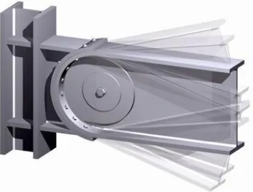
Wada (2004) recommended the usage of an additional tool or component in the structural ele-ments which are able to perform the energy dissi-pation without resulting in a permanent damage on the structural components, one of which is the Passive Energy Dissipation Control System (PEDCS). There are two PEDCS systems, which are: 1) damping which depends on friction (displacement), and 2) damping which depends on velocity. Pin-Fuse JointTM (Figure 5), patented by SOM (SOM Journal 4, p 69, 2004), is one example of PEDCS system usage with rotation friction damping.
Source:http://designbythebay.com/wp-content/uploads/2010/12/ Glamour_Shot.jpg
Figure 5. Pin-Fuse Joint TM
provided through translational sliding (friction damper). In order to test this proposed system, simulations were conducted by using the SAP2000 software. Ground acceleration consistent to Indone-sian earthquake response spectrum is used as the seismic load, and non-linear time history analysis were conducted. In the simulation, the performance of the experimental model of rong-rongan structure was compared to that of the performance of the original model of rong-rongan structure. The parameters used for comparisons were: the lateral deflections at the top of the rong-rongan, the shear force at sakaguru, the normal force at sakaguru, and the bending moment at
sakaguru.
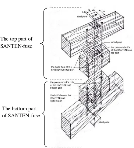
In developing the SANTEN-fuse, there are some considerations, as follows: 1) the overall the shape is kept relatively similar to the original santen; 2) the construction detail must be simple so that it is easy to build and repair; and 3) strong wood material should be used. With those considerations in mind, the shape and construction of SANTEN-fuse is proposed. The wood material should be class 2 or better (NI 5/PKKI 1978), and bolt specification according to type A325, with a dimension of 12 mm. SANTEN-fuse is divided in the middle of its height; the top part is connected to blandar/pangeret; the bottom part is connected to sunduk/kili. The dimension and propor-tion of SANTEN-fuse is designed to perform mainly on resisting shear and not on bending moment.
Blandar/pangeret, SANTEN-fuse, and sunduk/kili are
assembled using pressure bolt which is placed in exactly at center of SANTEN-fuse‟s axis line.The hole for the pressure bolt on the top part of the SANTEN-fuse is designed to be loose in order to allow for movement space for the bolt. However, the hole for the pressure bolt on the bottom part of the SANTEN-fuse is designed to fit the bolt's diameter (Figure 6a1, 6a2, 6a3), and Figure 6b show SANTEN-fuse in slip position when receiving lateral shear force.
nstr
The top part of bolt‟s hole dimension is 13 mm x 60 mm
Figure 6a1. The front elevation of SANTEN-fuse construc-tion
Figure 6a2. The plan of SANTEN-fuse construction
The top part of SANTEN-fuse
The bottom part of SANTEN-fuse
Figure 6a3. The perspektif of SANTEN-fuse construction
Figure 6b. SANTEN-fusein slip condition
This research is an experimental quantitative research with pendopo dalem Yudonegaran in Yogyakarta as the case study. This research is using
Ronald‟s (1987) research titled “Joglo building: A study of construction, proportion and structure of
royal houses in Yogyakarta” as a source for the case
study. Ronald (1987) studied several types of traditional Javanese buildings in Yogyakarta, one of which was the pendopo dalem Yudonegaran. The
pendopo dalem Yudonegaran was selected as a case
study in the present research because this particular
pendopo received the biggest bending moment at the
5 research, the performance between original model of
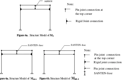
rong-rongan structure MA (Figure 6a) is compared
with two types experiment models of rong-rongan
structure MSF-1 dan MSF-2. MSF-1 is the original model
of rong-rongan structure with SANTEN-fuse added
(Figure 6b). MSF-2 is the modified model of
rong-rongan structure (the connections of saka-sunduk and
saka-kili are pin joint connections) with
SANTEN-fuse added (Figure 6c).
All three models of structure MA, MSF-1and M
SF-2 were analyzed using SAP2000 software. To each
model was given modified north-south El Centro earthquake acceleration input to produce acceleration response spectrum which consistent with Yogyakarta earthquake area in soft soils according SNI 2002. In those three models, rong-rongan is presumed supporting the whole seismic forces. The research consist 2 stages:
A. Comparing the performance of MA withMSF-1and MSF-2; and comparing the performance of MSF-1
with MSF-2.
B. Comparing the performance of MSF-2 + 1 pc
SANTEN-fuse, MSF-2 +2 pcs SANTEN-fuse, MSF-2 + 3 pcs SANTEN-fuse, and MSF-2 + 4 pcs
SANTEN-fuse.
Below are the variables which determine the damping level of the SANTEN-fuseon rong-rongan
structure:
Rigid zone, which positioned at the meeting point between the SANTEN-fuse with blandar/
pangeret and the SANTEN-fuse with sunduk/kili.
Inside this rigid zone, there is no alteration of angle between the SANTEN-fuse with blandar/
pangeret and the SANTEN-fuse with sunduk/kili.
The wide variable of rigid zone is set based on width to length ratio of the SANTEN-fuse(b/h) = 0.2, 0.5, and 1. Physically, rigid zone depends on SANTEN-fuse‟s dimension and construction section. The SANTEN-fuse‟s dimension is
determined based on: 1) the compressive strength of the wood towards the axial force of the pressure bolt; 2) the potential to perform rigid connecting behavior between SANTEN- fuse with blandar/ pangeret, and sunduk/kili; and 3) the ease in placing the bolt.
Friction coefficient (friction) at the interfaces of top-bottom of SANTEN-fuse. The friction coeffi-cient was setas much as 0.2, 0.4 and 0.6.
Axial compression force of SANTEN-fuse, which in turn depends on: 1) distributed load from the roof and tumpangsari on top of blandar; and 2) bolt tightening force (25%, 35%, 50%, and 75% of bolt allowable strength). If the roof structure and tumpangsari are set no resting on blandar, the axial compression force of the SANTEN-fuse comes only from bolt tightening force.
Maximum slip (cm) is the amount of maximum slip depends on the width of rigid zone. In this research the maximum slip is expected to be less than 5 cm.
Note:
santen
Rigid Joint connection Pin joint connection at the top corner
Figure 6a. Structure Model of MA
SANTEN-fuse SANTEN-fuse
SANTEN-fuse Note:
Pin joint connection at the top corner
Pin joint connection Rigid joint connection
THE OBSERVATION RESULTS AND MODEL SIMULATION STUDY
The analysis result of Diagram-1 and Diagram-2 showed that MSF-1 and MSF-2 perform better than MA,
however the performance development of MSF-2
towards MA is far more significant compared with the
performance development of MSF-1 towards MA. In
those two tables, all deflection values (d) of rong-rongan, shear force (V) of sakaguru, normal force (N)
of sakaguru and momen (M) of sakaguruwhich
happened to MSF-1 and MSF-2 is smaller than that
which happened to MA. Meanwhile, all of those
values on MSF-2 are smaller than on MSF-1. This result
shows that the performance of MSF-2 is the most
optimum compared with MSF-1 and MA.
The dissimilarity between the two performances was caused by the fixed rigidity of MSF-1 which came
from rigid joint connection between
sakaguru-sunduk-kili, while MSF-2 structure rigidity only
occurred because of the tightness of SANTEN-fuse (the -friction magnitude and axial force). When M
SF-1‟s SANTEN-fuse is tightened or loosened by increasing or decreasing the -friction and/or the axial force of SANTEN-fuse, the result of MSF-1 structure
rigidity is not significant compared to MSF-2 in the
same treatment. This resulted in the increase or decrease of the earthquake acceleration non linear time history response of MSF-1 to also be
not significant compared to MSF-2.
The next interest is whether the different number of SANTEN-fuse caused significant effect towards
MSF-2 performance. The analysis of the results is
summarized and simplified in Graphic-1 which shows the relationship between the magnitude of V slip of fuse and the maximum slip of SANTEN-fuse in MSF-2 with 1 piece, 2 pieces, 3 pieces and 4
pieces SANTEN-fuse. Graphic-2 shows the relation-ship between the magnitude of V slip of SANTEN-fuse and maximum deflection at the top of rong-ronganof MSF-2 with 1 piece, 2 pieces, 3 pieces and 4
pieces SANTEN-fuse.
Observed is categorized in three V slip group magnitudes, namely: 1000 kgf V slip, approximately 1400 – 1500 kgf V slip, and 6000 kgf V slip. These three groups show a trend of inconsistencies on the magnitude of the maxium slip of SANTEN-fuse and the maximum deflectionof MSF-2. It seems that this
phenomenon is the uniqueness of the non-linier structure: when MSF-2 is slipping, its condition
becomes non-linear. In that condition, when MSF-2
receives non-linear time history earthquake accele-ration, it is unclear whether it was the -friction, SANTEN-fuse axial force or the amount of
SANTEN-fuse which significantly resulted in maxi-mum slip, deflection at the top of rong-rongan, shear force on sakaguru, axial force on sakaguru and moment on sakaguru.
CONCLUSION
SANTEN-fuse addition can increase the perfor-mance of MSF-1 and MSF-2 structure models to be
better than original structure model MA. The addition
of SANTEN-fuse is more optimal if applied to rong-rongan structure with pin joint connection between
sakaguru-sunduk-kili that is similar to modified
rong-rongan structure (MSF-2) compared with rong-rongan
structure with rigid joint between sakaguru-sunduk kili that is similar to original rong-rongan structure (MSF-1). The number/amount of SANTEN-fuse is not
significant in determining the structure model MSF-2
result level.
RECOMMENDATIONS
The usage of SANTEN-fuse is recommended especially for modified rong-rongan structure where the connection between sakaguru-sunduk-kili uses pin joint connection. The addition of SANTEN-fuse can be applied to both the new pendopo joglo construc-tion and the existing pendopo joglo to improve its performance. However, special designed construction of SANTEN-fuse (SANTEN-fuse dimension, bolt dimension, tightness level of bolt) needs to be done for each pendopo joglo building and different earth-quake area.
The addition of SANTEN-fuse to existing
pendopo joglo without changing joint construction
between sakaguru-sunduk-kili can be done although the result will be less effective than if the construction joint between sakaguru-sunduk-kili is changed into pin joint.
Results from this study have shown that it is
possible to create an“earthquake friendly” structure in
joglo buldings. It is recommended that future research
in this field should focus on:
The effect of changing the structural function of
santen to SANTEN-fuse in relation to the archi-tectural meaning of pendopo Joglo.
Detailed construction design of joint between
sakaguru-sunduk-kili which is changed into pin
joint.
7 This research is developed based on secondary
literature data; therefore, there is a possibility that some of the experimental conditions may not reflect real-life situations. Thus, this also opens an opportunity for further field study.
the
Diagram 1. Maximum Deflection on the models: MA, MSF-1, MSF-2
Note:
The vertical axis = maximum deflection at the top of rong-rongan, in cm. The horizontal axis = the type of the models
ru (V
Diagram 2. Maximum Shear Force of Sakaguru (V saka), Axial Force of Sakaguru (N saka), and Moment of Sakaguru (M saka) on MA, MSF-1, MSF-2
Note:
The vertical axis = the magnitude of shear force (V, in kgf), axial force (N, in kgf), Moment M, in kgf m) of sakaguru
Graphic 1. Maksimum Slip of SANTEN-fuse vs V slip, for Friction = 0.4, On MSF-2 with 1 pcs., 2 pcs., 3 pcs., 4 pcs. SANTEN-fuse
Note:
The vertikal axis = maximum slip in cm
The horizontal axis = V slip in kgf; V 1000 = the magnitude of V slip = 1000 kgf, V 1463 = the magnitude of V slip = 1463 kgf,V 1500 = the magnitude of V slip = 1500 kgf,V 2400 = the magnitude of V slip = 2400kgf.
SANTEN-f1 = the amount of SANTEN-fuse is 1 pcs., SANTEN-f2 = the amount of SANTEN-fuse is 2 pcs., SANTEN-f3 = the amount of SANTEN-fuse is 3 pcs., SANTEN-f4 = the amount of SANTEN-fuse is 4 pcs.
Graphic 2. Maksimum Top Deflection vs V slip, for Friction = 0.4, On MSF-2 with 1 pcs, 2 pcs., 3 pcs., 4 pcs. SANTEN-fuse
Note:
The vertical axis = maximumtop deflection in cm The horizontal axis = V slip in kgf;V 1000 = the
magnitude of V slip = 1000 kgf, V 1463 = the magnitude of V slip = 1463 kgf, V 1500 = the magnitude of V slip = 1500 kgf, V 6000 = the magnitude of V slip = 6000 kgf.
REFERENCES
Arnold, C. and Reitherman, R. (1982). Building
configuration and seismic design. New York:
John Wiley & Sons.
Charleson, A. (2008). Seismic design for Architects,
Outwitting the quake. Amsterdam: Elsevier Ltd.
Dowrick, D.J. (1977). Earthquake resistant design, a
manual for engineers and architects. New York:
John Wiley & Sons.
Frick, H. (1997). Pola struktural dan teknik bangunan di Indonesia (“Structural patterns and building technique in Indonesia”). Penerbit Kanisius Hidayatun, M. I. (1999). Pendopo dalam era
moder-nisasi, bentuk fungsi dan makna pendopo pada
arsitektur tradisional jawa dalam perubahan
kebudayaan (“Pendopo in the era of
moderniza-tion, the shape function and meaning of the Javanese traditional pendopo architecture in culture change”). Journal Dimensi, 27(1), 37– 47.
Maer, B .W. (2012). Bisakah struktur rong-rongan rumah joglo hanya mengandalkan “SANTEN”?
(“Can Rong-rongan Structure of Joglo House Only Rely on SANTEN?”). National Confe-rence paper presented at The 45th Anniversary of
The Department of Architecture Petra Christian University, “Menuju arsitektur berempati” (“Towards theemphatic architecture”).
Prihatmaji, Y. P. (2007). Perilaku rumah tradisional
jawa Joglo terhadap gempa (The performance
of Javanese Joglo Buildings toward earthquake).
Jurnal Dimensi, 35(1), 1–12.
Prijotomo, J. (2005). Pengkonstruksian sektor guru dari griya Jawa: tafsir atas kawruh kalang
(Constructing the guru sector of griya Jawa: interpretations of kawruh kalang). Journal Dimensi, 33(2), 99–111.
Ronald, A., Santosa, M. and Soeleman. (1987). Joglo building a study of construction, proportion and
structure of royal houses in Yogyakarta.
Department of Architecture Engineering UGM. US Patent No 6,681,538 B1. (2004). Pin-Fuse
JointTM. SOM Journal, 4, 69.
Wada, A., Huang, Y. and Bertero, V. V. (2004). Innovative Strategies in Earthquake Enineering. In Bozorgnia, Yousef & Betero, Vitelmo V (Eds). Earthquake engineering, from engineer-ing seismology to performance-base enginerengineer-ing