Fuel Building
Nasruddin
1,a, M. Idrus Alhamid
1,b, Budihardjo
1,c, and Ratiko
2,d 1Department of Mechanical Engineering, Faculty of Engineering, Universitas Indonesia, Kampus UI Depok, Depok 16424, Indonesia
2
National Nuclear Energy Agency of Indonesia (BATAN), Tangerang 15314, Indonesia a
[email protected],[email protected], [email protected], [email protected]
Keywords: Indoor air quality; Contaminant dispersion; Interim storage for spent nuclear fuel
Abstract. The release of radioactive contaminants in nuclear facility within and around facility building could be caused by accident, faulty equipment, HEPA filter replacement or other causes. This can be harmful to the humans. This paper introduces potential contaminant dispersion analysis inside interim storage building for spent nuclear fuel in Serpong Indonesia. The simulation results show that the generation of radioactive contaminant in ISSF can be safely reduce by VAC system. The negative pressure design in ISSF can and avoid the spreading of contaminants into other rooms. However in VAC off condition, the contaminant concentration could exceed the maximum allowed limit. In the the existing building condition without VAC, there are relatively very small internal overpressure that can lead air and also harmful radioactive contaminant to flow out into ambient. However, if there are several leakages in building wall with different elevation, the risky overpressure phenomenon may be possible.
Introduction
In nuclear facility, the radioactive contaminants might be released within and around facility building. This contaminant dispersion can influence the indoor air quality and the occupant’s (worker) health and safety. Such events could be caused by accident, faulty equipment or HEPA filter replacement.
The investigated nuclear facility in this paper is the interim storage of spent nuclear fuel building, located in Serpong, Indonesia. The spent nuclear fuel, which put in storage, is spent nuclear fuel from nuclear research reactor in Serpong.
This paper introduces potential contaminant dispersion analysis inside interim storage building for spent nuclear fuel in Serpong Indonesia. In normal condition there are three radioactive gaseous contaminants, which could be released inside the interim storage building, i.e. Cs-137, I-131 and Xe-133. The contaminants dispersion scenario in this paper is on the conditions of HEPA filter replacement and ventilation system malfunction caused by an electricity failure or other causes.
Related Work
The studies on indoor air quality are more in non-nuclear facility building. Yu et al. tried to review the recent studies on indoor air quality control for human health [1]. Some researchers focused studies on indoor pollutants in solid (particle) [2] and gaseous phases [3]. The next shown group of topics in the study are control of contaminant sources [4], indoor air purification in form of: filtration [5], adsorption [6], photo catalytic oxidation [7], negative air ions [8] and non-thermal plasma [9].
damaged or accidental situations inside nuclear facilities buildings equipped with ventilation systems [15].
Building Description
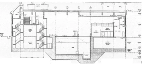
The interim storage for spent fuel (ISSF) building in Serpong consists of a storage pool area and office space area. The office area is a three floor building with an elevation of each of 5 meters. The storage pool area has a total height of 15 meters, which is equivalent to the height of three floors in an office area. Fig. 1 shows the side plan of the building.
Fig. 1. Interim storage for spent fuel in Serpong – Building side plan
To control and isolate the radioactive contaminants which might be released, the ISSF building in Serpong is equipped with supply and active extract ventilation system. To ensure the absence of radioactive contaminants from return air, the ventilation system consists of only supply air and exhaust air system. From air handling unit (AHU), the air is blown out through the air supply diffuser towards all conditioned rooms in the ISSF. The air is subsequently flowed through an exhaust fan to the HEPA filter bank (consisting of a pre-filter and HEPA filter) or to HEPA and charcoal filters bank. Before transferring to a filter bank, the air is passed to the radioactive detector. If radioactive contaminant is detected, the air is supplied to the HEPA and charcoal filter bank, if there is no radioactive contamination, the air is passed to the HEPA filter bank. Whole air coming out from the filter banks supplied to 30 meter high stack. There is no part of the air that is sent back to the AHU. In other words, the percentage amount of return air is 0% and the exhaust air is 100%.
Modelling Approach
There are 35-flow paths in the model. The flow paths are leakages form closed doorways and stairwells. Each storey/level is divided in several zones: 5 zones in basement, 10 zones in ground floor and 14 zones in first floor. From totally 29 zones, 12 zones are equipped with VAC system. As mentioned above, to ensure no spread of contaminants through contaminated return air, the return air is 100% blown into 30m-chimney through special HEPA and charcoal filter. Filter room and pool room, which have the potential to spread contaminant, are designed with 100±25 Pa negative pressure. The ambient temperature is 30°C and the room temperatur is 20°C.
The methematical models that can be used to correlate airflow and pressure difference is the power law model [16]. The general form of power law in volumetric flow form is:
Q = C (ΔP)n (1) In mass flow form is:
F = C (ΔP)n (2) which Q is volumetric flow in m3/s, F is mass flow in kg/s, C is flow coefficient in (m3/s)/Pan for volumetric flow and (kg/s)/Pan, n is flow exponent and ΔP is pressure difference in Pa.
The other model is one way flow using quadratic models [16]. The equations are:
ΔP = aQ + bQ2 (3)
where, the coefficient a is in Pa.s/m3 and b is in Pa.(s/m3)2
ΔP = aF + bF2 (4)
where, the coefficient a is in Pa.s/kg and b is in Pa.(s/kg)2
Results and Discussion
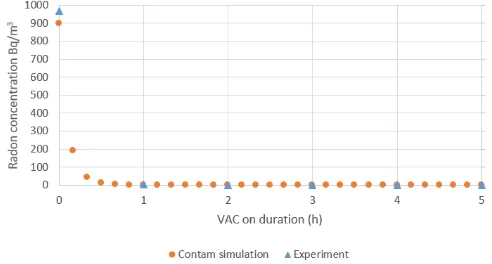
Prior to the simulation analysis in the ISSF, as validation, it would be investigated the congruence between experimental data value and the value from simulation. The data which to be compared are the contaminant concentration at radioactive waste treatment installation (RWTI) building after turning off and turning on the VAC system [17]. The RWTI building is located not too far away from ISSF.
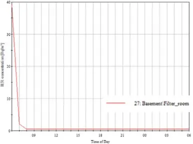
Fig. 3a shows tha the contaminant concentration values after stopping the VAC which obtained from simulation relatively close to the experiment values. Almost the same results are also retrieved on the decrease of radon concentration after reviving the VAC system, as shown in Fig. 3b. After 1 hour, the contaminant concentration falls to near zero.
Fig. 3a. The increase of contaminant concentration during VAC off – experiment and
simulation results
Fig. 3b. The decrease of contaminant concentration after turning on VAC – experiment and simulation
results
contaminant 131 is simulated to be spread at filter room in basement. Fig. 9 presents that the I-131 concentration after two hours period is at relatively constant value of 0.45 BQ/m3. The VAC system depress the contaminant concentration on the very low and safe value. The negative presure in filter room lead also, that the contaminant do not spread into other rooms. It is seen from Fig. 4a, that the contaminant concentration in Basement\Stairwell0a, Basement\Stairwell0b and Basement\Lift_0 are zero. The contaminant concentration in all other rooms in ground- and first floor from simulation result data are also zero.
Fig. 4a. Contaminant concentration for a release in the filter room at several rooms
Fig. 4b. Contaminant concentration for a release in the filter room in VAC off condition
In the VAC off condition, the contaminant concentration is increases linearly as shown in Fig. 4b. After 1 day, the concentration reaches up to nearly 40 Bq/m3. If the contaminant spread still generates, after 3 days the I-131 concentration could be exceed the concentration limit by Indonesian Nuclear Energy Regulatory Agency i.e. 100 Bq/m3 [18]. 12 days. Furthermore the concentration could be reached more than 450 Bq/m3, exceed the limit concentration in air by the Derived Air Concentration (DAC) of 416.67 Bq/m3 [19].
The VAC-turning off leads also the absence of negative pressure in filter room. With this condition, the spread of contaminant into other neighbor rooms is possible. The contaminant concentration in stairwell0a after 24 hour is 5.96E-05 Bq/m3. The contaminant spreads also into Near_stair0b (Basement), Stairwell1b (Ground floor) and Glass_room (Ground floor) in relatively small amounts. However, this small amounts of contaminant could be increase to a function of time. Similar to the case in RWTI building, by VAC reviving the contaminant concentration decrease rapidly in one hour VAC operation, and after two hour the concentration moves constant at a value of 0.45 Bq/m3. This can be seen in Fig. 5.
An important aspect in the VAC off period that needs to be investigated is the probability, that the contaminant flow out outside building through orifices. Fig. 6a shows that if there are leakages with different elevation in building wall, there is flow of air or contaminants from inside building into ambient. This is of course may be harmful. The contaminant concentration is than no longer rises linearly due the air flow out, as shown in Fig. 6b.
Fig. 6a. Flow and pressure difference due to leakages or orifices which have different elevation at VAC off
condition
Fig. 6b. Contaminant concentration for a release in the pool room in VAC off condition
and with leakages or orifices which have different elevation
The airflow without mechanical ventilation (VAC) can occur due the temperature and flow path elevation difference. This can be explained with the equations[20]:
The density change due to temperature.
ρ(T) = ρ(T0) [1 – β (T –T0)], with β = 1/273 (5)
CONTAM uses the following equation to calculate ρ[16]
ρ(T) = P0/(287.055 T) (6)
P1 = P0 – ρ . g. z1 (7)
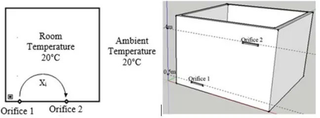
The case from Fig. 6b can be simplified with the case in Fig. 7a. The room temperature is 20°C, the air density is 1,204 kg/m3, the ambient temperature is 30°C, the air density is than 1,164 kg/m3, the elevation of orifice 1 is 0.5 m and 4 m for orifice 2.
Fig. 7a. Modeling of airflow from ambient to room through orifices Fig. 7b. CONTAM simulation for the case study
With the equations that have been written obove, it can be obteined the pressure difference at orifice 1 and orifice 2. Using mass conservation concept, F1 in kg/s = F2 in kg/s, it can then obtained the
airflow in orifice 1 ΔP1 = -0.682 Pa, it means the airflow in orifice 2 is from room to ambient or
Pamb1 < Proom1. The airflow in orifice 2 is ΔP2 = -0.682. It means Proom2 < Pamb2 or the airflow in
same values. The CONTAM simulation results show: The pressure difference in orifice 1 is 0.670 Pa with flow direction from room to ambient, and the pressure difference in orifice 2 is 0.693 Pa with the opposite direction.
Conclusion
The simulation results show that in normal condition, the generation of radioactive contaminant in ISSF can be safely overcome by VAC system. The sufficient air supply and the negative pressure maintain to reduce the existing contaminant and avoid the spreading of contaminants into other rooms.
In the case that there is contamination release and in VAC off condition, the contaminant concentration could exceed the maximum allowed limit. After VAC reviving, it need minimum 1-2 hour time until the contaminant concentration move in constant very low value.
In the VAC off condition with small leakages from all existing doorways in ISSF, there are relatively very small internal overpressure that can lead air and also radioactive contaminant to flow out into ambient. However, if there are several leakages in building wall with different elevation, the flow out of air and also radioactive contaminant in amounts which may be harmful may be happen.
References
[1] Yu, B., et al., Review of research on air-conditioning systems and indoor air quality control for human health. International journal of refrigeration, 2009. 32(1): p. 3-20
[2] See, S. and R. Balasubramanian, Risk assessment of exposure to indoor aerosols associated with Chinese cooking. Environmental research, 2006. 102(2): p. 197-204
[3] Huang, H. and F. Haghighat, Modelling of volatile organic compounds emission from dry building materials. Building and Environment, 2002. 37(12): p. 1349-1360
[4] Guo, H., F. Murray, and S. Lee, The development of low volatile organic compound emission house—a case study. Building and environment, 2003. 38(12): p. 1413-1422
[5] Hyttinen, M., P. Pasanen, and P. Kalliokoski, Removal of ozone on clean, dusty and sooty supply air filters. Atmospheric Environment, 2006. 40(2): p. 315-325
[6] Song, Y., et al., Toluene adsorption on various activated carbons with different pore structures.新型炭材料, 2005. 20(4): p. 294-297
[7] Zhao, J. and X. Yang, Photocatalytic oxidation for indoor air purification: a literature review. Building and Environment, 2003. 38(5): p. 645-654
[8] Sakoda, A., et al., A comparative study on the characteristics of radioactivities and negative air ions originating from the minerals in some radon hot springs. Applied radiation and isotopes, 2007. 65(1): p. 50-56
[9] Wang, C. and X. He, Effect of atmospheric pressure dielectric barrier discharge air plasma on electrode surface. Applied Surface Science, 2006. 253(2): p. 926-929
[10] Chauhan, N. and R.P. Chauhan, Active-passive measurements and CFD based modelling for indoor radon dispersion study. Journal of Environmental Radioactivity, 2015. 144(0): p. 57-61
[11] Chauhan, N., et al., Measurements and CFD modeling of indoor thoron distribution.
Atmospheric Environment, 2015. 105(0): p. 7-13
[12] Bulińska, A., Z. Popiołek, and Z. Buliński, Experimentally validated CFD analysis on sampling region determination of average indoor carbon dioxide concentration in occupied space. Building and Environment, 2014. 72(0): p. 319-331
GA and CFD. Building and Environment, 2007. 42(9): p. 3333-3340
[15] Le Roux, N., et al., Reduced-scale study of wind influence on mean airflows inside buildings equipped with ventilation systems. Building and Environment, 2012. 58: p. 231-244
[16] Walton, G.N. and W.S. Dols, CONTAM user guide and program documentation. 2005
[17] Budiyono, U., Gatot Sumartono. Influence of Vac Off Gas to Air Contamination in Radioactive Waste Instalation at PTLR Batan Serpong. 2013
[18] Agency, I.N.E.R., Decree of the head nuclear energy regulatory agency, nr: 02/Ka-BAPETEN/V-99, Radioactivity Limit in the Environment, I.N.E.R. Agency, Editor 1999 [19] Jiemwutthisak, P., et al., Air Monitoring to Control the Intake of Airborne Radioiodine-131
Contaminants by Nuclear Medicine Workers. 2012