EXTENDED MAPTREE: A REPRESENTATION OF FINE-GRAINED TOPOLOGY AND
SPATIAL HIERARCHY OF BIM
Yijie Wua,b, Jianga Shanga,b,∗, Xuke Huc, Zhiyong Zhoua,b
a
Faculty of Information Engineering, China University of Geosciences, 430074 Wuhan, China - (wuyijie, jgshang, zhouzhiyong)cug.edu.cn b
National Engineering Research Center for Geographic Information System, 430074 Wuhan, China
cGIScience Research Group, Institute of Geography, Heidelberg University, Heidelberg, Germany - [email protected]
Commission VI, WG VI/5
KEY WORDS:fine-grained topology, indoor spatial hierarchy, extended maptree, IFC
ABSTRACT:
Spatial queries play significant roles in exchanging Building Information Modeling (BIM) data and integrating BIM with indoor spatial information. However, topological operators implemented for BIM spatial queries are limited to qualitative relations (e.g. touching, intersecting). To overcome this limitation, we propose an extended maptree model to represent the fine-grained topology and spatial hierarchy of indoor spaces. The model is based on a maptree which consists of combinatorial maps and an adjacency tree. Topological relations (e.g., adjacency, incidence, and covering) derived from BIM are represented explicitly and formally by extended maptrees, which can facilitate the spatial queries of BIM. To construct an extended maptree, we first use a solid model represented by vertical extrusion and boundary representation to generate the isolated 3-cells of combinatorial maps. Then, the spatial relationships defined in IFC are used to sew them together. Furthermore, the incremental edges of extended maptrees are labeled as removed 2-cells. Based on this, we can merge adjacent 3-cells according to the spatial hierarchy of IFC.
1. INTRODUCTION
Building Information Modeling (BIM) provides abundant seman-tic information and multi-schema representations of 3D geometry for indoor entities. BIM facilitates the information exchange among stakeholders in AEC (Architecture, Construction and Engineering) Industry (Santos et al., 2017). The information demands of stakeholders vary with individuals and process phas-es, while the most of them should be extracted from the overall building model (Mazairac and Beetz, 2013). Spatial queries can be used in the information extraction by filtering spatial objects. Additionally, they can be used in the integration of BIM with indoor spatial information. This would benefit subsequent spatial analyses and improve the efficiency of data processing.
At present, the research (Gao et al., 2015, Lawrence et al., 2014, Mazairac and Beetz, 2013, YING and Lee, 2016) has been conducted to query BIM, but the research in the spatial queries of BIM is still in its infancy. The filter expressions of spatial queries can consist of metric, directional, and topological operators. In this paper, we only concentrate on the existing research in the topological aspect of spatial queries. Query Language for Building Information Model (QL4BIM) (Daum and Borrmann, 2014) provides topological operators which are implemented by using a boundary representation-based method. The algorithms of QL4BIM are proposed to determine qualitative relations in 9-Intersection Model.
Existing topological operators of BIM fail to directly support fine-grained or space-hierarchical topological queries. One ex-ample of this situation is determining which surfaces of two adjacent entities are sharing. The other example is finding out the common surfaces of a storey and its bounding exterior walls and slabs, which requires grouping entities in the spatial hierarchy. Several studies (Fradin et al., 2006, Hu and Lee, 2004) have been conducted to develop a fine-grained and space-hierarchical
∗Corresponding author
topology-based model for indoor spaces, but not specifically for BIM.
Based on the maptree proposed in (Worboys, 2012, Worboys, 2011), we propose a model namedExtended Maptreefor IFC-based BIM, consisting of combinatorial maps and an adjacency tree. An extended maptree is a fine-grained topological represen-tation organized by the spatial hierarchy of indoor spaces. Fine-grained adjacency and incidence are represented by combinato-rial maps while the spatial hierarchy of a building is mapped to an edge-labeled and node-colored tree. Incremental edges are introduced in original maptrees, which are labeled as the removal of darts in a combinatorial map. They are used to merge the adjacent elements on each spatial level. Additionally, the construction of combinatorial maps is customized for IFC due to its multi-schema representations of the geometry and characteristics derived from the spatial relationships defined explicitly. Spatial queries can be conducted on an extended maptree whose components have pointers to the entities of BIM. In this paper, we only design and implement the structure of an extended maptree for IFC and its construction approach. The implementation of the specific algorithms of queries on an extended maptree is still ongoing. Additionally, we focus on the construction of an extended maptree for the Manhattan layouts of indoor spaces (Coughlan and Yuille, 2003), which represents the vertical and horizontal indoor entities. To simplify the construction task, we utilize some open sourced functions that have been implemented in existing libraries to process combinatorial maps and parametric geometries.
2. PRELIMINARIES
fine-grained and unambiguous adjacency and inclusion between regions can be represented. Several definitions and concepts related to the two main components (combinatorial maps and adjacency tree) are given as follows.
2.1 Combinatorial Map
An n-dimensional combinatorial map, orn-map, is a topological model which is presented for the boundary representation of geometric modeling. Combinatorial maps use a single type of basic elements called dart to represent the subdivisions of topological spaces. An i-cell with i ∈ {0, . . . , n} is used to implicitly denote a vertex, an edges, a face, or a volume. Moreover, the adjacency and incidence relations of i-cells are modeled explicitly by links which are permutations in n-maps. More detailed definitions of combinatorial maps can be found in (Lienhardt, 1989, Lienhardt, 1994). We introduce some related notions as follows.
Definition 2.1: (n-map) An n-dimensional combinatorial map,
or n-map, with n ≥ 0, is defined as an (n+1)-tuple M = (D, β1, . . . , βn), such that:
1. Dis a finite set of darts;
2. β1is a permutation onD;
3. ∀i,2≤i≤n,βiis an involution onD;
4. ∀i, j,1≤i≤i+ 2≤j≤n,βiβj1is an involution onD.
In addition, aconnected componentof the map is also an n-mapM′which is incident to a dart of D. A connected n-map has only one connected component.
Definition 2.2: (orbit) LetD be a set of darts,α0, . . . , αnbe
permutations onD, anddbe a dart ofD. hα0, . . . , αnidenotes
the group of permutations which are defined as composition or inverse ofα0, . . . , αn. Anorbitofdrelated to these permutations
is denoted ashα0, . . . , αni(d).
Definition 2.3:(i-cell) LetM = (D, β1, . . . , βn)be an n-map,
and dbe a dart of D. For anyi, 0 ≤ i ≤ n, the i-cellCi
containingdis defined as:
1. C0=h{βiβj|∀i, j,1≤i < j≤n}i(d);
2. C1=hβ2, . . . , βni(d);
3. ∀i∈ {2, . . . , n−1}, Ci=hβ1, . . . , βi−1, βi+1, . . . , βni(d);
4. Cn=hβ1, . . . , βn−1i(d);
We name the n-cell of an n-map, which represents the open exterior space asn-map cell. Note that the notions of combina-torial maps in maptrees are developed for the context of spatial informatics. However, to directly use the data structures and operations of original combinatorial maps, we follow the original definitions of n-maps. The operations includesewingtwo n-cells,
insertingi-cells into j-cells (with0≤i < j≤n), andremoving
i-cells (with0 ≤ i ≤ n). They modify an n-map by updating the set of darts and linking or unlinking the darts inβi. We
use and extend these operations which have been implemented in CGAL (CGAL, 2017) to construct an extended maptree.
1β
iβjis the composition ofβiandβj, i.e.,∀d∈ D,βiβj(d) =
βi(βj(d))
2.2 Adjacency tree and maptree
We are incapable of distinguishing the inclusive and disjoint relations of the two connected components of an disconnected n-map, without additional geometric information (Worboys, 2012). Thus, adjacency trees, one of the main structures of maptrees, are gathered to guarantee an unambiguous representation in the above-mentioned case.
Definition 2.4: (adjacency tree) Given a disjoint set S of
closed curves embedded in a closed surface, such that the curves partition the surface into regions. An adjacency tree is defined asT = (N, E), whereNandEare the finite sets of nodes and edges, respectively. In addition, each node points to one region, while each edge joins two nodes whose regions share a common boundary.
In order to join n-maps with adjacency trees in a more direct way, all disconnect maps are separated into several connected n-maps to guarantee no inclusion in an n-map. Therefore, a maptree can provide a unique formal representation of an n-dimensional space by linking n-maps and their n-cells with the nodes and edges of an adjacency tree.
Definition 2.5: (maptree) LetMbe a finite set of connected
combinatorial maps. A maptree is defined as an edge-labeled and node-colored bw-treeTMwhose edges are labeled by the n-cells. To simplify subsequent descriptions, we name nodes associated with regions asregion nodesand nodes associated with n-maps
asn-map nodes.
3. AN EXTENDED MAPTREE OF IFC
3.1 IFC classes modeled in extended maptrees
Figure1 illustrates related IFC classes in this work. IfcBuilding,
IfcBuildingStorey, and IfcSpace are utilized to form the basic
spatial hierarchy, which are related to spatial structures. We only use the vertical and horizontal subtypes ofIfcBuildingElement. These subtypes can be used to generate the Manhattan-World layouts of spatial structures. We also utilize the classes related to spatial relationships (e.g. IfcRelSpaceBoundary) which are associated with two elements and connection geometry to con-struct an extended maptrees. Note that the schemas of geometric representations in IFC are restricted to boundary representation and vertical extrusion.
3.2 Spatial hierarchy and covering relations
Although spatial hierarchies can be derived from
IfcRelAggre-gateswhich represents the aggregation of
IfcSpatialStructureEle-ment, the exit sequences of space structures are utilized to derive the hierarchy in a more programmatic fashion. More specially, the lower level of the hierarchy a spatial structure is on, the more exits a pedestrian should go through to reach the spatial structure. For instance, a storey is on a higher level of the hierarchy than its rooms since the exit sequence of the storey is shorter than the exit sequences of the rooms. Thus, an exit sequence-based spatial hierarchy can be treated as a tree whose nodes represent spatial structures and edges represent exits. A spatial structure associated with a node can be directly reached through the exit associated with the preceding edge of the node.
!"#$%&'%(#&)*"&*)+,(+-+.&
!":%"+&+0/)+$ !"#;+$&<)+%#2('0 !",=&)*0+0<)+%#2('0
!"#(%5#&%.0%)07%8+
Figure 1. The UML diagram of the related IFC classes in this paper
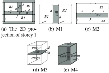
the spatial structure. However, maptrees have limitations in representing the indoor spatial hierarchy with covering relations. As illustrated in Figure2, an original maptree does not group R1, R2 and W5 to Z1. We can resolve this issue by using the extended maptree of IFC.
Figure 2. Covering relation represented by the original maptree
3.3 Labels and colors assignments for spatial hierarchy
An original maptree is a generic model for fine-grained and formal topological representations. We extend the original map-tree, considering the characteristics of configurations in indoor environment. More specially, we propose several new colors and labels which will be assigned to nodes and edges, respectively. We use the length of exit sequences to distinguish indoor spatial objects on the different levels of the hierarchy. We define that if a spatial structure(i.e., the instances ofIfcSpatialStructureElement) can be reached by going throughiexits then the spatial structure
isi-reachable, otherwisei-unreachable. We assume that each
spatial structure has at least one exit and a minimum length of exit sequencesiminto reach the spatial structure. In order to
guarantee this assumption, virtual exits should be introduced by separating the real exits or by appending new ones. In the case that a room exit is both a building entrance and a storey exit, this exit should be separated into three single exits for the building, storey and room, respectively. In this case, theiminof the room
equals three. The other case is that a spatial structure is bounded by virtual boundaries (i.e., the instances ofIfcVirtualElement). Virtual exits should be attached to the virtual boundaries. To overcome the limitations of maptrees in representing the indoor spatial hierarchy with covering relations, we introduce
incremental edgeswhich are labeled as the removal of 2-cells.
An incremental edge is used to merge adjacent 3-cells. The successive node of an incremental edge is an n-map node. 2-cells inside the associated n-map should be removed and be the labels of the incremental edge. Moreover, the preceding node of an incremental edge is a region node whose 3-cell is generated by merging 3-cells. Furthermore, an instance ofIfcBuildingElement
whose 2-cells are removed, subdivides a spatial structure on a
higher level of the hierarchy into two adjacent spatial structures. The exit sequences of these two adjacent spatial structures are coincident except for the last exits.
!
Figure 3. An extended maptree example of Figure 4
R1 R2 jection of storey 1
R1
Figure 4. The 3-cells and combinatorial maps of Figure 3
New assignments of 4 colors of nodes and 5 kinds of labels of edges are defined as follows.
Black Node: A black node is an n-map node whose n-map is a
connected combinatorial map. The associated n-map of a black node can be a connected local part of a connected n-map.
White Node:A white node is a region node which is associated
with a spatial structure (e.g., the instances of
IfcSpatialStruc-tureElement). The associated spatial structure does not directly
Gray Node: A gray node is a region node which is associated with an instance of IfcBuildingElement. Gray nodes are leaf nodes.
Red Node:A red node is a region node which is associated with
a spatial structure (e.g., the instances of IfcSpatialStructureEle-ment). The associated spatial structure covers spatial structures and building elements in the lower level of spatial hierarchy. A red node is the parent node of a black node.
RB Edge: A RB edge is an incremental edge which links a
preceding red node and a successive black node. It is labeled as the removed 2-cells in the associated n-map of its successive black node.
BW Edge:A BW edge is an edge which links a preceding black
node and a successive white node. It is labeled as a two-tuple
L = (3 −cell, imin) where 3−cell represents the spatial
structure of its successive white node andiminis the minimum
number of exits to reach it.
WB Edge:A WB edge is an edge which links a preceding white
node and a successive black node. It is labeled as the n-map cell of its successive black node. The associated spatial structure of its preceding white node contains all the regions of its successive black node.
BR Edge: A BR edge is an edge which links a preceding black
node and a successive red node. It is labeled as a two-tuple
L= (3−cell, i)where3−cellrepresents the spatial structure
of its successive red node. idenotes an exit number, which is one less than that of the child white nodes or red nodes of the successive black node.
BG Edge: A BG edge is an edge which links a preceding
black node and a successive gray node. It is labeled as a 3-cell representing the building element of its successive gray node. An example of the extended maptree is given in Figure 3. The corresponding configurations and the 3-maps of the building modeled are shown in Figure 4.
4. CONSTRUCTION APPROACH
The first step of the construction is creating isolated 3-cells from the solid models of IFC. Then, we sew adjacent cells along 2-cells according to the spatial relationships defined in IFC. Finally, the 2-cells of building elements are removed according to the spatial hierarchy, which is followed by assigning node colors and edge labels. Existing libraries including IfcOpenShell (IfcOpenShell, 2017), Open Cascade (or OCCT) (OCCT, 2017), and CGAL (C-GAL, 2017) are used in the construction.
4.1 Creating isolated 3-cells from Solid Models
This step concentrates on vertical extrusion which is a kind of the parametric modeling of geometry and boundary representation. More specifically, the solid models we use are the instances of
IfcFacetedBrep and IfcExtrudedAreaSolid. Since
combinatori-al maps are topologiccombinatori-al models, used for modeling boundary representation (Lienhardt, 1991), the inputting solid models would be decomposed into simpler geometric objects of different dimensions (i.e., points, curves and surfaces). Exiting libraries have implemented this procedure, such as IfcOpenShell which is an open sourced project of processing IFC data. Functions in IfcOpenShell convert the instances of IfcSolidModel into topological data structures (namedTopoDS) defined in OCCT. In addition, the instances of 3D TopoDS are composed of vertices, edges and faces. The components of different dimensions in 3D TopoDS can be explored by functions in OCCT. Note that we only create isolated 3-cells for building elements and
spatial structures without covering or containing any other spatial structures or building elements in this step. Thus, the 3-cells of spatial structures such as the instances of IfcBuildingand
IfcBuildingStoreyare generated in Section 4.3.
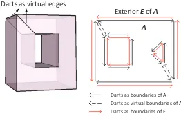
A 2-cell with holes can result in ambiguousness in a 3D maptree. In order to distinguish holes and disjoint 2-cells, virtual edges are inserted into a 2-cell with holes for linking its external boundary and inner boundaries, as illustrated in Figure 5.
!
Figure 5. Darts as the virtual boundaries of 2-cells with holes
Figure 6 illustrates the procedure of creating isolated 3-cells from the instances of TopoDS. For each instance of TopoDS, all the faces and their boundaries (including an external boundary and 0, 1, or more internal boundaries) are obtained. One dart is created for each edge of the boundaries when we generate a 2-cell for a face. Moreover, we assume that the solids of IFC modeled by TopoDS are close, so each edge is shared by two adjacent faces and two darts should be created for each edge. Two 2-cells are regarded as adjacent along an edge only if one 2-cell contains one of the two darts of the edge while the other 2-cell contains the other one. Thus, after creating a dart for an edge, the approach would check the existence of a second dart of the edge. If so, the two darts are glued as an adjacent 2-cell. Then, the approach differentiates an internal boundary and an external boundary. The last step is linking a newly created dart to a previous dart because the edges of the boundary are obtained in an edge-connecting order.
Figure 6. Create isolated 3-cells from TopoDS
4.2 Sewing 3-cells via Spatial Relationships
Isolated 3-cells created from the solid models in the previous step should be ”sewed” according to their adjacency relations. Al-though the adjacency relationships can be derived by calculating the intersection of solid models or detecting common boundaries with tolerance values, this procedure is still quite complex and may causes conflicts with spatial relationships represented by
IfcRelationship. Therefore, we propose some simple criteria to
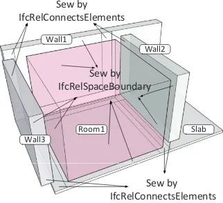
sew the isolated 3-cells according to spatial relationships defined in IFC. As illustrated in Figure 7, the solid models ofIfcWall,
IfcSlabandIfcSpacecan be sewedIfcRelConnectsElementsand
!""#
Figure 7. Sew 3-cells by IFC relationships
4.2.1 Attaching geometric attributes
In order to sew the isolated 3-cells along the correct 2-cells, some geometric attributes should be attached to cells or darts. The attached attributes should be concise but enough to make each 2-cells of the 3-cells distinguishable because the 2-cells are used to sew 3-cells.
An isolated 3-cell has a pointer to the instance ofIfcFacetedBrep
or IfcExtrudedAreaSolid. If it is created from the instance of
IfcFacetedBrep, each 2-cell of the 3-cell has a pointer to the
instance of IfcFace. The instances of IfcFace constitute an instance ofIfcFacetedBrep. The values of the extrusive direction and depth of an extrusive solid can be obtained from an instance of IfcExtrudedAreaSolid if a 3-cell is created from the extrusive solid. However, the parameters cannot be mapped to the 2-cells directly. Thus, we map the 2-cells to the corresponding prism of an extrusive solid. The 2-cells of the bottom faces of an extrusive solid are marked as FROM and TO. The one marked as FROM is associated with the profile of an extrusive solid. The other 2-cells marked as SIDE are associated with the side faces of an extrusive solid.
4.2.2 Sewing with connection geometry
Connection geometry is defined in the instances of
IfcRelSpace-BoundaryandIfcRelConnectsElements. 2-cells which two 3-cells
are adjacent along can be determined by connection geometry. Figure 8 illustrates the three categories of mapping from the connection geometry to a 2-cell. Two adjacent solids are located in the first row while the corresponding 2-cell of the solidC2is located in the second row. A common face can be mapped to the whole, the partial or the internal 2-cell of an original 2-cell. In the case of partial cell, one or more1-cell are inserted into a 2-cell, splitting the original 2-cell into two new 2-cells. In the case of internal 2-cell, a sequence of 1-cells is inserted into a 2-cell, splitting the 2-cell into an internal and an external 2-cell. Note that virtual edges should also be inserted in order to connect the external boundary and inner boundaries of a 2-cell with holes. The details of sewing 3-cells by IfcRelConnectsElements and
IfcRelSpaceBoundaryare discussed as follows.
The instances of IfcRelConnectsElements represent adjacency relations between the two instances ofIfcBuildingElementwhose geometric representations are limited to the instances of
IfcEx-trudedAreaSolid. The solid ofIfcBuildingElementsuch as
IfcWall-StandardCaseis extruded vertically and the two walls are
adja-cent along their side faces. Therefore, the connection geometry given by an instance ofIfcRelConnectsElementsis a curve which is on the external boundary of the profile of an extrusive solid.
!
Figure 8. Mapping categories from the connection geometry to a 2-cell
Figure 9 illustrates the procedure of sewing two 3-cells by a connection curve. The first step is determining the segments of the boundary of an extrusive profile, which overlaps or intersects with a connection curve. The next step is determining the SIDE 2-cells whose external boundaries share the segments. Next, the procedure determines whether to split the 2-cell vertically. If the curve does not cover the overall segment, the 2-cell should be split into two or three 2-cells.
!"#$%&"$'()*"$'!*")$%&"$
Figure 9. Sew 3-cells by a connection curve
The instances of IfcRelSpaceBoundaryrepresent adjacency re-lations between an instance of IfcSpace and its bounding in-stances ofIfcBuildingElement. For simplicity, we only consider the adjacency relations among IfcSpace, IfcWallStandardCase,
IfcSlabStandardCase, andIfcVirtualElement. IfcVirtualElement
is used to bound open spaces in a same storey. Similar to the procedure of sewing 3-cells by using a connection curve, the initial 2-cells along which two 3-cells are sewed are determined first. Then, we can derive the final 2-cells along which two 3-cells are sewed by inserting 0-3-cells, 1-3-cells and splitting 2-3-cells, as illustrated in the Figure 10. The simplest cases is that the overall interior of a face is overlapped by a connection surface, and the darts of the 2-cell can be thus directly sewed. Otherwise, an initial 2-cell should be split according to the intersection of its associated face and the connection surface. Thus, we implement the splitting step by inserting a dangle sequence of 1-cells into the 2-cell first and then sew the 1-cell of the dangle end with the corresponding 1-cell.
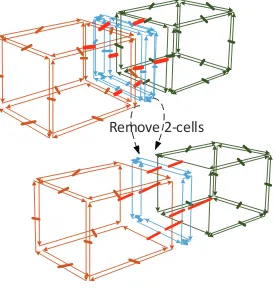
4.3 Removing 2-cells and constructing an extended maptree
Connected 3-maps can be created from an IFC model by the above-mentioned steps. In this section, we remove the 2-cells of building elements (Figure 11) and label incremental edges according to the semantical attributes of 3-cells. The 3-cells created by the previous steps have pointers to the instances
of IfcSpatialStructureElement or IfcElement. Moreover, exit
sequences are also the semantic attributes of 3-cells created from
IfcSpatialStructureElement. In order to combine an extended
!"#$%&'$ ()%*&!"+$,)*'$
)"#$-.*'// 0"%'12'*%!3"$3,$
241,)*'$)"#$,)*'
546632'$"4(7'1$3,$ '#+'2$!"2!#'$%&'$,)*'$!2$"
8".-9$:.*'//2
;;; ;;;
8".:9$:.*'//2 0"2'1%$3"'$
#)"+/'$'#+' <!"=$>'1%!*'2
0"2'1%$>'1%'?
0"2'1%$" #)"+/' $'#+'2
0"2'1%$>'1%'?@ <!"=$>'1%!*'2 0"2'1%$"
>'1%!*'2
Figure 10. Sew 3-cells by connection surface
introduce a bitset (i.e., a set to store bits) as an attribute of a dart. The bitset is denoted asMarkand is used to store the level of the spatial hierarchy. The size of aMarkequals to the maximum length of exit sequences. Each bit positionM ark[i]uses boolean variable to indicate whether the dart is represented on theith
spatial level. The spatial structures on theithspatial level are
i-reachable. IfM ark[i]is false, then the dart is omitted in theith
spatial level. Each position of theM arkof a dart is initialized as true while it could be updated as false when constructing an extended maptree.
!"#$!%&'(!))*
Figure 11. Remove 2-cells to merge adjacent 3-cells
Algorithm 1 implements the key step of merging adjacent 3-cells in a same spatial level. The idea of this algorithm is inspired by the seed filling algorithm which can be used to process adjacent pixels in images. The inputs of the algorithm includes a 3-cell which is the first seed of the procedure. The last but one exit of the exit sequence of the 3-cell is denoted asExit. Exitis the other input of the algorithm. The first step is to find out all the 3-cells that are adjacent to the seed 3-cell (line 1→3). If the length of the exits sequences of a candidate 3-cell and the seed 3-cell are equal and they have same previous exits, the Mark value of each dart of the 2-cells shared by the two 3-cells is set as false (line 4→7). Next, the functionRemove 2cells of bldgElemis called to remove 2-cells and merge 3-cells (line 8). At last, we call the functionSeedMergingfor processing the adjacent 3-cells of the seed 3-cell (line 9).
An extended maptree can be constructed according to Algorithm 2 in a recursive fashion. An exit is the input of the algorithm, which is denoted as Exit. One spatial structure denoted as S can be directly reached byExit. IfS does not have other exits through which the spatial structures on a lower level of the hierarchy can be reached, the recursive algorithm reaches its base case (line 2→3). The function SeedMerging is called to merge the adjacent 3-cells ofS(line 7). If the recursive function does
Algorithm 1:(SeedMerging)Merging spatial structures
Input: A 3-cell of spatial structure 3Cell seedas a seed 3-cell
to merge adjacent spatial structures, the previous exit Exitbefore the exit to reach the 3Cell seed
Output: A 3-cell 3Cellmerged from 3Cell seed
1 if 3Cellis not processed in the level ofExitDepththen
2 set 3Cellasprocessed;
3 foreach 3-cell 3Cell itof the adjacent spatial structures
of 3Cell seeddo
4 ifthe exit sequences of 3Cell itand 3Cell seedare
of the same lengththen
5 ifthe previous exit of the 3Cell itis the same with
Exitthen
6 foreach dartDart itof the 2-cells which are
the common boundary of building elements and
space structuresdo
7 Dart it.mark[the length of the exit
sequence of 3Cell seed] = 0;
8 3Cell←
REMOVE2CELLS OF BLDGELEM(3Cell it,
3Cell seed);
9 SEEDMERGING(3Cell it,Exit);
10 return 3Cell;
not reach its base case, it continues calling itself with the next exit as the input (line 4→6). Note that a spatial structure on a lower spatial level thanScan be reached by a next exit.
Algorithm 2:(TreeCons)Constructing an extended maptree
Input: The exitExitand its depthDepth
Output: a 3-cell 3Cellmerging the 3-cells of the spatial
structures whose exit sequence containsExitwith the length larger thanDepth
1 Initialize 3Cell tempas null;
2 ifthere is no next exit ofExitthen
3 3Cell temp←the 3-cell of the spatial structure can be
directly reached byExit;
4 else
5 foreach next exitExit itofExitdo
6 3Cell temp←TREECONS(Exit it,Depth+ 1)
7 3Cell←SEEDMERGING( 3Cell temp,Exit);
8 return 3Cell;
5. CONCLUSION AND FUTURE WORK
In this paper, an extended maptree is proposed for representing fine-grained topology and spatial hierarchy based on exit se-quences. An incremental edge labeled as the removal of 2-cells is introduced. Several new label and color assignments are used to distinguish the semantical types of 3-cells in combinatorial maps for indoor space. Additionally, the construction approach of an extended maptree of IFC is proposed. The approach includes three steps: creating isolated 3-cells, sewing 3-cells via spatial relationships and removing 2-cells to generate a final extended maptree.
and inconsistency between spatial relationships and geometric representations. Second, the implementation of spatial queries algorithms on the extended maptrees of IFC is still ongoing. Third, the extended maptree and corresponding construction approach are limited to the representation of the Manhattan World layouts of indoor spaces. Our future work would popularize the model and its constructing approach, enabling the representation of the curved and inclined indoor spatial objects of IFC.
REFERENCES
CGAL, 2017. CGAL: The Computational Geometry Algorithms Library. http://www.cgal.org.
Coughlan, J. M. and Yuille, A. L., 2003. Manhattan world: Orientation and outlier detection by bayesian inference. Neural
Comput.15(5), pp. 1063–1088.
Daum, S. and Borrmann, A., 2014. Processing of topological bim queries using boundary representation based methods.Advanced
Engineering Informatics28(4), pp. 272–286.
Egenhofer, M. J. and Franzosa, R. D., 1991. Point-set topological spatial relations. International Journal of Geographical
Information System5(2), pp. 161–174.
Fradin, D., Meneveaux, D. and Lienhardt, P., 2006. A hierarchical topology-based model for handling complex indoor scenes. In:Computer Graphics Forum, Vol. 25number 2, Wiley Online Library, pp. 149–162.
Gao, G., Liu, Y.-S., Wang, M., Gu, M. and Yong, J.-H., 2015. A query expansion method for retrieving online bim resources based on industry foundation classes.Automation in construction
56, pp. 14–25.
Hu, H. and Lee, D.-L., 2004. Semantic location modeling for location navigation in mobile environment. In: Mobile Data Management, 2004. Proceedings. 2004 IEEE International
Conference on, IEEE, pp. 52–61.
IfcOpenShell, 2017. IfcOpenShell: an open source (LGPL) software library that helps users and software developers to work with the IFC file format. http://ifcopenshell.org.
Lawrence, M., Pottinger, R., Staub-French, S. and Nepal, M. P., 2014. Creating flexible mappings between building information models and cost information. Automation in Construction45, pp. 107–118.
Lienhardt, P., 1989. Subdivisions of dimensional spaces and n-dimensional generalized maps. In:Proceedings of the fifth annual
symposium on Computational geometry, ACM, pp. 228–236.
Lienhardt, P., 1991. Topological models for boundary representation: a comparison with n-dimensional generalized maps.Computer-aided design23(1), pp. 59–82.
Lienhardt, P., 1994. N-dimensional generalized combinatorial maps and cellular quasi-manifolds. International Journal of
Computational Geometry & Applications4(03), pp. 275–324.
Mazairac, W. and Beetz, J., 2013. Bimql–an open query language for building information models. Advanced Engineering
Informatics27(4), pp. 444–456.
OCCT, 2017. Open CASCADE Technology (OCCT). http-s://www.opencascade.com.
Santos, R., Costa, A. A. and Grilo, A., 2017. Bibliometric analysis and review of building information modelling literature published between 2005 and 2015.Automation in Construction.
Worboys, M., 2011. Modeling indoor space.
Worboys, M., 2012. The maptree: A fine-grained formal representation of space. In: International Conference on
Geographic Information Science, pp. 298–310.
YING, H. and Lee, S., 2016. Comparative analysis of the applicability of bim query languages for energy analysis. In:CIB