SMARTPHONES BASED MOBILE MAPPING SYSTEMS
A. Al-Hamad*,and N. El-Sheimy
Department of Geomatics Engineering, Schulich School of Engineering, University of Calgary, 2500 University Dr. NW , Calgary, Alberta, Canada T2N 1N4 - (amr.al-hamad, elsheimy)@ucalgary.ca
Commission V, ICWG I/Va
KEY WORDS: Closed Range Photogrammetry, Mobile Mapping System, Smartphones, MEMS, Epipolar Geometry, Bundle Adjustment.
ABSTRACT:
The past 20 years have witnessed an explosive growth in the demand for geo-spatial data. This demand has numerous sources and takes many forms; however, the net effect is an ever-increasing thirst for data that is more accurate, has higher density, is produced more rapidly, and is acquired less expensively. For mapping and Geographic Information Systems (GIS) projects, this has been achieved through the major development of Mobile Mapping Systems (MMS). MMS integrate various navigation and remote sensing technologies which allow mapping from moving platforms (e.g. cars, airplanes, boats, etc.) to obtain the 3D coordinates of the points of interest. Such systems obtain accuracies that are suitable for all but the most demanding mapping and engineering applications. However, this accuracy doesn’t come cheaply. As a consequence of the platform and navigation and mapping technologies used, even an “inexpensive” system costs well over 200,000 USD. Today's mobile phones are getting ever more sophisticated. Phone makers are determined to reduce the gap between computers and mobile phones. Smartphones, in addition to becoming status symbols, are increasingly being equipped with extended Global Positioning System (GPS) capabilities, Micro Electro Mechanical System (MEMS) inertial sensors, extremely powerful computing power and very high resolution cameras. Using all of these components, smartphones have the potential to replace the traditional land MMS and portable GPS/GIS equipment. This paper introduces an innovative application of smartphones as a very low cost portable MMS for mapping and GIS applications.
* Corresponding author.
1. INTRODUCTION
The main motivation of using any MMS is its ability to provide accurate, fast and economic mapping solution. This solution increases the efficiency of spatial data collection for different GIS applications such as mapping of roads, railways, utilities and infrastructures. However, the major drawback of current MMS is their high price due to the type of the used platform, navigation and mapping technologies. Even an “inexpensive” system costs well over $200,000. Because of their high cost, the market for such land-based MMS is rather small, and such systems are typically “one-off” systems that are operated by the companies or institutions that build them. In effect, this means that while several companies are making a profit using MMS, few are making a profit manufacturing them. This also means that the benefits of mobile mapping – in particular the lower costs and greater efficiency of data collection – are not being enjoyed (Ellum and El-Sheimy, 2002a).
Today’s smartphones enable normal users around the world to make voice and video calls, send messages and e-mails, capture images and many other applications. eMarketer estimates there are 1.75 billion smartphone users in 2014 around the world which means that there is an approximately one in every five people in the world owns a smartphone (eMarkter, 2014). Nowadays, most of the smartphones contain both accelerometers and gyroscopes which are required for different applications and games. Yole development estimates there are 497M units of smartphones with accelerometers and gyroscopes (Yole Development, 2012).
One of the most important features of smartphones is their ability to determine the location of their users using low cost GPS receiver and different motion sensors. Smartphones are considered the most widespread platform that equipped with a low cost GPS receiver, which can provide the position of the user within few meters accuracy in Line of Site (LOS) environments, and indoor using low cost MEMS based Inertial Measurement Unit (IMU) which contains three accelerometers and three gyroscopes. In addition, recent smartphones also include three magnetometers, one barometer and high resolution digital cameras. The potential of these sensors, which are required for mobile mapping, in one platform motivates researchers around the world to develop new algorithms and applications for mobile phones outside the traditional voice calls, SMS etc. As an example, low cost MEMS based motion sensors have played a crucial role in developing low cost commercial navigation applications for indoor and poor-GPS environments for pedestrian navigation.
The main challenge, however, of using smartphones for mapping applications is their sensors’ errors which deteriorate the accuracy of the obtained position and orientation solutions of the smartphones. In photogrammetry, these parameters are called Exterior Orientation Parameters (EOPs). These erroneous EOPs can’t be used for different mapping applications without absolute update source
In this paper, the obtained matched images from the phone are used as an update source to remove the accumulated errors of the obtained EOPs from the IMU and GPS receiver. Using a set of matched points between images and the epipolar geometry
constraints, a new proposed method is implemented to refine the erroneous initial EOPs. Using the new solved EOPs, captured images can be directly georeferenced and bundle adjustment software can be used to calculate the 3D coordinates of the interest points.
This paper proposes a new very low cost mobile mapping system with reasonable accuracy using the existing motion, navigation, and imaging sensors in smartphones. Different photogrammetric principles will be used in the proposed system. In this paper, promising results clearly show that smartphones will indeed be a major source for geospatial data in the near future.
The rest of this paper has been organized as follows: The development history of MMS is reviewed in section 2. Section 3 gives a summary of the georeferencing aspects of the proposed MMS system. Section 4 explains the used methodology to use smartphones as MMS. Results and analysis are shown in section 5. Section 6 gives a summary and concludes this paper.
2. DEVELOPMENT OF MMS
The development of the MMS has been accomplished through different steps (Tao, 2000). Photo logging systems were firstly used to monitor roads for maintenance purposes (pavements, signs, etc.). However, photo logging systems did not have the ability to calculate the 3D object coordinates. Mobile mapping technology has witnessed a rapid development during the past 20 years. MMS composed of two main types of sensors; navigation and imaging (mapping) sensors (Ellum & El-Sheimy, 2002a). Navigation sensors, such as IMUs and GPS receivers, are used to determine the position and the orientation of the mapping sensors. On the other hand, passive imaging sensors such as digital cameras or active imaging sensors such as laser scanners can be used as mapping sensors. In addition to the 3D mapping capabilities, MMS offers the ability to directly georeference their mapping sensors which means knowing their EOPs at exposure times without the need for any control points.
The final solution of MMS can be accomplished by several steps (Tao, 2000). After data acquisition of the georeferenced images and spatial information, information extraction and management can be done. To determine the 3D coordinate of any object of interest, at least two conjugate images are needed for this object. Objects of interest can be edges, surfaces, roads centrelines, traffic signs, etc. More images for the same object mean more accurate solution. Information extraction can be done using different automatic extraction techniques (Kingston, et al., 2007).
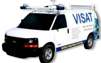
One of the first operational land-based MMS is the VISAT system which has been developed by the department of Geomatics engineering at University of Calgary. In the VISAT system, a 0.3 meter absolute position accuracy and 0.1 meter relative accuracy has been obtained using a dual frequency carrier phase differential GPS, eight digital cameras and a navigation grade IMU which has been used to improve the accuracy of the mapping solution during GPS signal outages. The main objective for the VISAT project was to develop an accurate MMS for road and GIS data acquisition at the normal highway vehicle speed (e.g. 100 km/hr.) (Schwarz, et al., 1993).
Figure 1. VISAT System
In general, the assessment of any mobile mapping system is performed using different factors such as accuracy, cost, portability, power consumption and others. Accuracy and cost are the most important factors for any assessment. The final accuracy of the system is a function of the complete processing chain which involves GPS positions, INS position/attitude, target localization in the images, and system calibration. More information about the accuracy assessment of the mapping systems can be found in (El-Sheimy, 1996).
Another MMS example is the backpack mobile mapping system has been developed by Ellum and El-Sheimy to obtain a low cost and complexity, small size and accurate MMS without using any ground control points (Ellum and El-Sheimy, 2002b). In addition to a Novatel GPS receiver, the authors used the Leica digital compass and Kodak consumer digital camera. Several software has been used in order to complete this work. The obtained relative accuracy was about 5 cm while the absolute accuracy was 0.2m in horizontal direction and 0.3m in vertical direction. In (El-Hakim, et al., 1997) a mobile mapping system has been developed for indoor 3D mapping and positioning where 8 CCD cameras, dead reckoning system and a range sensor have been used for this purpose. For road mapping and features localization applications, many mapping systems have been developed in the last two decades, some examples can be found in (Artese, 2007), (Gontran, et al., 2007), (Ishikawa, et al., 2006), (Ishikawa, et al., 2007) and (Piras, et al., 2008).
In addition to the high cost of all current MMS, time synchronization between the different sensors of the MMS is another challenge. Using smartphone as a mobile mapping platform, both; the cost and the synchronization problems can be solved since all the required components for mapping are integrated in one platform where a common clock can be used to synchronize all the data without any additional setup.
3. GEOREFERNCING ASPECTS OF THE SYSTEM
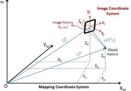
Georeferencing video images can be defined as the problem of transforming the 3-D coordinate vector the image frame to the mapping frame (m-frame) in which the results are required. Using the GPS and IMU measurements to compute the position and the rotation of the smartphone in mapping frame, the 3D coordinates of interest points can be calculated using equation (1) (See Figure 2).
I P M I M SP M
P
r
R
r
r
(1)
Where
r
PMandr
SPMare the object point and smartphoneposition vectors in the mapping frame,
r
PIis the position vectorof point p in the image frame (I), and I M
R are the scale factor and the rotation matrix between the mapping and the image coordinate systems. The lever arm between the image plane and smartphone is ignored since it is small compared to the error in the GPS receiver measurements of the smartphone.
The relationship between image and mapping (ground) coordinate systems is usually described using the collinearity equations where the image point, object point and the perspective centre of the camera are collinear. Figure 2 shows the coordinate systems used in this research work; smartphone and mapping coordinate systems.
Figure 2. Mapping and Smartphone coordinate systems
As can be noticed from Figure 2, both vectors fA and fa are
X = perspective centre ground coordinates.
A A A Y Z
X , , = object point ground coordinates.
Another important aspect that should be considered in the georeferencing is the camera calibration parameters. For many medium accuracy applications, computing the first radial distortion coefficient (k1) is usually sufficient. Both the higher radial distortion coefficients and the decentric distortion parameters can be ignored. More information about camera calibration can be found in (Fraser, C.S., 1997). . After substituting equations (3) and (4) in (2) and dividing the result by the focal length c, we could obtain the two extended collinearity equations (5) and (6) which include the effect of the radial distortion. the x and y directions of the image. Using two or more images and collinearity equations, the 3D coordinates of interest points in mapping frame can be calculated as shown in Figure 3.
Figure 3. Direct Georeferencing
4. PROPOSED METHOD
4.1 The Used Device
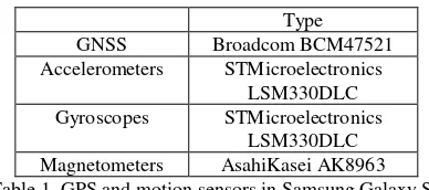
In this research work, Samsung Galaxy S4 smartphone has been used as the MMS platform. The Samsung Galaxy S4 contains a high resolution 13 MP digital camera and accurate motion sensors. The types of the Global Navigation Satellite System (GNSS) receiver and different motion sensors inside S4 smartphone are listed in Table 1. The axes definitions of S4 device is shown in Figure 4.
Figure 4. Samsung S4 axes definitions
Type
GNSS Broadcom BCM47521
Accelerometers STMicroelectronics LSM330DLC Gyroscopes STMicroelectronics
LSM330DLC Magnetometers AsahiKasei AK8963 Table 1. GPS and motion sensors in Samsung Galaxy S4
4.2 Initial EOPs and IOPs Values
Bundle adjustment is a non-linear least square estimation where initial values for the unknown vector are very important to obtain a converged solution. Bad initial values may lead to a divergence of the final solution. In this research work, ideal IOPs parameters values are used as initials values. On the other hand, the measurements of the GPS, accelerometers and magnetometers are used to initialize the EOPs of each image. Latitude, longitude and height measurements of the GPS receiver are used to compute the initial values of the camera shifts in the north, east and up directions between each two consecutive images as shown in equations (7), (8) and (9).
)
= the latitude, longitude and height GPS measurements.earth
R = the radius of the earth at a given latitude.
The initial rotation values of the smartphone at exposure times can be calculated using the measurements of the accelerometers and magnetometers as shown in equations (10), (11) and (12) where roll and pitch angles are the rotation angles around the y and x axes of the smartphone and Azimuth is the deviation angle of the leveled smartphone from the north direction.
)
magx, magy= magnetometers measurements.
4.3 EOPs and IOPs Correction
Without knowing the scale factor between the image and the ground coordinate systems, a point in any image can be any epipolar lines intersect at the epipole.
Figure 5. Epipolar Geometry
Using MEMS based IMU and low cost GPS receiver inside smartphones, good initial values for the EOPs of each image can be obtained as discussed in section 4.2. However, these initial values are not accurate enough to be used as an input for the bundle adjustment mapping software. In this paper, a new novel method has been used to correct the initial values for the IOPs and EOPs of the images. Figure 6 shows the used method which uses a set of matched points only for correction. In the image below, xI and xI’ are two image matched points for the same object. c1 and c2 are the perspective centres of the camera in the two images. In the left image, the object point for the equation of this epipolar line is shown in equation (13).
1
Using a set of matched points and the initial values of the IOPs and EOPs, the true EOPs and IOPs can be calculated using non-linear least square estimation technique where the distance d is used as a cost function.
Figure 6. EOPs Correction
4.4 Mapping Solution
Using the corrected IOPs and EOPs values from the previous step, bundle adjustment software is used to estimate the 3D ground coordinates solution of the points of interest in the mapping frame (ENU frame). In this bundle adjustment software, the observation vector is the difference between the measured image matched points and the expected ones using the extended collinearity equations shown in equations (5) and (6).
5. RESULTS AND ANALYSIS
To test the proposed method, six images have been captured for a test field at University of Calgary with known positions target points. The positions of these images are shown in Figure 7 and the images themselves are shown in Figure 8.
Figure 7. Locations of the taken images (Google Earth)
Figure 8. The taken six images.
Figures 9 and 10 show the image plane in the proposed method using initial EOPs values obtained in section 4.2 and the corrected ones after using method in section 4.3. As can be seen from these figures, the matched points do not belong to their corresponding epipolar lines using the initial EOPs values calculated from the GPS receiver and motion sensors of the smartphone. After correcting the EOPs values, the distances between the matched points and their corresponding epipolar lines are approximately equal to zero as shown in Figure 10.
Figure 9. Image plane using initial EOPs
Figure 10. Image plane using correcetd EOPs
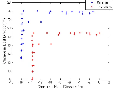
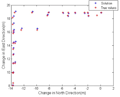
After obtaining the corrected EOPs, they are used for mapping using the UofC bundle adjustment software. Mapping results without using any control points are shown in Figure 10. This mapping solution has a very good relative accuracy. However, mapping solution without using any control points is shifted and scaled due to the errors in the GPS receiver measurements. In addition, this mapping solution might be rotated as well due to the error in the Azimuth angle of the first reference image. Using two control points to shift, scale and rotate the final solution, more accurate absolute results can be obtained as shown in Figure 11. As can be noticed from Table 2, the maximum 3D error is approximately 38 cm while its standard deviation does not exceed 10 cm. Also, results in the north direction are better due to the good geometry of the captured images in that direction as shown in Figure 7. More accurate results can be obtained using more images with better geometry.
Figure 11. Mapping solution without using any control points
Figure 12. Mapping solution using two control points
North East Up 3D Maximum Error (m) 0.204 0.240 0.268 0.376 Standard Deviation(m) 0.055 0.072 0.081 0.092 Table 2. Maximum errors and its standard deviations
6. CONCLUSION
In this paper, smartphones are used as MMS to overcome the problem of the high cost and time synchronization of the traditional MMS. The main problem of using smartphones as MMS is the poor accuracy of their sensors and GPS. To solve this problem, a new method has been proposed. Promising results have been shown in this paper which shows that smartphones will indeed be a major source for GIS data in the future.
ACKNOWLEDGEMENTS
This work was supported in part by research funds from TECTERRA Commercialization and Research Centre, the Canada Research Chairs Program, and the Natural Science and Engineering Research Council of Canada (NSERC).
REFERENCES
Artese, G., 2007. ORTHOROAD: A low cost Mobile Mapping System for road mapping. In: C. V. Tao & J. Li, eds. Advances in Mobile Mapping Technology - ISPRS Book Series. London: Taylor & Francis, pp. 31-41.
El-Hakim, S. et al., Sept. 1997. A Mobile System For Indoors 3-D Mapping And Positioning. Zurich, Optical 3-D Measurement Techniques.
Ellum, C. and El-Sheimy, N. 2002a. Land-Based Mobile Mapping Systems. ASPRS.
Ellum, C. and El-Sheimy, N., 2002b, Portable Mobile Mapping Systems, the US Institute of Navigation, 2002 National Technical Meeting, January 28-30, 2002 - San Diego, California ION NTM paper.
El-Sheimy, N., 1996. A Mobile Multi-Sensor System For GIS Applications In Urban Centers, The International Society for Photogrammetry and Remote Sensing (ISPRS) 1996, Commission II, Working Group 1, Vol. XXXI, Part B2, pp.
95-100, Vienna, Austria, July 9-19, 1996, Best Young Authors Award Winning Paper.
eMarkter, 2014. Article in eMarkter newsletter
http://www.emarketer.com/Article/Smartphone-Users-Worldwide-Will-Total-175-Billion-2014/1010536.
Fraser, C. S., 1997. Digital Camera Self Calibration. ISPRS Journal of Photogrammetry & Remote Sensing, Volume 52, pp. 149-159.Gontran, H., Skaloud, J. & Gilliéron, P.-Y., 2007. A mobile mapping system for road data capture via a single camera. In: C. V. Tao & J. Li, eds. Advances in Mobile Mapping Technology - ISPRS Book Series. London: Taylor & Francis, pp. 43-49.
Ishikawa, K., Amano, Y., Hashizume, T. & Takiguchi, J.-i., 2007. A Study of Precise Road Feature Localization using Mobile Mapping System. Zurich, IEEE.
Ishikawa, K., Takiguchi, J.-i., Amano, Y. & Hashizume, T., 2006. A Mobile Mapping System for road data capture based on 3D road model. Munich, Germany, IEEE.
Kingston, T., Gikas, V., Laflamme, C. & Larouche, C., 2007.
An Integrated Mobile Mapping System For Data Acquisiotion And Automated Asset Extraction. Padua, Italy, The 5th International Symposium on Mobile Mapping Technology MMT '07.
Piras, M., Cina, A. & Lingua, A., 2008. Low cost mobile mapping systems: an Italian Experience. Monterey, CA, IEEE.
Schwarz, K. et al., 1993. VISAT - A Mobile Highway Survey System. Ottawa, IEEE - IEE Vehicle Navigation & Information Systems Conference.
Tao, C., 2000. Mobile Mapping Technology for Road Network Data Acquisition. Journal of Geospatial Engineering, Volume Vol. 2, No.2, pp. 1-13.
Yole Development (2012)μ “MEMS Markets & Applications- Market report”