A1.1 Introduction
Structures are devices for conducting forces from the points where they originate in buildings to foundations where they are ultimately resisted. They contain force systems which are in a state of static equilibrium. An appreciation of the concepts of force,
equilibrium and the elementary properties of force systems is therefore fundamental to the understanding of structures.
A1.2 Force vectors and resultants
Force is a vector quantity which means that both its magnitude and its direction must be specified in order to describe it fully. It can be represented graphically by a line, called a vector, which is drawn parallel to its direction and whose length is proportional to its
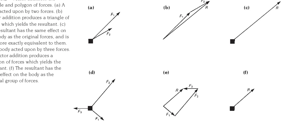
magnitude (Fig. A1.1). When two or more non-parallel forces act together, their combined effect is equivalent to that of a single force which is called the resultant of the original forces. The magnitude and direction of the resultant can be found graphically by vector addition in a ‘triangle of forces’ or a ‘polygon of forces’ (Fig. A1.2). In this type of addition the resultant is always represented, in both magnitude and direction, by the line which is required to close the ‘triangle of forces’ or ‘polygon of forces’.
128
Simple two-dimensional
force systems and static
equilibrium
Fig. A1.1 Force is a vector quantity and can be represented by a line whose length is proportional to its direction and whose direction is parallel to its direction.
Fig. A1.2 Vector addition: the triangle and polygon of forces. (a) A body acted upon by two forces. (b) Vector addition produces a triangle of forces which yields the resultant. (c) The resultant has the same effect on the body as the original forces, and is therefore exactly equivalent to them. (d) A body acted upon by three forces. (e) Vector addition produces a polygon of forces which yields the resultant. (f) The resultant has the same effect on the body as the original group of forces.
(a) (b) (c)
A1.3 Resolution of a force into
components
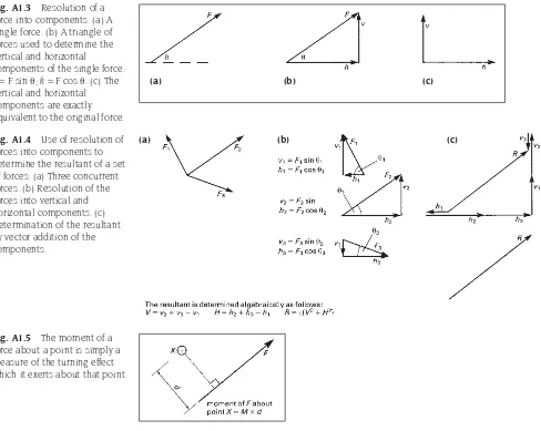
Single forces can be subdivided into parts by reversing the process described above and considering them to be the resultant of two or more components (Fig. A1.3). The technique is called the resolution of the force into its components and it is useful because it allows force systems to be simplified into two sets of forces acting in orthogonal directions (i.e. two perpendicular directions). It also allows the addition of forces to be carried out
algebraically rather than graphically. The resultant of the set of forces in Fig. A1.2, for example, is easily calculated if each of the forces is first resolved into its horizontal and vertical components (Fig. A1.4).
A1.4 Moments of forces
Forces exert a turning effect, called a moment, about points which are not on their line of action. The magnitude of this is equal to the product of the magnitude of the force and the perpendicular distance between its line of action and the point about which the turning effect occurs (Fig. A1.5).
A1.5 Static equilibrium and the
equations of equilibrium
Structures are rigid bodies which are acted upon by external forces called loads. Their response to these depends on the
characteristics of the force system. If the structure is acted upon by no force it may be
129
Fig. A1.3 Resolution of a force into components. (a) A single force. (b) A triangle of forces used to determine the vertical and horizontal
components of the single force: v=Fsin;h=Fcos. (c) The
vertical and horizontal components are exactly equivalent to the original force.
Fig. A1.4 Use of resolution of forces into components to determine the resultant of a set of forces. (a) Three concurrent forces. (b) Resolution of the forces into vertical and horizontal components. (c) Determination of the resultant by vector addition of the components.
Fig. A1.5 The moment of a force about a point is simply a measure of the turning effect which it exerts about that point.
(a)
(a) (b) (c)
regarded as being in a state of rest. If it is acted upon by a single force, or by a group of forces which has a resultant, it moves, (more precisely it accelerates) under their action (Fig. A1.6). The direction of the movement is the
same as that of the line of action of the single force or resultant and the rate of acceleration is dependent on the relationship between the mass of the structure and the magnitude of the force. If the structure is acted upon by a group of forces which has no resultant, that is a group of forces whose ‘triangle of forces’ or ‘polygon of forces’ is a closed figure, it may remain at rest and a state of static equilibrium is said to exist. This is the condition which is required of the force systems which act on real structures although, as will be seen below, the need for the force system to have no resultant
is a necessary but not a sufficient condition for equilibrium.
The loads which act on real structures rarely constitute an equilibrium set by themselves but equilibrium is established by reacting forces which act between the structures and their foundations. These reacting forces are in fact generated by the loads which tend to move the structure against the resisting effect of the supports. The relationship which exists between the loading forces which act on a structure and the reacting forces which these produce at its foundations is demonstrated here in a very simple example, which is illustrated in Fig. A1.7.
The example is concerned with the
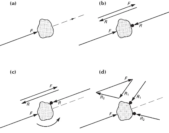
equilibrium or otherwise of a rigid body which is situated on a frictionless surface (a block of wood on a sheet of ice might be a practical example of this). In Fig. A1.7(a), a force (load) is applied to the body and, because the body is resting on a frictionless surface and no
opposing force is possible, it moves in
response to the force. In Fig. A1.7(b) the body encounters resistance in the form of an immovable object and as it is pushed against the object a reaction is generated whose
Fig. A1.6 If a body is acted upon by a force it will accelerate along the line of action of the force. The magnitude of the acceleration depends on the relationship between the mass of the body and the magnitude of the force (Newton’s Second Law of Motion).
130
Fig. A1.7 Reacting forces are passive as they occur only as a result of other forces acting on objects. They are generated at locations where resistance is offered to the movement of the object. Equilibrium will occur only if the disposition of resistance points is such that the acting forces together with the reactions form a closed force polygon and exert no net turning effect on the object. The latter condition is satisfied if the sum of the moments of the forces about any point in their plane is zero. (a) A body accelerating under the action of a force. (b) Acceleration stopped and equilibrium established due to the presence of an immovable object on the line of action of the force. This generates a reaction which is equal and opposite to the acting force. Note the very simple ‘polygon’ of forces which the vector addition of the acting force and reaction produces. (c) Equilibrium is not established if the immovable object does not lie on the line of action of the force F, even though the polygon of forces produces no resultant. The latter means that translational motion will not occur but rotation is still possible. (d) A second immovable object restores equilibrium by producing a second reacting force. Note that the magnitude and direction of the original reaction are now different but the force polygon is still a closed figure with no resultant.
(a) (b)
magnitude increases as the pressure on the object increases until it is equal to that of the acting force. The reaction then balances the system and equilibrium is established.
In this case, because the object providing the resistance happened to lie on the line of action of the acting force, one source of resistance only was required to bring about equilibrium. If the object had not been in the line of action of the force as in Fig. A1.7(c), the reaction would together still have been developed, but the resultant and the reaction would have produced a turning effect which would have rotated the body. A second resisting object would then have been required to produce a second reaction to establish equilibrium (Fig. A1.7(d)). The existence of the new reaction would cause the magnitude of the original reaction to change, but the total force system would nevertheless continue to have no resultant, as can be seen from the force polygon, and would therefore be capable of reaching equilibrium. Because, in this case, the forces produce no net turning effect on the body, as well as no net force, a state of equilibrium would exist.
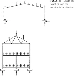
The simple system shown in Fig. A1.7 demonstrates a number of features which are possessed by the force systems which act on architectural structures (Fig. A1.8). The first is the function of the foundations of a structure which is to allow the development of such reacting forces as are necessary to balance the acting forces (i.e. the loads). Every structure must be supported by a foundation system which is capable of producing a sufficient number of reactions to balance the loading forces. The precise nature of the reactions which are developed depends on the
characteristics of the loading system and on the types of supports which are provided; the reactions change if the loads acting on the structure change. If the structure is to be in equilibrium under all possible combinations of load, it must be supported by a foundation system which will allow the necessary reactions to be developed at the supports under all the load conditions.
The second feature which is demonstrated by the simple system in Fig. A1.7 is the set of
conditions which must be satisfied by a force system if it is to be in a state of static
equilibrium. In fact there are just two conditions; the force system must have no resultant in any direction and the forces must exert no net turning effect on the structure. The first of these is satisfied if the components of the forces balance (sum to zero) when they are resolved in any two directions and the second is satisfied if the sum of the moments of the forces about any point in their plane is zero. It is normal to check for the equilibrium of a force system algebraically by resolving the forces into two orthogonal directions (usually the vertical and horizontal directions) and the conditions for equilibrium in a
two-dimensional system can therefore be
summarised by the following three equations:
The sum of the vertical components of all of
the forces = 0
• Fv = 0
The sum of the horizontal components of all of the forces = 0
• Fh = 0
The sum of the moments of all of the forces = 0
• M = 0 131
The two conditions for static equilibrium in a co-planar force system are the physical basis of all elementary structural calculations and the three equations of equilibrium which are derived from them are the fundamental relationships on which all of the elementary methods of structural analysis are based.
A1.6 The ‘free-body-diagram’
In the analysis of structures, the equations which summarise the conditions for
equilibrium are used in conjunction with the concept of the ‘free-body-diagram’ to calculate the magnitudes of the forces which are present in structures. A ‘free-body-diagram’ is simply a diagram of a rigid object, the ‘free body’, on which all the forces which act on the body are marked. The ‘free body’ might be a whole structure or part of a structure and if, as it must be, it is in a state of equilibrium, the forces which act on it must satisfy the conditions for equilibrium. The equations of equilibrium can therefore be written for the forces which are present in the diagram and can be solved for any of the forces whose magnitudes are not known. For example, the three equations of equilibrium for the structure illustrated in Fig. A1.9 are:
Vertical equilibrium:
R1+ R2= 10 + 10 + 5 (1)
Horizontal equilibrium:
R3– 20 = 0 (2)
Rotational equilibrium (taking moments about the left support):
10⫻2 + 10⫻4 + 5⫻6 – 20⫻1 – R2⫻8 = 0 (3)
The solutions to these are:
from equation (3), R2= 8.75 kN
from equation (2), R3= 20 kN
from equation (1), by substituting for R2, R1= 16.25 kN
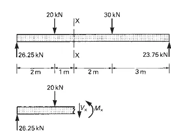
A1.7 The ‘imaginary cut’ technique
The ‘imaginary cut’ is a device for exposing internal forces as forces which are external to a free body which is part of the structure. This renders them accessible for analysis. In its simplest form this technique consists of imagining that the structural element is cut through at the point where the internal forces are to be determined and that one of the resulting two parts of it is removed. If this were done to a real structure the remaining part would, of course, collapse, but in this
technique it is imagined that such forces as are necessary to maintain the remaining part in equilibrium in its original position, are applied to the face of the cut (Fig. A1.10). It is reasoned
132
Fig. A1.9 Free-body-diagram of a roof truss.
that these forces must be exactly equivalent to the internal forces which acted on that cross-section in the structure before the cut was made and the device of the imaginary cut therefore makes the internal forces accessible for equilibrium analysis by exposing them as forces which are external to a part of the structure. They then appear in the ‘free-body-diagram’ (see Section A1.6) of that part of the structure and can be calculated from the equations of equilibrium.
In the analysis of large structural
arrangements the device of the ‘imaginary cut’ is used in several stages. The structure is first subdivided into individual elements (beams, columns, etc.) for which free-body-diagrams are drawn and the forces which pass between the elements are calculated from these. Each element is then further sub-divided by ‘imaginary cuts’ so that the internal forces at each cross-section can be determined. The procedure is summarised in Fig. 2.18.