MATCHING REAL AND SYNTHETIC PANORAMIC IMAGES USING A VARIANT OF GEOMETRIC HASHING J. Li-Chee-Ming, C. Armenakis
Geomatics Engineering, GeoICT Lab
Department of Earth and Space Science and Engineering Lassonde School of Engineering, York University Toronto, Ontario, M3J 1P3
{julienli}, {armenc} @yorku.ca
KEYWORDS: Photogrammetry, sensor orientation, navigation, registration, model-based tracking, geometric hashing ABSTRACT:
This work demonstrates an approach to automatically initialize a visual model-based tracker, and recover from lost tracking, without prior camera pose information. These approaches are commonly referred to as tracking-by-detection. Previous tracking-by-detection techniques used either fiducials (i.e. landmarks or markers) or the object’s texture. The main contribution of this work is the development of a tracking-by-detection algorithm that is based solely on natural geometric features. A variant of geometric hashing, a model-to-image registration algorithm, is proposed that searches for a matching panoramic image from a database of synthetic panoramic images captured in a 3D virtual environment. The approach identifies corresponding features between the matched panoramic images. The corresponding features are to be used in a photogrammetric space resection to estimate the camera pose. The experiments apply this algorithm to initialize a model-based tracker in an indoor environment using the 3D CAD model of the building.
1 INTRODUCTION TO MODEL-BASED TRACKING Model-based visual tracking is typically used to obtain the position and the orientation (pose) of the camera when a complete or partial model of the environment pre-exists. Common applications of model-based tracking include indoor positioning, augmented reality (AR), robot navigation (e.g. automotive), and robotic object manipulation. Lepetit et al. (2005) reviewed the status of model-based rigid body tracking from 1990 to 2005. Lahdenoja et al. (2015) reviewed the advances of model-based tracking from 2005 to 2014. Treiber (2010), Chin and Dyer (1986), and Besl and Jain (1985) provide comprehensive surveys of model-to-image matching and registration. A typical workflow of model-based tracking is: 1) In the initialization phase, the initial camera pose is
estimated without knowledge of the previous pose. Corresponding features (e.g. points or lines) between a camera’s image and the 3D model are found either manually or automatically. The pose is resolved from the correspondences, for example using photogrammetric space resection via the collinearity equations.
2) In the frame-to-frame tracking phase, the camera pose is constantly updated by maintaining the model-to-image correspondences when the camera moves. As in the initialization phase, the pose is resolved from the correspondences.
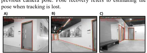
Li-Chee-Ming and Armenakis (2016) provide an application of a model-based tracker called ViSP (Visual Servoing Platform) (Comport et al., 2003), for pose estimation in indoor environments. ViSP uses the camera pose from the previous epoch to back-project a 3D model onto the current epoch’s image. Edges are matched between the image and the back-projected model. Corresponding edges are used to estimate the camera pose of the current frame. Figure 1 shows experimental results. As ViSP is a sequential algorithm, requiring the camera pose from the previous epoch, a user must manually input the camera pose at the initialization and recovery phases. This work proposed a solution that automats these processes.
Initialization and Recovery 1.1
Initialization is performed when the tracking starts; the initial pose of the system is estimated without knowledge of the
previous camera pose. Pose recovery refers to estimating the pose when tracking is lost.
Figure 1. Sample frames demonstrating the ViSP model-based tracker. The second floor of York University’s Bergeron Building is being observed, the 3D building model is projected onto the image plane (red lines) using the previous epoch’s camera pose, matching is performed and the current camera pose is estimated (Li-Chee-Ming and Armenakis, 2016).
Both Lepetit et al. (2005) and Lahdenoja et al. (2015) mention that initialization and recovery is often done manually. Automated techniques, referred to as tracking-by-detection, are divided into two categories:
1) View-based, are edge-based techniques, where edges extracted from current frame are matched with 2D views of the 3D model previously obtained from different positions and orientations (Wiedemann et al. (2008), Petit (2013)). 2) Keypoint-based, where keypoints (i.e. image features
invariant to scale, viewpoint and illumination changes) extracted from the current frame are matched against a database of keypoints extracted from images of the object taken at different positions and orientations (Skrypnyk and Lowe, 2004).
In both cases, the matches provide the 2D to 3D correspondences needed for camera pose estimation. The difficulty in implementing such approaches comes from the fact that the database of model images and the incoming images may have been acquired from very different viewpoints. The wide baseline matching problem becomes a critical issue that must be addressed. A more comprehensive survey of model-based initialization can be found in Euranto et al. (2014).
specular materials, which is not necessarily true of texture-based methods. Lahdenoja et al. (2015) also identified that tracking-by-detection techniques commonly use either fiducials (i.e. landmarks or markers) or the object’s texture is used. The main contribution of this work is the development of a tracking-by-detection algorithm that is based solely on natural geometric features.
2 METHODOLOGY
The proposed strategy to finding correspondence between the 3D indoor model and an image is as follows:
1) In the pre-processing phase, generate a database of features extracted from panoramic images of the 3D indoor model, referred to in this work as synthetic panoramic images, captured from various vantage points in the 3D model. 2) In the model-based tracker’s initialization phase:
a. Capture a set of images by rotating an RGB camera 360 degrees about its vertical axis.
b. Generate a panoramic image (e.g. using OpenCV). c. Extract features from the panoramic image and match
them with the model features in the database of synthetic panoramic images using geometric hashing. d. Determine the camera pose through photogrammetric
space resection using the retrieved model features as ground control.
It was decided to extract features from panoramic images instead of individual images because geometric hashing searches the database for a group of features extracted from an image; a larger field of view allows for each group to contain a larger number of features. This increases the distinctiveness of the group of features, and in turn increases the probability of retrieving the correct model from the database.
Geometric hashing (Wolfson and Rigoutsos, 1997) has been widely used to identify feature correspondences between an image and a 3D model. It is a simple, efficient, and robust feature pattern matching method between two datasets. Matching is possible even when features have undergone geometric transformations (scale, rotation, and translation) or are partially occluded. Further, this method has low computational complexity as it is inherently parallel. Performing the search using multiple cooperating processors has been implemented (Lamdan et al., 1990). Cham et al. (2010) demonstrate an increase in search speed, at the expense of accuracy, when geometric hashing is used in the matching stage of their 2D pose estimation framework. This suggested that a step is required to refine the pose estimate provided by geometric hashing. Recently, Jung et al. (2016) enhanced geometric hashing using context features and an additional similarity function to improve approximate registration parameters between aerial images and 3D building models.
Geometric hashing provides only the search engine portion of an object recognition system; the representation and extraction of the features are crucial inputs to geometric hashing. The following section explains the choice of features as they depend on the available models and collected data. Subsequent sections explain the general geometric hashing algorithm, and the modifications made to suit the specific application of navigation in GPS-denied indoor environments.
3 FEATURE SELECTION
The textures of the building models often have little correlation with the imagery captured at a different time because of changes
in illumination, along with the presence of shadows. Further, the colours of environment may change with time, for example when walls are painted. However, the shape of the building remains constant in time and is more suitable for matching. Thus, this work focuses on matching geometric features (points, lines, polygons, etc.), as opposed to intensity-based features such as SIFT (Lowe, 1999). This is convenient as 3D models generally provide a database of georeferenced vertices (points), edges (lines), and faces (polygons).
Extracting feature points with a corner detector, such as Harris corners (Harris and Stephens, 1988), from an incoming image would yield many unwanted points from objects in the environment which are not included in the model, for example chairs and other furniture. To consider matching polygons, a robust solution is required that could handle a variety of noise, occlusions, and incomplete or unclosed figures. Such a method would increase the complexity and run-time of the system. Line matching approaches are divided into algorithms that match individual line segments and algorithms that match groups of line segments. Matching single lines is based on geometric properties, such as orientation, length, and extent of overlap. Matching groups of lines takes away the ambiguity involved by providing both pattern associations and geometric information. Graph-matching is a common approach, as graphs capture relationships such as left of and right of, and topological connectedness (Baillard et al., 1999).
Feature Extraction 3.1
Linear features were chosen to establish correspondence between the 3D model and the image. The chosen linear feature, referred to in this work as the Vertical Line Feature, consists of two end points connected by a vertical line. In agreement with Cham et al. (2010), Vertical Line Features were chosen because vertical lines commonly appear in structured environments. Further, vertical lines in the environment remain vertical in a cylindrical panoramic image, while horizontal lines in the environment become curved.
Various approaches may be used to extract vertical lines from the images. Leung et al. (2008) use vanishing point analysis to extract horizontal and vertical lines from an image; however they demonstrate that this requires a lot of processing power to realize a real-time system. Other line extraction techniques may also be used, such as the Hough Line Transform (Duda and Hart, 1972), the Progressive Probabilistic Hough Transform (Matas et al., 2000), or the Line Segment Detector (Von Gioi et al., 2010).
Figure 3. A) Synthetic panoramic image of Room B1 with extracted Vertical Line Features. B) Incoming panoramic image of Room B1 with extracted Vertical Line Features. C) Similarity transformation: 2D hash table populated using Vertical Line S2 as a 2-point basis from the synthetic panoramic image, and Vertical Line R1 from the incoming panoramic image. D) Affine transformation: 2D hash table populated using Vertical Line S2 (and the top corner from its duplicate Line S11) from the synthetic panoramic image as 3-point basis, and Vertical Line R1 (and the top point from its duplicate Line R10) from the incoming panoramic image. E) Projective transformation: 2D hash table populated using Vertical Line S2 (and its duplicate Line S11) from the synthetic panoramic image as a 4-point basis, and Vertical Line R1 (and its duplicate Line R10) from the incoming panoramic image. F) Series generated from the number of Vertical Line Features of the model and G) from the number of Vertical Line Features of the incoming image. Each element of the series is the number of Vertical Lines features in Table E) projected into the 1D hash table’s bin size of 0.04.
Synthetic Panoramic Images of the 3D model 3.2
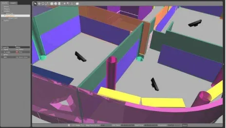
To generate the database of synthetic panoramic images, 3D indoor building models were loaded into the Gazebo Robot Platform Simulator (Open Source Robotics Foundation, 2014), which is a 3D simulator with a physics engine. Gazebo is capable of simulating robots and a variety of sensors in complex and realistic indoor and outdoor environments. For each indoor model, such as the Bergeron Centre building shown in Figure 2, an equally spaced grid of simulated Kinect sensors was spread across the extent of the model. At each grid location, the Kinect rotated 360 degrees at 60 degree intervals and captured a synthetic image at each interval. The known poses of each image were used to automatically generate cylindrical panoramic images for each grid location. Vertical Line Features were extracted from each synthetic panoramic image and stored in a hash table. Figure 3A) shows a synthetic panoramic image captured in Room B1 of the Bergeron Centre. The figure also shows the extracted Vertical Line Features using green lines.
4 GEOMETRIC HASHING
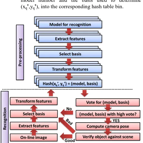
The geometric hashing algorithm is divided into two stages: The pre-processing phase that generates the database, and the recognition phase that processes incoming images. The process’ flow chart is provided in Figure 4 and the algorithm is summarized in the subsequent sections (Wolfson and Rigoutsos, 1997).
The Pre-Processing Phase 4.1
For each model, which is a synthetic panoramic image in this work, do the following:
1) Extract point features.
a. Compute the coordinates (x', y') of the remaining features in a canonical reference frame Oxy defined by the basis.
b. After appropriate quantization, use the coordinates (xq',yq') as an index into a 2D hash table data structure and insert the information (M, basis), namely the model number and the basis used to determine (xq',yq'), into the corresponding hash table bin.
Figure 4. Flow chart for the geometric hashing algorithm. (modified from Lamdan et al., 1990).
The Recognition Phase 4.2
When presented with an input image, do the following: 1) Extract point features from the image.
2) Choose an arbitrary basis from the extracted features: 2 points when assuming objects undergo similarity transformation, 3 points for affine transformation, or 4 points for projective transformation.
3) Compute the coordinates of the remaining feature points in a canonical reference system Oxy defined by the basis. 4) Suitably quantize each such coordinate and access the
appropriate hash table bin; for every entry found there, cast a vote for the (model, basis) combination. Potential matches correspond to the (model, basis) combinations that receive more than a certain number of votes.
5) For each potential match, recover the transformation (i.e., the camera pose) that results in the best least-squares match between all corresponding feature pairs.
6) Transform the features of the model according to the recovered transformation and verify them against the input image features. If the verification fails, return to step 2 using a different image basis pair. If the verification passes, process the next image.
Selecting the Geometric Transformation 4.3
According to the geometric hashing algorithm, an input image will retrieve its corresponding model from the database if a matching function finds a canonical coordinate system, Oxy, where corresponding model features and image features have the same positions, i.e. they fall into the same bin when they are transformed to Oxy. In order for the features to coincide, they must undergo a rotation, translation, and scaling, in two
dimensions. In the simplest case, a 4 degree of freedom (dof) similarity transformation may be used.
To estimate the four similarity transformation parameters for the model, two points belonging to the model are chosen to define a canonical frame of reference. For instance, the top and bottom corners of Vertical Line Features can be used to form the basis. For example, Figure 3A) shows Model B1. Figure 3C) shows the 2D hash table that is generated using Model B1’s Vertical Line Feature S2, consisting of points P1 (its top point) and P2 (its bottom point), as the ordered basis. The Vertical Line Feature is scaled so that P2'P1 =1 in the Oxy system. The midpoint between P1 and P2 is placed at the origin of Oxy in such a way that the vector P2'P1' has the direction of the positive y axis. That is, the (x, y) image coordinate of P1 and P2 in the Model B1 are transformed to P1'= (0, 0.5) and P2'= (0, -0.5) in the Oxy system, respectively. These corresponding points are used to solve for the similarity transformation parameters. The remaining Vertical Line Features of Model B1 (green lines in Figure 3A), to be used as support, are transformed to Oxy via the transformation parameters. In the quantized hash table, a record is kept in each of the bins where the remaining points land, noting that model B1 with Vertical Line Feature S2, expressed as (B1, S2), yields an entry in this bin.
Due to occlusions, it is not guaranteed that both model points P1 and P2 will appear in an image where Model B1 is present during the recognition phase. Consequently, the model’s features are encoded in all possible ordered basis pairs. Namely, the hash table contains entries of the form (B1, S1), (B1, S3), (B1, S4), and so on. The same process is repeated for the remaining models in the database (i.e. B2, B3, B4, etc.). Each hash table bin has a list of entries of the form (model, basis). Some hash table bins may receive more than one entry. As a result, each bin will contain a list of entries of the form (model, basis).
Geometric hashing can be applied to many other transformations. The main difference is the number of points used to define the basis for the reference frame. Specifically: • 2-dof translation uses a one-point basis, mapping model
point P1(x, y) to P1' (0, 0).
• 3-dof translation and rotation uses a two-point basis, mapping model point P1(x, y) to P1'(0, 0.5), and P2(x, y) to P2'(0, -0.5).
• 4-dof similarity transformation uses a two-point basis, mapping model point P1(x, y) to P1'(0, 0.5), and P2(x, y) to P2'(0, -0.5).
• 6-dof affine transformation uses a three-point basis, mapping model point P1(x, y) to P1'(-0.5, 0.5), P2(x, y) to P2'(-0.5, -0.5), and P3(x, y) to P3'(0.5, 0.5).
• 8-dof projective transformation uses a four-point basis, mapping model point P1(x, y) to P1'(-0.5, 0.5), P2(x, y) to P2'(-0.5, -0.5), P3(x, y) to P3'(0.5, 0.5), and P4 to P4'(0.5, -0.5).
is also a viable choice in indoor environments as fewer points are needed to define the basis, which increases the probability that all of the basis points extracted from the image will be present in the model. Further, the affine transformation parameters can be more accurate as less error is propagated from the image measurements of the basis points. Many investigators suggest that the nonlinear perspective projection can be accurately substituted with a linear affine approximation when the relative depth of object features is small compared to the distance of the object from the camera (David et al., 2002). Figures 3 C) to E) provide an assessment of the performances of the similarity, affine, and projective transformations, respectively.
Estimating the 8 projective transformation parameters requires four 2D points; this implies that image-to-model matching will succeed if the top and bottom points of two Vertical Line Features extracted from the image are present in the 3D model. Li-Chee-Ming and Armenakis (2014) suggested that improved performance is achieved if the two Vertical Line Features chosen from the image as a basis are spread across the image, with the supporting features located in between the two Vertical Line Features chosen as a basis. Further, the two Vertical Line Features chosen as a basis should be relatively long compared to the other features. This behaviour is expected, as transforming the supporting features in these conditions becomes analogous to an interpolation, as opposed to a less accurate extrapolation. As a result of this finding, it was decided to extract both model and image Vertical Line Features from 360 degree panoramic images. A larger field of view allows for an increased number of features to be present in the image, and increased the maximum separation between the Vertical Line Features used as a basis.
Improvement using an Enhanced Geometric Hashing 4.4
This section describes a novel improvement of the geometric hashing algorithm. The probability of finding a correct match in the database is increased while decreasing the size of the database. The incoming panoramic and the synthetic panoramic images were captured such that they began and ended at the same pose, i.e. the horizontal field of view is 360 degrees. This allowed a panoramic image to be concatenated with itself. Consequently, each Vertical Line Feature appeared twice, separated by all of the other Vertical Line Features, in the panoramic image. This presented the following benefit: instead of the four point basis consisting of two different Vertical Line Features, only one Vertical Line Feature was used to estimate the perspective transformation parameters. That is, the top and bottom point of a Vertical Line Feature mapped to two points of the basis, the other two points were mapped to the duplicated Vertical Line Feature belonging to the concatenated panoramic image. Only the lines in between these two Vertical Line Features were projected to the hash table and used as support. The probability of finding a match is increased in this case as only one Vertical Line Feature needs to be matched instead of two. For example, Figure 3A) shows a synthetic panoramic image of room B1, Vertical Line Feature S2 and its duplicate S11 are used as a basis for the model data. All of the model lines in between these two lines (i.e., Lines S3 to S10) are projected into the canonical coordinate system (green lines in Figure 3E)). Similarly, Figure 3B) shows a panoramic captured of Room B1, Line R1 and its duplicate Line R10 are used as a basis for the input image data. All of the lines in between the two basis lines (i.e., Lines R2 to R9) are projected into the canonical coordinate system (red lines in Figure 3E)). It is evident that the image features and corresponding model
features do not exactly coincide. This is due to error from the model, the quantization error of the hash table, error in the image measurements, and occlusions. The size of the bin is a critical parameter. If the bins are too large, then there will be too many false positives. If the bins are too small, then there is insufficient provision for noise in the input. Results in Table 2 are from using the conventional geometric hashing voting approach (Lamdan et al., 1990). Using the corner points of Vertical Line Features produced many false candidates in the recognition phase because the required search area was large. However, the majority of this error was in the vertical axis because the model’s corner points were often not visible in the real image as they were occluded by clutter in the environment. In an effort to reduce the number of model candidates returned from the voting stage, a different voting strategy was developed that leveraged the use of vertical lines instead of individual points: A smaller search area extended only in the horizontal direction. That is, a (model, basis) combination received a vote if the midpoint of an image line was within a certain horizontal distance from one of its supporting model lines’ midpoints. Experimentation revealed that the average horizontal error separating corresponding image and model lines in the canonical coordinate system was 0.04±0.02 units. Thus the bin size was chosen to be 0.04 units. Notably, this strategy reduced the 2 dimensional search space to 1 dimension (e.g. a 25 bin hash table as shown in Figure 3F) for the model data and 3G) for the image data. This reduced the size of the database and the search time.
The Similarity Function 4.5
A score function was introduced to measure the similarity between the supporting model data and the supporting image data. Geometric hashing’s similarity score is based simply on counting the number of votes, which is not sufficient because it depends only on the number of supporting lines. In other words, the probability of an image matching a certain model increases as the number of (image and model) features increases because the probability of an image feature projecting into a model feature’s bin increases. A standardized scoring method was required, one that did not depend on the number of features in the image or model. The chosen similarity score was the normalized cross-correlation (NCC) (Lewis, 1995). Specifically, a series of numbers was generated from the hash table (e.g., 25 numbers long for a bin size of 0.04). Each element of the series contained the number of lines in the bin. For example, Figure 3F) shows the series generated from the model’s supporting data in green. Figure 3G) shows the series generated from the image’s supporting data in red.
column implies that for Image Line R1, the best matching model line in this particular synthetic panoramic image is Model Line S2. An image-model line pair could be considered candidate matches if one or, more stringently, both of these conditions are met. To further increase the stringency, one could compare the highest NCC coefficient against the second highest NCC coefficient in a row/column. There is more confidence in an image-model line match if its NCC coefficient is much higher than the NCC coefficient of any other match in its row and column, for example 20% higher.
R9 R1 R2 R3 R4 R5 R6 R7 R8
Table 1. Table of NCC coefficients used to identify corresponding Vertical Line Features from the input panoramic image and synthetic panoramic image captured in Room B1.
5 EXPERIMENTS
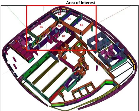
Images were collected using a Microsoft Kinect’s RGB camera (640x480 pixel resolution). A panoramic image was captured in 6 locations of the Bergeron Centre: Rooms B1 to B6 as shown in Figure 5. The objective of the experiment was to identify the location that each panoramic image was captured by retrieving the panoramic image’s corresponding synthetic panoramic image from a database. Corresponding features are also identified between the incoming panoramic image and the synthetic panoramic image retrieved from the database. These corresponding features are to be used to initialize the camera pose of a model-based tracker in a subsequent process.
The 3D CAD design plan of the Bergeron Centre of Engineering Excellence was used as the known 3D map of the environment. It is a TIN model consisting of the building’s architectural components (walls, windows, doors, etc.), and structural components (concrete slabs and pillars, etc.). This 3D CAD model served two purposes in the proposed approach. Firstly, it provides the necessary level of detail of linear features (vertical lines) for feature matching. Secondly, it provided ground control points to photogrammetrically achieve sub-meter accuracies of the camera’s exterior orientation’s positional elements. The geometric accuracy of the building models is in the order of 1-10 cm.
# of candidate matches
B1 B2 B3 B4 B5 B6
Table 2. Conventional geometric hashing: Truth table of the matching process.
Figure 5. Area of interest in the Bergeron Centre for the experiments. Panoramic images were captured in rooms B1, B2, B3, B4, B5, and B6.
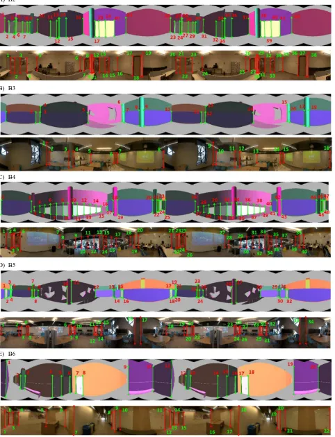
The RGB images were stitched together to generate a single 360 degree panoramic image, this was accomplished in real-time using OpenCV’s implementation of (Brown and Lowe, 2007). Figure 6 shows the input panoramic images and corresponding synthetic panoramic images. Vertical Line Features extracted from synthetic panoramic images and input panoramic image are shown with green lines and red lines, respectively.
Results from using the approach of (Gavrilla and Groen, 1992) shown in Table 2, revealed that using the corner points of Vertical Line Features in geometric hashing’s conventional voting strategy produced many false candidates in the recognition phase because the required search area was large. Further correct matches could not be reliably identified. Table 3 reveals that matching panoramic and synthetic panoramic images using the proposed approach produced more true positives (i.e., accepted correct matches) than false positives (i.e., accepted incorrect matches), and more true negatives (rejected incorrect matches) than false negatives (i.e., rejected correct matches). Candidate matches were selected if their NCC value was higher than 0.8, and their NCC was the highest in its row and column. The results indicate that there are outlier matches in the list of candidate image-to-model line matches. However, when a panoramic image was considered to match the synthetic panoramic image that produced the largest number of candidate image-to-model line matches, the match was always correct in this dataset.
# of candidate matches
B1 B2 B3 B4 B5 B6
A) B2
B) B3
C) B4
D) B5
E) B6
6 CONCLUSIONS
This work proposed an enhanced variant of geometric hashing to determine correspondence of vertical lines between an incoming panoramic image of an indoor environment and a synthetic panoramic image captured from the 3D model of the same environment. The improvement is based on the panoramic geometry of the scene and a voting strategy that uses the separation of vertical lines instead of individual points in the hashing table. An additional score function was introduced to improve the geometric hashing’s similarity based only on the counting of the number of bin votes. The approach identifies corresponding features without requiring an initial approximate camera pose. The resulting corresponding features are to be used in a photogrammetric space resection to initialize a model-based camera pose tracking system. Future work includes developing a similar process that uses the Kinect’s depth camera data in the pose initialization and recovery phases.
ACKNOWLEDGMENTS
NSERC’s financial support for this research work through a Discovery Grant is much appreciated. We thank Planning & Renovations, at York University for providing the 3D model of the Bergeron Centre.
REFERENCES
Baillard C, Schmid C, Zisserman A, and Fitzgibbon A. 1999. Automatic line matching and 3D reconstruction of buildings from multiple views, Proc. ISPRS Conference on Automatic Extraction of GIS Objects from Digital Imagery, 32: 69-80.
Besl P, and Jain R. 1985. Three-Dimensional Object Recognition, ACM Computing Survey, 17 (1): 75-154.
Brown M, and Lowe D. 2007. Automatic panoramic image stitching using invariant features, International Journal of Computer Vision, 74(1): 59-73.
Cham T, Arridhana C, Tan W, Pham M, and Chai L. 2010. Estimating camera pose from a single urban ground-view onmidirectional image and a 2D building outline map, Proc. IEEE Conf. on Computer Vision and Pattern Recognition.
Chin R, and Dyer C. 1986. Model-based recognition in robot vision, ACM Computing Survey, 18(1): 67-108.
Comport A, Marchand E, and Chaumette F. 2003. Robust and real-time image-based tracking for markerless augmented reality. Technical Report 4847. INRIA.
David P, DeMenthon D, Duraiswami R, and Samet H. 2002. SoftPOSIT: Simultaneous Pose and Correspondence Determination, European Conf. on Computer Vision (ECCV), Copenhagen, Denmark, pp. 698-714.
Duda O and Hart P. 1972. Use of the Hough Transformation to Detect Lines and Curves in Pictures. Comm. ACM, pp. 11–15.
Euranto A, Lahdenoja O, and Suominen R. 2014. Model-based tracking initialization in ship building environment. In: University of Turku Technical Reports 2.
Harris C, and Stephens M. 1988. A combined corner and edge detector. Alvey Vision Conference, pp. 147-152.
Jung J, Sohn, G, Bang K, Wichmann A, Armenakis C, and Kada M. 2016. Matching Aerial Images to 3D Building Models Using Context-Based Geometric Hashing. Sensors 2016, 16, 932.
Lahdenoja O, Suominen R, Säntti T, and Lehtonen T. 2015. Recent Advances in Monocular Model-Based Tracking: A Systematic Literature Review. University of Turku Technical Reports, No. 8.
Lamdan, Y., J. Schwartz, and H. Wolfson, 1990. Affine invariant model-based object recognition, IEEE Trans. Robotics and Automation, 6(1): 578-589.
Lepetit V, and Fua P. 2005. Monocular model-based 3d tracking of rigid objects: A survey. In: Foundations and trends in computer graphics and vision, pp. 1–89.
Leung K, Clark C, and Huisson J. 2008. Localization in urban environments by matching ground level video images with an aerial image, Proc. IEEE Int. Conf. on Robotics and Automation, pp. 551-556.
Lewis, J.P., 1995. Fast Normalized Cross-Correlation, Vision Interface.
Li-Chee Ming J, and Armenakis C. 2014. Feasibility study for pose estimation of small UAS in known 3D environment using geometric hashing. Photogrammetric Engineering & Remote Sensing, 80(12): 1117–1128.
Li-Chee-Ming J, and Armenakis C. 2016. Augmenting ViSP’s 3D Model-Based Tracker with RGB-D SLAM for 3D Pose Estimation in Indoor Environments. ISPRS Archives, Vol XLI-B, pp 925-932.
Lowe D. 1999. Object recognition from local scale-invariant features, 7th Conference on Computer Vision, pp.1150-1157.
Matas J, and Galambos C, and Kittler J. 2000. Robust Detection of Lines Using the Progressive Probabilistic Hough Transform. CVIU 78 1, pp 119-137.
Open Source Robotics Foundation. 2014. Gazebo, robot simulation made easy. www.gazebosim.org. Accessed 1/1 2017.
Petit A. 2013. Robust visual detection and tracking of complex object: applications to space autonomous rendez-vous and proximity operations. PhD Thesis, Université de Rennes 1.
Skrypnyk I, and Lowe D. 2004. Scene modelling, recognition and tracking with invariant image features. ISMAR,pp.110-119.
Treiber M. 2010. Introduction to Object Recognition. Springer-Verlag London Limited, 220 p.
Von Gioi R, Jakubowicz J, Morel J, Randall G. 2010. LSD: A Fast Line Segment Detector with a False Detection Control, IEEE Trans. Pattern Analysis and Machine Intelligence, 32 (4):722-732.
Wiedemann U, and Steger C. 2008. Recognition and tracking of 3D objects, Lect. Notes Comp. Sci., vol. 5096, pp. 132-141.