Principle:
A square wave voltage of low fre-quency is applied to oscillatory cir-cuits comprising coils and capacitors to produce free, damped oscillations. The values of inductance are calcu-lated from the natural frequencies measured, the capacitance being known.
Tasks:
To connect coils of different dimen-sions (length, radius, number of turns) with a known capacitance C to form an oscillatory circuit. From the measurements of the natural fre-quencies, to calculate the
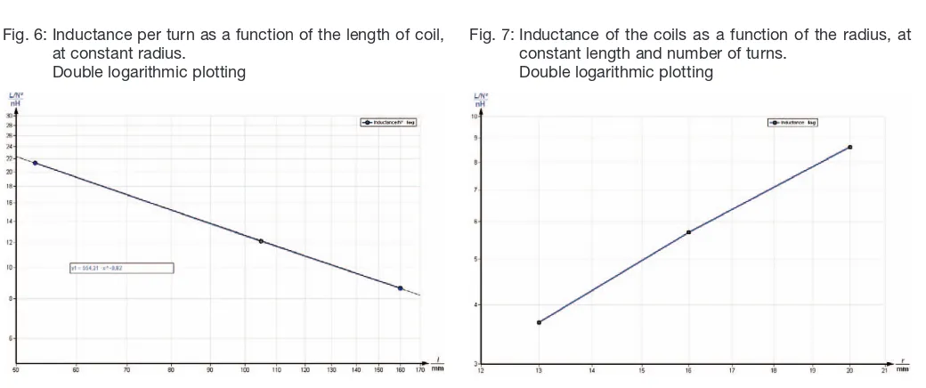
induc-Inductance per turn as a function of the length of the coil at constant radius.
tances of the coils and determine the relationships between:
1. inductance and number of turns 2. inductance and length 3. inductance and radius.
What you can learn about …
Lenz’s law
Experiment P2440311 with FG-Module
Experiment P2440301 with oscilloscope
Function generator 13652.93 1
Oscilloscope, 30 MHz, 2 channels 11459.95 1
Adapter, BNC-plug/socket 4 mm 07542.26 1
Induction coil, 300 turns, d= 40 mm 11006.01 1 1
Connection box 06030.23 1 1
Connecting cord, l= 250 mm, red 07360.01 1 1 Connecting cord, l= 250 mm, blue 07360.04 1 1 Connecting cord, l= 500 mm, red 07361.01 2 2 Connecting cord, l= 500 mm, blue 07361.04 2 2
Cobra3 Basic Unit 12150.00 1
Power supply, 12 V- 12151.99 2
RS232 data cable 14602.00 1
Cobra3 Universal writer software 14504.61 1
Measuring module function generator 12111.00 1 PC, Windows® 95 or higher
What you need:
Complete Equipment Set, Manual on CD-ROM included
Inductance of solenoids with Cobra3
P24403 01/11
Related topics
Law of inductance, Lenz’s law, self-inductance, solenoids, transformer, oscillatory circuit, resonance, damped oscillation, logarithmic decrement, Qfactor.
Principle
A square wave voltage of low frequency is applied to oscilla-tory circuits comprising coils and capacitors to produce free, damped oscillations. The values of inductance are calculated from the natural frequencies measured, the capacitance being known.
Equipment
Induction coil, 300 turns, d= 40 mm 11006.01 1 Induction coil, 300 turns, d= 32 mm 11006.02 1 Induction coil, 300 turns, d= 25 mm 11006.03 1 Induction coil, 200 turns, d= 40 mm 11006.04 1 Induction coil, 100 turns, d= 40 mm 11006.05 1 Induction coil, 150 turns, d= 25 mm 11006.06 1 Induction coil, 75 turns, d= 25 mm 11006.07 1 Coil, 1200 turns 06515.01 1 Oscilloscope, 30 MHz, 2 channels 11459.95 1 Function generator 13652.93 1 Capacitor /case 1/ 470 nF 39105.20 1 Adapter, BNC-plug/socket 4 mm 07542.26 1
Connection box 06030.23 1
Connecting cord, l= 250 mm, red 07360.01 1
Connecting cord, l= 500 mm, red 07361.01 2 Connecting cord, l= 250 mm, blue 07360.04 1 Connecting cord, l= 500 mm, blue 07361.04 2
Tasks
To connect coils of different dimensions (length, radius, num-ber of turns) with a known capacitance C to form an oscilla-tory circuit. From the measurements of the natural frequen-cies, to calculate the inductances of the coils and determine the relationships between
1. inductance and number of turns 2. inductance and length
3. inductance and radius.
Set-up and procedure
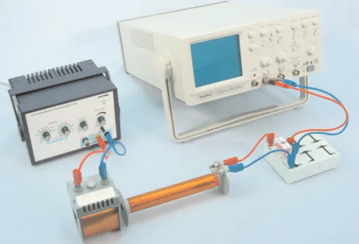
Set up the experiment as shown in Fig. 1 + 2.
A square wave voltage of low frequency (f≈500 Hz) is applied to the excitation coil L. The sudden change in the magnetic field induces a voltage in coil L1 and creates a free damped oscillation in the L1C oscillatory circuit, the frequency fo of
which is measured with the oscilloscope.
Coils of different lengthsl, diameters 2rand number of turns
Nare available (Tab. 1). The diameters and lengths are meas-ured with the vernier caliper and the measuring tape, and the numbers of turns are given.
Tab. 1: Table of coil data
The following coils provide the relationships between induct-ance and radius, length and number of turns that we are in-vestigating:
1.) 3, 6, 7 L = f(N)
2.) 1, 4, 5 L/N2 = f(l) 3.) 1, 2, 3 L = f(r)
As a difference in length also means a difference in the num-ber of turns, the relationship between inductance and numnum-ber of turns found in Task 1 must also be used to solve Task 2.
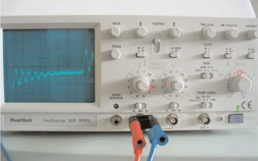
Fig. 3 shows an measurement example and the oscilloscope settings:
- Input: CH1
- Volts/div 10 mV
- Time/div <0.1 ms
- Trigger source CH1
- Trigger mode Norm
The oscilloscope shows the rectangular signal and the dam-ped oscillation behind each peak. Determine the frequency f0
of this damped oszillation.
where Tis the oscillation period.
f0
1
T
Fig. 2: Set-up for inductance measurement.
Fig. 3: Oscilloscope settings.
Coil No. N Cat. No.
1 300 40 160 11006.01
2 300 32 160 11006.02
3 300 26 160 11006.03
4 200 40 105 11006.04
5 100 40 53 11006.05
6 150 26 160 11006.06
7 75 26 160 11006.07
l
mm 2r
Notes
The distance between L1 and L should be as large as possi-ble so that the effect of the excitation coil on the resonant fre-quency can be disregarded. There should be no iron compo-nents in the immediate vicinity of the coils.
The tolerance of the oscilloscope time-base is given as 4%. If a higher degree of accuracy is required, the time-base can be calibrated for all measuring ranges with the function generator and a frequency counter prior to these experiments.
Theory and evaluation
If a current of strength Iflows through a cylindrical coil (sole-noid) of lengthl, cross sectional area A= p· r2, and number
of turns N, a magnetic field is set up in the coil. When l>> r
the magnetic field is uniform and the field strength His easy to calculate:
(1)
The magnetic flux through the coil is given by
' = mo· m· H· A (2)
where mo is the magnetic field constant and mthe absolute
permeability of the surrounding medium.
When this flux changes, it induces a voltage between the ends of the coil,
(3)
where
(4)
is the coefficient of self-induction (inductance) of the coil.
Inductivity Equation (4) for the inductance applies only to very long coils l>> r, with a uniform magnetic field in accordance with (1).
Lm0 · m · p ·
N2 ·
r2
l L · I
N · m0 · m · A · N
l · I
Uind. N · £
HI · N
l
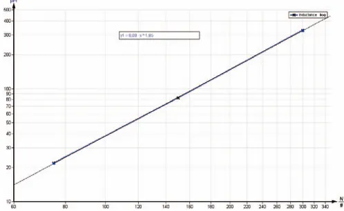
Fig. 4: Inductances of the coils as a function of the number of turns, at constant length and constant radius.
Double logarithmic plotting.
Fig. 6: Inductance of the coils as a function of the radius, at constant length and number of turns.
The internal resistance Ri of the oscilloscope exercises a
damping effect on the oscillatory circuit and causes a negli-gible shift (approx. 1%) in the resonance frequency.
The inductance is therefore represented by
(7)
where Ctot.= C+ Ci and
The table 2 shows the theoreticalinductance values of the used coils calculated according to eq. 5.
Table 2
The table 3 shows the measuredvalues of the oscillation peri-ods and the corresponding inductance values of the used coils calculated according to eq. 7. These Lexp values are
plotted in Figs. 4, 5 and 6.
Table 3
Applying the expression
L = A· NB
to the regression line from the measured values in Fig. 4 gives the exponent
B = 1.95±0.04 ; Btheo= 2 (see Eq. 5)
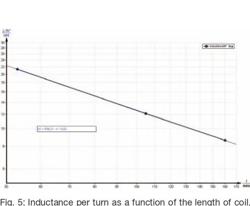
Now that we know that L~ N2, we can demonstrate the rela-tionship between inductance and the length of the coil.
Applying the expression
to the regression line from the measured values in Fig. 5 gives the exponent
C = – 0.82 ± 0.04. ; Ctheo= -0.75
Applying the expression
to the regression line from the measured values in Fig. 6 gives the exponent
D= 1.86 ± 0.07. ; Dtheo= 1.75
The Equation (5) is thus verified within the limits of error.
L
1 300 0.02 0.16 794.65
2 300 0.016 0.16 537.75 3 300 0.013 0.16 373.91 4 200 0.02 0.105 484.38 5 100 0.02 0.053 202.22
6 150 0.013 0.16 93.48
Related topics
Law of inductance, Lenz’s law, self-inductance, solenoids, transformer, oscillatory circuit, resonance, damped oscillation,
logarithmic decrement, Qfactor.
Principle
A square wave voltage of low frequency is applied to oscilla-tory circuits comprising coils and capacitors to produce free, damped oscillations. The values of inductance are calculated from the natural frequencies measured, the capacitance being known.
Equipment
Cobra3 Basic Unit 12150.00 1
Power supply, 12 V 12151.99 2
RS 232 data cable 14602.00 1
Cobra3 Universal writer software 14504.61 1
Cobra3 Function generator module 12111.00 1
Induction coil, 300 turns, dia. 40 mm 11006.01 1
Induction coil, 300 turns, dia. 32 mm 11006.02 1
Induction coil, 300 turns, dia. 25 mm 11006.03 1
Induction coil, 200 turns, dia. 40 mm 11006.04 1
Induction coil, 100 turns, dia. 40 mm 11006.05 1
Induction coil, 150 turns, dia. 25 mm 11006.06 1
Induction coil, 75 turns, dia. 25 mm 11006.07 1
Coil, 1200 turns 06515.01 1
PEK capacitor /case 1/ 470 nF/250 V 39105.20 1
Connection box 06030.23 1
Connecting cord, 250 mm, red 07360.01 1
Connecting cord, 250 mm, blue 07360.04 1
Connecting cord, 500 mm, red 07361.01 2
Connecting cord, 500 mm, blue 07361.04 2
PC, Windows®95 or higher
Tasks
To connect coils of different dimensions (length, radius,
num-ber of turns) with a known capacitance C to form an
oscilla-tory circuit. From the measurements of the natural frequen-cies, to calculate the inductances of the coils and determine the relationships between
1. inductance and number of turns
2. inductance and length
3. inductance and radius.
Set-up and procedure
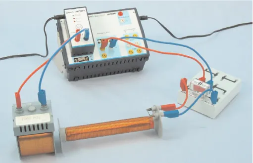
Set up the experiment as shown in Fig. 1 + 2.
A square wave voltage of low frequency (f≈500 Hz) is applied
to the excitation coil L. The sudden change in the magnetic
field induces a voltage in coil L1 and creates a free damped
oscillation in the L1C oscillatory circuit, the frequency fo of
which is measured with the Cobra3 interface.
Coils of different lengthsl, diameters 2rand number of turns
Nare available (Tab. 1). The diameters and lengths are
meas-ured with the vernier caliper and the measuring tape, and the numbers of turns are given.
Tab. 1: Table of coil data
The following coils provide the relationships between induct-ance and radius, length and number of turns that we are in-vestigating:
1.) 3, 6, 7 L = f(N)
2.) 1, 4, 5 L/N2 = f(l)
3.) 1, 2, 3 L = f(r)
As a difference in length also means a difference in the number of turns, the relationship between inductance and number of turns found in Task 1 must also be used to solve Task 2.
Notes
The distance between L1 and L should be as large as possi-ble so that the effect of the excitation coil on the resonant fre-quency can be disregarded. There should be no iron compo-nents in the immediate vicinity of the coils.
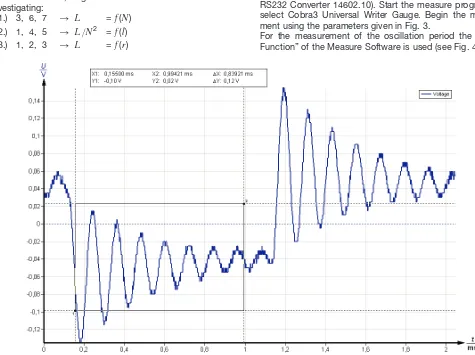
Connect the Cobra3 Basic Unit to the computer port COM1, COM2 or to USB port (for USB computer port use USB to RS232 Converter 14602.10). Start the measure program and select Cobra3 Universal Writer Gauge. Begin the measure-ment using the parameters given in Fig. 3.
For the measurement of the oscillation period the “Survey Function” of the Measure Software is used (see Fig. 4).
Fig. 2: Set-up for inductance measurement. Fig. 3: Measuring parameters.
Fig. 4: Measurement of the oscillation period with the “Survey Function”.
Coil No. N Cat. No.
1 300 40 160 11006.01
2 300 32 160 11006.02
3 300 26 160 11006.03
4 200 40 105 11006.04
5 100 40 53 11006.05
6 150 26 160 11006.06
7 75 26 160 11006.07
l
mm
2r
Fig. 4 shows the rectangular signal and the damped
oscillati-on behind each peak. Determine the frequency f0 of this
dam-ped oszillation,
where Tis the oscillation period.
Theory and evaluation
If a current of strength Iflows through a cylindrical coil
(sole-noid) of lengthl, cross sectional area A= p· r2, and number
of turns N, a magnetic field is set up in the coil. When l>> r
the magnetic field is uniform and the field strength His easy
to calculate:
(1)
The magnetic flux through the coil is given by
' = mo· m· H· A (2)
where mo is the magnetic field constant and m the absolute
permeability of the surrounding medium.
When this flux changes, it induces a voltage between the ends of the coil,
(3)
where
(4)
is the coefficient of self-induction (inductance) of the coil.
Inductivity Equation (4) for the inductance applies only to very
long coils l>> r, with a uniform magnetic field in accordance
with (1).
In practice, the inductance of coils with l> rcan be
calcula-ted with greater accuracy by an approximation formula
The inductance is therefore represented by
(7)
where Ctot.= C+ Ci and
The table 2 shows the theoreticalinductance values of the
used coils calculated according to eq. 5.
Table 2
The table 3 shows the measuredvalues of the oscillation
peri-ods and the corresponding inductance values of the used
coils calculated according to eq. 7. These Lexp values are
plotted in Figs. 5, 6 and 7.
Fig. 5: Inductances of the coils as a function of the number of turns, at constant length and constant radius.
Double logarithmic plotting
1 300 0.02 0.16 794.65
2 300 0.016 0.16 537.75
3 300 0.013 0.16 373.91
4 200 0.02 0.105 484.38
5 100 0.02 0.053 202.22
6 150 0.013 0.16 93.48
Applying the expression
L = A· NB
to the regression line from the measured values in Fig. 5 gives the exponent
B = 1.95±0.04 ; Btheo= 2 (see Eq. 5)
Now that we know that L~ N2, we can demonstrate the
rela-tionship between inductance and the length of the coil.
Applying the expression
to the regression line from the measured values in Fig. 6 gives the exponent
C= -0.82±0.04 ; Ctheo= -0.75
Applying the expression
to the regression line from the measured values in Fig. 7 gives the exponent
D= 1.86 ± 0.07. ; Dtheo= 1.75
The Equation (5) is thus verified within the limits of error.
L
N2A · r D
L N2A · l
C
Fig. 7: Inductance of the coils as a function of the radius, at constant length and number of turns.
Double logarithmic plotting Fig. 6: Inductance per turn as a function of the length of coil,