MECHANICAL DESIGN OF
PRESSURE VESSEL
FOR THREE PHASE SEPARATOR
USING PV ELITE SOFTWARE
Cokorda Prapti Mahandari, Miko Sandi Mechanical Engineering Department, Faculty of
Industrial Technology, Gunadarma University Jl. Margonda Raya 100 Depok 16435
Email: [email protected], [email protected] Phone: 08129585714
ABSTRACT
The safety factor of a pressure vessel is related to both the tensile stress and yield strength for material allowance. ASME Code Section VIII has fully covered these two on the construction code for pressure vessel. This code section addressed mandatory requirement, specific prohibition, and non mandatory guidance for pressure vessel materials, design, fabrication, examination, inspection, testing, certification, and pressure relief. Mechanical design of a horizontal pressure vessel for three phase separator based on this standard had been done incorporating PV Elite software. Analyses were carried out on head, shell, nozzle, and saddle. The input parameters are type of material, pressure, temperature, and diameter and corrosion allowance. Analysis performed the calculations of internal and external pressure, weight of the element, allowable stresses, vessel longitudinal stress check, nozzle check and saddle check.
Keywords: pressure vessel, mechanical design, PV Elite Software
Introduction
Pressure vessels are containers for the containment of pressure either internal or external. This pressure comes from an external source or by the application of heat from a direct or indirect source or any combination of them. The pressure vessels are used to store fluid that may undergo a change of state inside as in case of boiler or it may combine with other reagent as in a chemical plant. Pressure vessels are commonly used in industry to carry both liquid and gases under pressure. The material comprising the vessel is subjected to pressure loading and hence stresses from all direction. The normal stress resulting from this pressure are functions of radius of the elemen under consideration, the shape of the pressure vessel as well as the applied pressure (ASME, 2007).
One of the presure vessel function is as a separator, which separate a mixture of immiscible fluids of different density. Based on the number
of fluid involved, separator is classified into two phase separator and three phase separator refers to the number of streams leaving the vessel and not the inlet fluid stream.
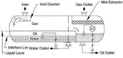
Although most separators are two-phase in design, separating the gas and total liquids, three - phase separator mainly needed in natural gas processing. It separates gas, oil or other liquid hydrocarbons, and free water. Most platforms have a series of production separators, starting with a high-pressure separator, which separates the (HP) gas from the liquids. Liquids are then piped to a medium pressure (MP) separator, which removes more gas and then passes the liquids to a low pressure (LP) separator that removes even more gas and then separates water from the oil (Arnold and Stewart, 1999).
Separators are built in various designs, such as horizontal, vertical or spherical. Vertical separator is commonly used in offshore due to limitation of space. Meanwhile horizontal separator is installed in a plant that space is not considered as barrier. This research reported the design of horizontal three phase separator that typically can be shown as Figure 1 (Taylor and Lucia, 1995).
Figure 1. Three Phase Separator
Process design of three phase separator follows API (American Petroleum Institute) standard criteria. Mathematical model and thermodynamic analysis had been studied extensively (Taylor and Lucia, 1995, Dionne, 1998). Whilst this research merely analysed mechanical design of the three phase separator that basically a pressure vessel. Therefor it is focused on the pressure vessel design.
The pressure vessels must design thoroughly because rupture of pressure vessels causes an explosion that may end in loss of life and property. Research on modelling of leakage of a pressure vessel that contain two phase of fluid has been done. The simultaneous equation was solved using Matlab and the result presented in graphics (Cokorda, 2004). Investigation on the potential of over pressurization of a pressure vessel that carried chemical material had also done (Adkins, 1994). However the first stage to prevent rupture of pressure vessel is designing the pressure vessel with great care.
or dynamic simulation. Design and analysis pressure vessel for static loading and its assessment by Ansys had done (Jimit and Mahavir, 2008) The main feature is to check the behaviour of pressure vessel under fluctuating load include various aspects such as selecting the material based on ASME codes.
This research implements PV Elite software to analysis elements of horizontal pressure vessel for three phase separator. This graphical based software has GUI (Graphical User Interface) that collect model description and the interactive analysis displayed intermediate result conveniently on the same screen.
RESEARCH METHOD
The input design for pressure vessel refers to the data from PT. Sanggar Sarana Baja, one of pressure vessel manufacturer located in Jakarta. This order-based company had a project from one of oil and gas industry to manufacture a horisontal pressure vessel for three phase separator, with the capacity of 9,830 m3, design pressure of 138 bar, design temperature of 65 0C and maximum corrosion allowance of 3 mm. Head diameter is 1.52 m and shell diameter is 1.5 m and length of vessel is 4.5 m. The software was also facilitate accordingly.
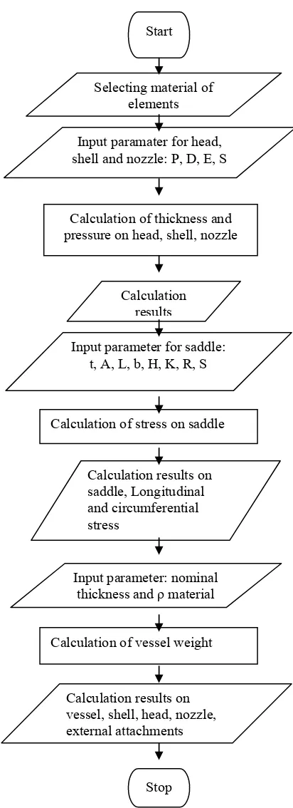
Design procedure followed exactly ASME Code Section VIII. Analysis was carried out only on the following elements of pressure vessel: head, shell, nozzle, and saddle. The step of analyses are illustrated on flow chart as shown on Figure 2. Since the pressure vessel was made by order, then type of material had been determined previously. The pressure vessel constructed easily employ the suitable icon and the parameter design submitted to the input screen. This step was performed on every elements starting from head, shell, nozzle and saddle. All the mathematical equation refer from ASME Code. For example for head calculation, thickness of head is calculated using Equation 1
t = P.R/ (2SE- 0.2P) + CA 1 .Where: t =head thickness, mm
P =pressure, bar R =radius of head, mm S = stress of material, bar E =joint effisiensi
CA =corrosion allowance, mm
Maximum Allowable Working Pressure can be determined using Equation 2
MAWP
2
Figure 2. Research flow chart
Where: ta = allowable thickness, mm.
Allowable thickness depend on the nominal thickness, corrosion allowance, head diameter and shell diameter.
The same equation would appear in the output screen whenever analysis menu was run. The similar step was conducted on different elements such as on shell, nozzle and also saddle. Saddle is
Start
Selecting material of elements
Calculation of thickness and pressure on head, shell, nozzle
Calculation results
Calculation of vessel weight Input parameter: nominal
thickness and ρ material Calculation results on saddle, Longitudinal and circumferential stress
Input parameter for saddle: t, A, L, b, H, K, R, S
Calculation results on vessel, shell, head, nozzle, external attachments Calculation of stress on saddle
Stop
only available on horizontal type of pressure vessel and for vertical one the term is leg. Weight of each element and the total weight of pressure vessel had also calculated.
The output of analysis can be presented in many feature. It can be in the form of table, or export to word processor in the form of final report. Since this research have not completed yet, the output would be presented as they are generated.
RESULT
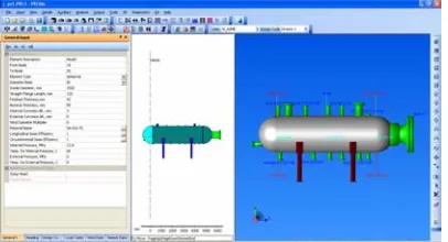
Horizontal pressure vessel is drawn per elements and the icon for each element can be found easily. The input parameter for each element also type in the suitable bar as can been seen on Figure 3 and Figure 4. Once all the elements was connected, the pressure vessel would be as shown on Figure 5.
Figure 3. Head of vessel and the input data screen
Figure 4. Shell of vessel and the input data screen
Figure 5. Pressure vessel and the input screen
Results of elements analysis are shown with equations, substitution and code references.
Results of head analyzes:
Thickness Due to Internal Pressure [Tr] : = (P*(D/2+CA))/(2*S*E-0.2*P) per UG-27 (d) =
(138.062*(1520.0000/2+3.0000))/(2*137.90*1.00 -0.2*138.062)
= 38.5834 + 3.0000 = 41.5834 mm
Max. All.Working Pressure at Given Thickness [MAWP] :
= (2*S*E*(T-Ca))/((D/2+Ca)+0.2*(T-Ca)) per UG-27 (d)
=
(2*137.90*1.00*(39.000))/((1520.000/2+3.000)+ 0.2*(39.000))
= 139.538 - 0.062 = 139.476 bars
Maximal Allowable Pressure, New and Cold [MAPNC] :
= (2*SA*E*T)/(D/2+0.2*T) per UG-27 (d) =2*137.90*1.00*42.0000)/(1520.0000/2+0.2*42. 0000)
= 150.741 bars
Actual Stress at Given Pressure and Thickness : = (P*((D/2+Ca)+0.2*(T-Ca)))/(2*E*(T-Ca)) =(138.062*((1520.000/2+3.000)+0.2*(39.000)))/( 2*1.00*(39.000))
= 136.442 N./mm²
Percent Elongation per UCS-79 (75*tnom/Rf)*(1-Rf/Ro) 4.777 %
Results of shell analyzes:
Thickness Due to Internal Pressure [Tr] :
= (P*(D/2+Ca))/(S*E-0.6*P) per UG-27 (c)(1) = (138.062*(1500.0000/2+3.0000))/(137.90*1.00-0.6*138.062)
= 80.2115 + 3.0000 = 83.2115 mm
Max. All. Working Pressure at Given Thickness [MAWP] :
= (S*E*(T-Ca))/((D/2+Ca)+0.6*(T-Ca)) per UG-27 (c)(1)
=(137.90*1.00*(81.0000))/((1500.0000/2+3.0000 )+0.6*81.0000)
= 139.337 - 0.062 = 139.275 bars
Maximal Allowable Pressure, New and Cold [MAPNC] :
= (SA*E*T)/(D/2+0.6*T) per UG-27 (c)(1) =(137.90*1.00*84.0000)/(1500.0000/2+0.6*84.00 00)
= 144.714 bars
Actual Stress at Given Pressure and Thickness : = (P*((D/2+CA)+0.6*(T-CA)))/(E*(T-CA)) =(138.062*((1500.000/2+3.000)+0.6*(81.000)))/( 1.00*(81.000))
= 136.638 N./mm²
Results of Nozzle analyzes: N1
Reqd thk per ug 37 (a) cylindrical shell, Tr [Int. Press]:
= (P*(D/2+CA))/(S*E-0.6*P) per UG-27 (c)(1) = (138.00*(1500.0000/2+3.0000))/(137*1.00-0.6*138.00)
= 80.1731 mm
Reqd thk per ug 37 (a) nozzle wall, Trn[Int. Press] :
= (P*(D/2+CA))/(S*E-0.6*P) per UG-27 (c)(1) = (138.00*(193.5480/2+3.0000))/(137*1.00-0.6*138.00)
= 10.6231 mm Reinforcement
The Area Available without a pad is Sufficient Reinforcement Area Required for Nozzle [Ar]: = (Dlr*Tr+2*Thk*Tr*(1-fr1)) UG-37(c) = (199.5480*80.1731+2*(72.3900-3.0000)*80.1731*(1-1.0000)) = 159.984 cm²
Area corroded condition: Area in Shell[A1] :
Area in Nozzle Wall[A2] :
= ( 2 * min(Tlnp,ho) ) * ( Thk - Can - Trn ) * fr2
UG-45 Minimum Nozzle Neck Thickness Requirement: [Int. Press.]
Wall Thickness per UG45(a), tra = 13.6231 mm Wall Thickness per UG16(b), tr16b = 4.5875 mm Wall Thickness per UG45(b)(1), trb1 =
83.1731mm
Wall Thickness per UG45(b)(2),trb2 = 3.0 mm Wall Thickness per UG45(b)(3),trb3 = Max(trb1, trb2, tr16b) = 83.1731 mm Std. Wall Pipe per UG45(b)(4),trb4 = 11.3344 mm
Reqd thk per ug 37 (a) spherical head, Tr [Int. Press] :
= (P*(D/2+CA))/(S*E-0.6*P) per UG-27 (c)(1) = (138.00*(1500.0000/2+3.0000))/(137*1.00-0.6*138.00)
= 80.1731 mm
Reqd thk per ug 37 (a) nozzle wall, Trn Int. Press] := Ro * ( Z½ - 1 ) per Appendix 1-2 (a)(1) = 51.641*(1.2224½-1)
= 5.4548 mm
Intermediate Calc. for nozzle/shell Welds Tmin 19.0000 mm
Results of saddle analyzes
Longitudinal bending stress at midspan
= ( 0.25 * Q * L * K.2 / ( pi * R² * ( Ts - Ca ))) = ( 0.25 * 23882 * 4740.00 * -0.4883 ) /( 3.141 * 753.0000 * 753.0000 * ( 84.0000 - 3.0000 ))) = -0.94 N./mm²
Longitudinal bending at saddle
= ( 0.25 * Q * L * K.1 / ( pi * R² * ( Ts - Ca ))) = ( 0.25 * 23882 * 4740.00 * 5.4963 ) /( 3.141 * 753.0000 *753.0000 * ( 84.0000 - 3.0000 ))) = 10.57 N./mm²
Tangential shear in shell near saddle
= Q * K.4 * (( L-H-2A )/( L+H ))/( R*(Ts-Ca)) = 23882 * 1.1707 * (( 4740.00 - 760.00 - 2 * 1554.00 )/( 4740.00 + 760.00 ))/( 753.0000 * ( 84.0000 - 3.0000 ))
= 0.71 N./mm²
Circumferential stress at horn saddle
= -Q/(4*TEM*(SADWTH+1.56*sqrt(R*TCA))) – 12*Q*R*K.7/(L*TEB)
= -23882 /( 4 * 81.0000 * (220.00 + 1.56 * sqrt(753.0000 *81.0000 )))-12.0 * 23882 * 62.75 * 0.0530 / ( 4740.0005 * 6561.0000 )
= -4.80 N./mm²
Circumferential stress at bottom shell
= (Q*( K.9/( TEM9 * WPDWTH ) ) )
= ( 23882 *( 0.7603 /( 106.4000 * 300.000 ) ) ) = -5.58 N./mm²
DISCUSSION
Design of pressure vessel can be finished quickly by applying numerous calculations in software. The drawing process was simpler associated to other software.
CONCLUSION
Mechanical design of pressure vessel for three phase separator had been done using graphical based software. Drawing process was very easy and input parameter can be entered in the same screen. The result fully complied with standard code and had been employed on practical design of pressure vessel.
Research can be explored to take into account other parameters. Selection material referring to ASME standard can also been developed. The behaviors of pressure vessels in case of fluctuating load could be a challenging matter for future research.
REFERENCES
Arnold, K and Stewart, M., 1999, Surface Production Operation: Design of Oil-Handling Systems and Facilities, Gulf Professional Publishing Company, Houston
ASME, 2007, Boiler & Pressure Vessel Code: Rules for Construction of Pressure vessels, (ASME VIII), Division 1, ASME.
Cokorda Prapti Mahandari, 2004, Pemodelan Kebocoran Tangki Tekan Menggunakan Perangkat Lunak Matlab, Proceeding KOMMIT, Universitas Gunadarma, Jakarta,
Dionne, M.M., 1998, “The dynamic simulation of a three phase separator,” Master’s thesis, University of Calgary, Calgary