LAMPIRAN A Program pada mikrokontroler
/******************************************************* This program was created by the
CodeWizardAVR V3.12 Advanced
Project : gelombang Version : Revisi 4 Date : xx/xx/2015 Author : Nisa
Company : Fisika s-1 FMIPA USU 2010 Comments: ganbatte
****************************************************** /#include <mega32a.h
// I2C Bus functions #include <i2c.h> #include <stdlib.h> #include <delay.h> #include <math.h>
// Declare your global variables here
//---// #define DATA_REGISTER_EMPTY (1<<UDRE)
#define DATA_OVERRUN (1<<DOR) // USART Receiver buffer
#define RX_BUFFER_SIZE 8 char rx_buffer[RX_BUFFER_SIZE]; #if RX_BUFFER_SIZE <= 256
unsigned char rx_wr_index=0,rx_rd_index=0; #else
unsigned int rx_wr_index=0,rx_rd_index=0; #endif
#if RX_BUFFER_SIZE < 256 unsigned char rx_counter=0; #else
unsigned int rx_counter=0; #endif
// This flag is set on USART Receiver buffer overflow bit rx_buffer_overflow;
// USART Receiver interrupt service routine interrupt [USART_RXC] void usart_rx_isr(void) {
char status,data; status=UCSRA; data=UDR;
if ((status & (FRAMING_ERROR | PARITY_ERROR | DATA_OVERRUN))==0)
{
#if RX_BUFFER_SIZE == 256
// special case for receiver buffer size=256 if (++rx_counter == 0) rx_buffer_overflow=1; #else
if (rx_wr_index == RX_BUFFER_SIZE) rx_wr_index=0; if (++rx_counter == RX_BUFFER_SIZE)
{
rx_counter=0;
rx_buffer_overflow=1; }
#endif } }
#ifndef _DEBUG_TERMINAL_IO_
// Get a character from the USART Receiver buffer #define _ALTERNATE_GETCHAR_
#pragma used+ char getchar(void) {
char data;
while (rx_counter==0);
data=rx_buffer[rx_rd_index++]; #if RX_BUFFER_SIZE != 256
if (rx_rd_index == RX_BUFFER_SIZE) rx_rd_index=0; #endif
--rx_counter; #asm("sei") return data; }
#pragma used- #endif
// USART Transmitter buffer #define TX_BUFFER_SIZE 8 char tx_buffer[TX_BUFFER_SIZE]; #if TX_BUFFER_SIZE <= 256
unsigned char tx_wr_index=0,tx_rd_index=0; #else
unsigned int tx_wr_index=0,tx_rd_index=0; #endif
#if TX_BUFFER_SIZE < 256 unsigned char tx_counter=0; #else
unsigned int tx_counter=0; #endif
// USART Transmitter interrupt service routine interrupt [USART_TXC] void usart_tx_isr(void) {
if (tx_counter) --tx_counter;
if (tx_rd_index == TX_BUFFER_SIZE) tx_rd_index=0; #endif
} }
#ifndef _DEBUG_TERMINAL_IO_
// Write a character to the USART Transmitter buffer #define _ALTERNATE_PUTCHAR_
#pragma used+ void putchar(char c) {
while (tx_counter == TX_BUFFER_SIZE); #asm("cli")
if (tx_counter || ((UCSRA & DATA_REGISTER_EMPTY)==0)) {
tx_buffer[tx_wr_index++]=c; #if TX_BUFFER_SIZE != 256
if (tx_wr_index == TX_BUFFER_SIZE) tx_wr_index=0; #endif
++tx_counter; }
else UDR=c; #asm("sei") }
// Standard Input/Output functions #include <stdio.h>
//---ADDRESS REGISTER VARIABEL SENSOR---//
#define MPU6050_ADDRESS 0xD0 // Address with end write bit #define MPU6050_RA_XG_OFFS_TC 0x00 //[7] PWR_MODE, [6:1] XG_OFFS_TC, [0] OTP_BNK_VLD
#define MPU6050_RA_YG_OFFS_TC 0x01 //[7] PWR_MODE, [6:1] YG_OFFS_TC, [0] OTP_BNK_VLD
#define MPU6050_RA_ZG_OFFS_TC 0x02 //[7] PWR_MODE, [6:1] ZG_OFFS_TC, [0] OTP_BNK_VLD
#define MPU6050_RA_X_FINE_GAIN 0x03 //[7:0] X_FINE_GAIN #define MPU6050_RA_Y_FINE_GAIN 0x04 //[7:0] Y_FINE_GAIN #define MPU6050_RA_Z_FINE_GAIN 0x05 //[7:0] Z_FINE_GAIN #define MPU6050_RA_SMPLRT_DIV 0x19
#define MPU6050_RA_CONFIG 0x1A
#define MPU6050_RA_GYRO_CONFIG 0x1B #define MPU6050_RA_ACCEL_CONFIG 0x1C #define MPU6050_RA_FF_THR 0x1D
#define MPU6050_RA_FF_DUR 0x1E #define MPU6050_RA_MOT_THR 0x1F #define MPU6050_RA_MOT_DUR 0x20 #define MPU6050_RA_ZRMOT_THR 0x21 #define MPU6050_RA_ZRMOT_DUR 0x22 #define MPU6050_RA_FIFO_EN 0x23
#define MPU6050_RA_EXT_SENS_DATA_16 0x59 #define MPU6050_RA_EXT_SENS_DATA_17 0x5A #define MPU6050_RA_EXT_SENS_DATA_18 0x5B #define MPU6050_RA_EXT_SENS_DATA_19 0x5C #define MPU6050_RA_EXT_SENS_DATA_20 0x5D #define MPU6050_RA_EXT_SENS_DATA_21 0x5E #define MPU6050_RA_EXT_SENS_DATA_22 0x5F #define MPU6050_RA_EXT_SENS_DATA_23 0x60 #define MPU6050_RA_MOT_DETECT_STATUS 0x61 #define MPU6050_RA_I2C_SLV0_DO 0x63
#define MPU6050_RA_I2C_SLV1_DO 0x64 #define MPU6050_RA_I2C_SLV2_DO 0x65 #define MPU6050_RA_I2C_SLV3_DO 0x66
#define MPU6050_RA_I2C_MST_DELAY_CTRL 0x67 #define MPU6050_RA_SIGNAL_PATH_RESET 0x68 #define MPU6050_RA_MOT_DETECT_CTRL 0x69 #define MPU6050_RA_USER_CTRL 0x6A
#define MPU6050_RA_PWR_MGMT_1 0x6B #define MPU6050_RA_PWR_MGMT_2 0x6C #define MPU6050_RA_BANK_SEL 0x6D
#define MPU6050_RA_MEM_START_ADDR 0x6E #define MPU6050_RA_MEM_R_W 0x6F
#define MPU6050_RA_FIFO_R_W 0x74 #define MPU6050_RA_WHO_AM_I 0x75
//---END---/
//---FUNGSI-FUNGSI PADA SENSOR---//
void nulis_i2c(unsigned char alamatt,unsigned char regg, unsigned char dataa) {
i2c_start();
i2c_write(alamatt | 0); i2c_write(regg); i2c_write(dataa); i2c_stop(); delay_ms(10); }
char baca_i2c(unsigned char alamat,unsigned char reg) {
unsigned char baca; i2c_start();
i2c_write(alamat |0); i2c_write(reg); i2c_start();
i2c_write(alamat |1); baca=i2c_read(0); i2c_stop();
}
void tes_i2c() {
unsigned char Datax = 0x00;
do{Datax=baca_i2c(MPU6050_ADDRESS, MPU6050_RA_WHO_AM_I);
if(Datax == 0x68) {
printf("cek berhasil"); }
else {
printf("cek gagal"); }
delay_ms(1000); } while(Datax!=0x68); }
//setelah sesuai dengan register who am i kita lanjut ke setting register : void setup_mpu6050()
{
//f sample ratenya 1k karena DPLF aktif 1000/1+1 = 500Hz
nulis_i2c(MPU6050_ADDRESS,MPU6050_RA_CONFIG,0x03); //Disable gyro self tests, scale of 250 degrees/s
nulis_i2c(MPU6050_ADDRESS, MPU6050_RA_GYRO_CONFIG, 0x00); //Disable accel self tests, scale of +-2g, no DHPF
nulis_i2c(MPU6050_ADDRESS, MPU6050_RA_ACCEL_CONFIG, 0b00000000);
//Freefall threshold of |0mg|
nulis_i2c(MPU6050_ADDRESS, MPU6050_RA_FF_THR, 0x00); //Freefall duration limit of 0
nulis_i2c(MPU6050_ADDRESS, MPU6050_RA_FF_DUR, 0x00); //Motion threshold of 0mg
nulis_i2c(MPU6050_ADDRESS, MPU6050_RA_MOT_THR, 0x00); //Motion duration of 0s
nulis_i2c(MPU6050_ADDRESS, MPU6050_RA_MOT_DUR, 0x00); //Zero motion threshold
nulis_i2c(MPU6050_ADDRESS, MPU6050_RA_ZRMOT_THR, 0x00); //Zero motion duration threshold
nulis_i2c(MPU6050_ADDRESS, MPU6050_RA_ZRMOT_DUR, 0x00); //Disable sensor output to FIFO buffer
nulis_i2c(MPU6050_ADDRESS, MPU6050_RA_FIFO_EN, 0x00); //i2c MST CLOCK 348 kHz divider 23 dari 8Mhz mpu6050 internal clk nulis_i2c(MPU6050_ADDRESS, MPU6050_RA_I2C_MST_CTRL, 0x00); //Setup AUX I2C slaves
nulis_i2c(MPU6050_ADDRESS, MPU6050_RA_I2C_SLV1_ADDR, 0x00); nulis_i2c(MPU6050_ADDRESS, MPU6050_RA_I2C_SLV1_REG, 0x00); nulis_i2c(MPU6050_ADDRESS, MPU6050_RA_I2C_SLV1_CTRL, 0x00); nulis_i2c(MPU6050_ADDRESS, MPU6050_RA_I2C_SLV2_ADDR, 0x00); nulis_i2c(MPU6050_ADDRESS, MPU6050_RA_I2C_SLV2_REG, 0x00); nulis_i2c(MPU6050_ADDRESS, MPU6050_RA_I2C_SLV2_CTRL, 0x00); nulis_i2c(MPU6050_ADDRESS, MPU6050_RA_I2C_SLV3_ADDR, 0x00); nulis_i2c(MPU6050_ADDRESS, MPU6050_RA_I2C_SLV3_REG, 0x00); nulis_i2c(MPU6050_ADDRESS, MPU6050_RA_I2C_SLV3_CTRL, 0x00); nulis_i2c(MPU6050_ADDRESS, MPU6050_RA_I2C_SLV4_ADDR, 0x00); nulis_i2c(MPU6050_ADDRESS, MPU6050_RA_I2C_SLV4_REG, 0x00); nulis_i2c(MPU6050_ADDRESS, MPU6050_RA_I2C_SLV4_DO, 0x00); nulis_i2c(MPU6050_ADDRESS, MPU6050_RA_I2C_SLV4_CTRL, 0x00); nulis_i2c(MPU6050_ADDRESS, MPU6050_RA_I2C_SLV4_DI, 0x00); //MPU6050_RA_I2C_MST_STATUS //Read-only
//Setup INT pin and AUX I2C pass through
nulis_i2c(MPU6050_ADDRESS, MPU6050_RA_INT_PIN_CFG, 0x00); //Enable data ready interrupt
nulis_i2c(MPU6050_ADDRESS, MPU6050_RA_INT_ENABLE, 0x00); //Slave out, dont care
nulis_i2c(MPU6050_ADDRESS, MPU6050_RA_I2C_MST_DELAY_CTRL, 0x00);
//Reset sensor signal paths
nulis_i2c(MPU6050_ADDRESS, MPU6050_RA_SIGNAL_PATH_RESET, 0x00);
//Motion detection control
nulis_i2c(MPU6050_ADDRESS, MPU6050_RA_MOT_DETECT_CTRL, 0x00);
//Disables FIFO, AUX I2C, FIFO and I2C reset bits to 0
nulis_i2c(MPU6050_ADDRESS, MPU6050_RA_USER_CTRL, 0x00); //Sets clock source to gyro reference w/ PLL
nulis_i2c(MPU6050_ADDRESS, MPU6050_RA_PWR_MGMT_1, 0b00000010);
//Controls frequency of wakeups in accel low power mode plus the sensor standby modes
nulis_i2c(MPU6050_ADDRESS, MPU6050_RA_PWR_MGMT_2, 0x00); nulis_i2c(MPU6050_ADDRESS, MPU6050_RA_FIFO_R_W, 0x00); printf("setup done");
delay_ms(1000); }
//setelah menulis register-register ini sensor data sensor siap di akuisisi. pertama akusisi data accelero
//contoh programnya seperti dibawah: void akusisi_accel()
{
axx_yl = baca_i2c(MPU6050_ADDRESS,MPU6050_RA_ACCEL_YOUT_L); axx_zh = baca_i2c(MPU6050_ADDRESS,MPU6050_RA_ACCEL_ZOUT_H); axx_zl = baca_i2c(MPU6050_ADDRESS,MPU6050_RA_ACCEL_ZOUT_L); axx_x = ((axx_xh<<8)|axx_xl)/100;
axx_y = ((axx_yh<<8)|axx_yl)/100; axx_z = ((axx_zh<<8)|axx_zl)/100;
axx_sudut_x =(float) 57.295*atan((float)axx_y/ sqrt(pow((float)axx_z,2)+pow((float)axx_x,2))); axx_sudut_y =(float) 57.295*atan((float)-axx_x/ sqrt(pow((float)axx_z,2)+pow((float)axx_y,2))); axx_sudut_z =(float)
57.295*atan(sqrt(pow((float)axx_x,2)+pow((float)axx_y,2))/(float)axx_z); }
//---END---// void main(void)
{
// Declare your local variables here // Input/Output Ports initialization // Port A initialization
// Function: Bit7=In Bit6=In Bit5=In Bit4=In Bit3=In Bit2=In Bit1=In Bit0=In DDRA=(0<<DDA7) | (0<<DDA6) | (0<<DDA5) | (0<<DDA4) | (0<<DDA3) | (0<<DDA2) | (0<<DDA1) | (0<<DDA0);
// State: Bit7=T Bit6=T Bit5=T Bit4=T Bit3=T Bit2=T Bit1=T Bit0=T PORTA=(0<<PORTA7) | (0<<PORTA6) | (0<<PORTA5) | (0<<PORTA4) | (0<<PORTA3) | (0<<PORTA2) | (0<<PORTA1) | (0<<PORTA0);
// Port B initialization
DDRB=(0<<DDB7) | (0<<DDB6) | (0<<DDB5) | (0<<DDB4) | (0<<DDB3) | (0<<DDB2) | (0<<DDB1) | (0<<DDB0);
// State: Bit7=T Bit6=T Bit5=T Bit4=T Bit3=T Bit2=T Bit1=T Bit0=T PORTB=(0<<PORTB7) | (0<<PORTB6) | (0<<PORTB5) | (0<<PORTB4) | (0<<PORTB3) | (0<<PORTB2) | (0<<PORTB1) | (0<<PORTB0);
// Port C initialization
// Function: Bit7=In Bit6=In Bit5=In Bit4=In Bit3=In Bit2=In Bit1=In Bit0=In DDRC=(0<<DDC7) | (0<<DDC6) | (0<<DDC5) | (0<<DDC4) | (0<<DDC3) | (0<<DDC2) | (0<<DDC1) | (0<<DDC0);
// State: Bit7=T Bit6=T Bit5=T Bit4=T Bit3=T Bit2=T Bit1=T Bit0=T PORTC=(0<<PORTC7) | (0<<PORTC6) | (0<<PORTC5) | (0<<PORTC4) | (0<<PORTC3) | (0<<PORTC2) | (0<<PORTC1) | (0<<PORTC0);
// Port D initialization
// Function: Bit7=In Bit6=In Bit5=In Bit4=In Bit3=In Bit2=In Bit1=In Bit0=In DDRD=(0<<DDD7) | (0<<DDD6) | (0<<DDD5) | (0<<DDD4) | (0<<DDD3) | (0<<DDD2) | (0<<DDD1) | (0<<DDD0);
// State: Bit7=T Bit6=T Bit5=T Bit4=T Bit3=T Bit2=T Bit1=T Bit0=T PORTD=(0<<PORTD7) | (0<<PORTD6) | (0<<PORTD5) | (0<<PORTD4) | (0<<PORTD3) | (0<<PORTD2) | (0<<PORTD1) | (0<<PORTD0);
// Timer/Counter 0 initialization // Clock source: System Clock // Clock value: Timer 0 Stopped // Mode: Normal top=0xFF // OC0 output: Disconnected
TCNT0=0x00; OCR0=0x00;
// Timer/Counter 1 initialization // Clock source: System Clock // Clock value: Timer1 Stopped // Mode: Normal top=0xFFFF // OC1A output: Disconnected // OC1B output: Disconnected // Noise Canceler: Off
// Input Capture on Falling Edge // Timer1 Overflow Interrupt: Off // Input Capture Interrupt: Off // Compare A Match Interrupt: Off // Compare B Match Interrupt: Off
TCCR1A=(0<<COM1A1) | (0<<COM1A0) | (0<<COM1B1) | (0<<COM1B0) | (0<<WGM11) | (0<<WGM10);
TCCR1B=(0<<ICNC1) | (0<<ICES1) | (0<<WGM13) | (0<<WGM12) | (0<<CS12) | (0<<CS11) | (0<<CS10);
// Timer/Counter 2 initialization // Clock source: System Clock // Clock value: Timer2 Stopped // Mode: Normal top=0xFF // OC2 output: Disconnected ASSR=0<<AS2;
TCCR2=(0<<PWM2) | (0<<COM21) | (0<<COM20) | (0<<CTC2) | (0<<CS22) | (0<<CS21) | (0<<CS20);
TCNT2=0x00; OCR2=0x00;
// Timer(s)/Counter(s) Interrupt(s) initialization
TIMSK=(0<<OCIE2) | (0<<TOIE2) | (0<<TICIE1) | (0<<OCIE1A) | (0<<OCIE1B) | (0<<TOIE1) | (0<<OCIE0) | (0<<TOIE0);
// External Interrupt(s) initialization // INT0: Off
// INT1: Off // INT2: Off
MCUCR=(0<<ISC11) | (0<<ISC10) | (0<<ISC01) | (0<<ISC00); MCUCSR=(0<<ISC2);
// USART initialization
// Communication Parameters: 8 Data, 1 Stop, No Parity // USART Receiver: On
UCSRA=(0<<RXC) | (0<<TXC) | (0<<UDRE) | (0<<FE) | (0<<DOR) | (0<<UPE) | (0<<U2X) | (0<<MPCM);
UCSRB=(1<<RXCIE) | (1<<TXCIE) | (0<<UDRIE) | (1<<RXEN) | (1<<TXEN) | (0<<UCSZ2) | (0<<RXB8) | (0<<TXB8);
UCSRC=(1<<URSEL) | (0<<UMSEL) | (0<<UPM1) | (0<<UPM0) | (0<<USBS) | (1<<UCSZ1) | (1<<UCSZ0) | (0<<UCPOL);
UBRRH=0x00; UBRRL=0x47;
// Analog Comparator initialization // Analog Comparator: Off
// The Analog Comparator's positive input is // connected to the AIN0 pin
// The Analog Comparator's negative input is // connected to the AIN1 pin
ACSR=(1<<ACD) | (0<<ACBG) | (0<<ACO) | (0<<ACI) | (0<<ACIE) | (0<<ACIC) | (0<<ACIS1) | (0<<ACIS0);
SFIOR=(0<<ACME);
// ADC initialization // ADC disabled
ADCSRA=(0<<ADEN) | (0<<ADSC) | (0<<ADATE) | (0<<ADIF) | (0<<ADIE) | (0<<ADPS2) | (0<<ADPS1) | (0<<ADPS0);
// SPI initialization // SPI disabled
// TWI initialization // TWI disabled
TWCR=(0<<TWEA) | (0<<TWSTA) | (0<<TWSTO) | (0<<TWEN) | (0<<TWIE);
// Bit-Banged I2C Bus initialization // I2C Port: PORTA
// I2C SDA bit: 0 // I2C SCL bit: 1 // Bit Rate: 100 kHz
// Note: I2C settings are specified in the
// Project|Configure|C Compiler|Libraries|I2C menu. i2c_init
// Global enable interrupts #asm("sei")
tes_i2c();
setup_mpu6050(); while (1)
{
akusisi_accel();
(data_raw*16,384/32000)*9,81;
printf("%dA%dB%dC%dD",axx_x,axx_y,axx_z,); delay_ms(10);
Program tampilan PC dalam Software delphi
unit Unit1;
interface
uses
Windows, Messages, SysUtils, Variants, Classes, Graphics, Controls, Forms, Dialogs, StdCtrls, CPort, DB, ADODB, ExtCtrls, DBCtrls, Grids, DBGrids, RpCon, RpConDS, RpDefine, RpRave, SUIForm, TeEngine, Series, TeeProcs, Chart;
DBNavigator1: TDBNavigator; ADOConnection1: TADOConnection; ADOTable1: TADOTable;
DataSource1: TDataSource; Label6: TLabel;
Label7: TLabel; Timer1: TTimer; Button5: TButton; RvProject1: TRvProject;
RvDataSetConnection1: TRvDataSetConnection; suiForm1: TsuiForm;
Chart1: TChart;
Timer3: TTimer; Button6: TButton;
Series2: TFastLineSeries; Series3: TFastLineSeries; Series4: TFastLineSeries;
procedure Button4Click(Sender: TObject); procedure Button3Click(Sender: TObject); procedure FormDestroy(Sender: TObject);
procedure ComPort1RxChar(Sender: TObject; Count: Integer); procedure Button1Click(Sender: TObject);
procedure Button2Click(Sender: TObject); procedure FormCreate(Sender: TObject); procedure Timer1Timer(Sender: TObject); procedure Timer2Timer(Sender: TObject); procedure Button5Click(Sender: TObject); procedure Timer3Timer(Sender: TObject); procedure Button6Click(Sender: TObject); private
procedure TForm1.Button4Click(Sender: TObject); begin
comport1.ShowSetupDialog; end;
procedure TForm1.Button3Click(Sender: TObject); begin
close; //close aplikasi
end;
procedure TForm1.FormDestroy(Sender: TObject); begin
//jika form langsung ditutup,comport otomatis nutup sendiri if comport1.Connected = true then
begin
comport1.Connected := false; end;
/////////////////////////////////////////////////////////////////////////////////
//////////////////////////INTI PROGRAM/////////////////////////////////////////// /////////////////////////////////////////////////////////////////////////////////
procedure TForm1.ComPort1RxChar(Sender: TObject; Count: Integer); var A, B, C, D, DataA, DataB, DataC, DataD :string;
s :TstringList
D,E,F,DataD,DataE,DataF,,dan seterusnya.. begin
{cari string 'A', jika ketemu string 'A' maka string SEBELUM 'A' atau data murni akan di taruh dilistbox1 dan string 'A' di delimiter(dihapus). data dilistbox1 akan diambil dan ditampilkan ke edit1, begitu berurutan untuk data setelahnya. kok bisa? ya karena nantinya format pengiriman datanya kan untuk misal 4 sensor suhu LM35 adalah
30A40B50C60D jadi dari format itu kan yg dimasukkan ke edit1 adalah 30 aja,sedangkan string pengenal 'A'
masuk ke listbox1 trus dihapus, data sensor berurutan dari A,B,C,D}
//////////////////SENSOR 1 delimiter string 'A'//////////////////////// //////////////////////////////////////////////////////////////////////
repeat begin
comport1.ReadStr(A,1); DataA:=DataA+A; end;
until A='A';
s:=TStringList.Create; s.Delimiter:='A'; s.DelimitedText:=DataA; listbox1.Items:=s; edit1.Text:=listbox1.Items[0 listbox1.Clear;
//////////////////////AKHIR UNTUK SENSOR 1///////////////////////////////
listbox1.Items:=s;
edit2.Text:=listbox1.Items[0]; listbox1.Clear;
//////////////////////AKHIR UNTUK SENSOR 2///////////////////////////////
//////////////////SENSOR 3 delimiter string 'C'//////////////////////// //////////////////////////////////////////////////////////////////////
//////////////////////AKHIR UNTUK SENSOR 3///////////////////////////////
//////////////////SENSOR D delimiter string 'D'//////////////////////// //////////////////////////////////////////////////////////////////////
repeat begin
comport1.ReadStr(D,1); DataD:=DataD+D; end;
until D='D';
s:=TStringList.Create; s.Delimiter:='D'; s.DelimitedText:=DataD; listbox1.Items:=s;
edit4.Text:=listbox1.Items[0]; listbox1.Clear;
//////////////////////AKHIR UNTUK SENSOR 4///////////////////////////////
adotable1.Open; adotable1.Append;
end;
///////////////////////////////////////////////////////////////////////////
//////////////////////////AKHIR INTI PROGRAM/////////////////////////////// ///////////////////////////////////////////////////////////////////////////
procedure TForm1.Button1Click(Sender: TObject); begin
if comport1.Connected = false then comport1.Connected := true;
end;
end;
procedure TForm1.Button2Click(Sender: TObject); begin
if comport1.Connected = true then comport1.Connected := false; timer3.Enabled:=false;
end;
procedure TForm1.FormCreate(Sender: TObject); var alamatdb : WideString;
begin
alamatdb := ExtractFilePath(Application.ExeName) + 'database.mdb'; with ADOConnection1 do begin
Connected := False; LoginPrompt := False; Mode := cmShareDenyNone;
ConnectionString := 'Provider=Microsoft.Jet.OLEDB.4.0;Data Source=' + alamatdb + ';Persist Security Info=False';
end;
ADOConnection1.Connected := True;
ADOtable1.Connection:= ADOConnection1; ADOtable1.TableName:='dataTemperature'; ADOtable1.Active:=true;
Datasource1.DataSet:= ADOTable1; DBGrid1.DataSource:= DataSource1; RvProject1.ProjectFile:='project1.rav' ; form1.Position := poDesktopCenter; listbox1.Visible := false;
label7.Caption:=timetostr(time); end;
procedure TForm1.Timer1Timer(Sender: TObject); begin
label7.Caption:=timetostr(now); end;
procedure TForm1.Timer2Timer(Sender: TObject); begin
label7.Visible:=true; end;
procedure TForm1.Button5Click(Sender: TObject); begin
RvProject1.Execute;
RvProject1.ExecuteReport('project1.rav'); end;
procedure TForm1.Timer3Timer(Sender: TObject); var suhu1,suhu2,suhu3:integer;
suhu4:real; time:string ; begin
suhu1:=strtoint(edit1.Text);
chart1.Series[0].Add(suhu1,time,clgreen); suhu2:=strtoint(edit2.Text);
chart1.Series[1].Add(suhu2,time,cllime); suhu3:=strtoint(edit3.Text);
chart1.Series[2].Add(suhu3,time,clred); suhu4:=strtofloat(edit4.Text);
chart1.Series[3].Add(suhu4,time,clblue); end;
procedure TForm1.Button6Click(Sender: TObject); begin
timer3.Enabled:=true; end;
LAMPIRAN B
Gambar grafik di PC pada sofware delphi7
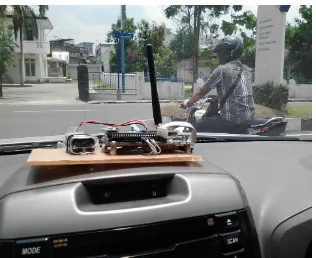
Gambar wireless receiver
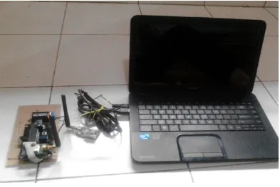
LAMPIRAN C Gambar keseluruhan rangkaian
KYL-Rx