METHODS FOR GEOMETRIC DATA VALIDATION OF 3D CITY MODELS
D. Wagnera,*, N. Alamb, M. Wewetzerc, M. Priesc, V. Coorsb
a University of Tehran, Tehran, Iran – [email protected]
b Hochschule für Technik Stuttgart – University of Applied Sciences, Stuttgart, Germany – [nazmul.alam | volker.coors]@hft-stuttgart.de
c Beuth Hochschule für Technik – University of Applied Sciences, Berlin, Germany – [mwewetzer | pries]@beuth-hochschule.de
Commission VI, WG VI/4
KEY WORDS: Geometry, Validation, CityGML, 3D city model, Requirements, Validation Rules, Tolerances
ABSTRACT:
Geometric quality of 3D city models is crucial for data analysis and simulation tasks, which are part of modern applications of the data (e.g. potential heating energy consumption of city quarters, solar potential, etc.). Geometric quality in these contexts is however a different concept as it is for 2D maps. In the latter case, aspects such as positional or temporal accuracy and correctness represent typical quality metrics of the data. They are defined in ISO 19157 and should be mentioned as part of the metadata.
3D data has a far wider range of aspects which influence their quality, plus the idea of quality itself is application dependent. Thus, concepts for definition of quality are needed, including methods to validate these definitions. Quality on this sense means internal validation and detection of inconsistent or wrong geometry according to a predefined set of rules.
A useful starting point would be to have correct geometry in accordance with ISO 19107. A valid solid should consist of planar faces which touch their neighbours exclusively in defined corner points and edges. No gaps between them are allowed, and the whole feature must be 2-manifold.
In this paper, we present methods to validate common geometric requirements for building geometry. Different checks based on several algorithms have been implemented to validate a set of rules derived from the solid definition mentioned above (e.g. water tightness of the solid or planarity of its polygons), as they were developed for the software tool CityDoctor. The method of each check is specified, with a special focus on the discussion of tolerance values where they are necessary.
The checks include polygon level checks to validate the correctness of each polygon, i.e. closeness of the bounding linear ring and planarity. On the solid level, which is only validated if the polygons have passed validation, correct polygon orientation is checked, after self-intersections outside of defined corner points and edges are detected, among additional criteria. Self-intersection might lead to different results, e.g. intersection points, lines or areas. Depending on the geometric constellation, they might represent gaps between bounding polygons of the solids, overlaps, or violations of the 2-manifoldness.
Not least due to the floating point problem in digital numbers, tolerances must be considered in some algorithms, e.g. planarity and solid self-intersection. Effects of different tolerance values and their handling is discussed; recommendations for suitable values are given.
The goal of the paper is to give a clear understanding of geometric validation in the context of 3D city models. This should also enable the data holder to get a better comprehension of the validation results and their consequences on the deployment fields of the validated data set.
1.1 INTRODUCTION
The relevance of high quality geo data is considered as a key factor for development of down-stream applications and their commercial and public usability. In the past, data quality was mostly referred as accuracy of geo data products and consistency with respect to the real world situation, e.g. (Arsanjani, Barron, Bakillah, & Helbich, 2013), (Zielstra & Zipf, 2010). Researching quality concepts for 3D data extends this definition of data quality to another field, which can be summarized as inherent or internal data quality (cf. Section 3). In this context, data quality can be defined as the grade of compliance with a predefined standard or data model, plus application and user dependent extensions.
One of the most common data models for 3D buildings on a city scale is CityGML, adopted as an OGC standard in version 2.0 in 2010. CityGML includes a semantic model in addition to the GML-based geometric model. Hence validation of consistency of semantics and geometry is a major research field. Prerequisite for investigating consistency issues is the
validation of XML Schema and geometry. For schema validation, commercial tools produce reliable results, however, geometry validation of simple features such as polygons or solids is a more complicated task due to the special characteristics of the geometry model used in CityGML. In this paper, we present algorithms and methods for geometry validation of CityGML models and discuss fundamental questions related with the task.
2. GEOMETRY MODEL OF CITYGML
CityGML 2.0 is based on GML 3.1. The geometry features available in CityGML can be regarded as a profile of the GML features (Kolbe, Gröger, & Plümer, 2005). Some additional restrictions are specified in the standard and have to be considered, such as only planar surfaces may be used, and line strings may have only straight line segments. Solids usually do not have inner shells, although it would be allowed by the standard.
The following definitions of geometric primitives are based on GML 3.1, (Coors & Gröger, 2010) and (OGC, 2006).
Points usually are gml:Point features and consist of coordinate triples or gml:posList features consisting of a list of coordinates where the number of elements can be divided by the coordinate dimension.
outer ring
inner ring
Figure 1: Inner and outer ring sharing one common point.
outer ring
inner ring
Figure 2: Inner and outer ring sharing two points, resulting in a disconnected polygon
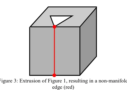
Figure 3: Extrusion of Figure 1, resulting in a non-manifold edge (red)
A gml:LinearRing is a finite sequence of points where the first and last point are identical (closeness) and all other points are different. Edges are implicitly defined as a straight line connection of two neighboring points. Two edges may touch each other only in their start and end points, other points of intersection or touching are not allowed (no self-intersection). A gml:polygon is a surface patch with a planar gml:LinearRing as outer border and one or several inner rings. All rings must be coplanar, the surface of the polygon uses planar interpolation. All LinearRings must not intersect with each other. The inner rings must be located completely inside the boundaries of the outer ring; they may intersect with the outer ring at one point. No inner ring may be located inside another inner ring. Polygons are orientable surfaces where the orientation is determined by the order of the points (usually the outer face is defined counter clockwise). Several connected polygons form a composite surface (a list of orientable surfaces).
There is still some debate about the question if outer and inner rings are allowed to touch in one single point. The problem can be considered solved for 2D polygons (Oosterom, Quak, & Tilssen, 2005). Linear rings describing a polygon may touch in one common point (Coors & Gröger, 2010). Thus, sharing a
single point is normally permitted (Figure 1), whereas sharing two or more points is not allowed (Figure 2).
For 3D features, it is also makes sense to prohibit the connection of an inner ring with the outer ring in more than one point for most scenarios, because the volume of the solid would be no longer connected (Ledoux, 2013),(Kazar, Kothuri, van Oosterom, & Ravada, 2008). Consider the polygon in Figure 1 as the ground surface of a simple LoD1 building. The 3D geometry of this building would be a simple extrusion of the polygon along its normal, as shown in Figure 3. This results in a non-manifold edge (marked with the red line); the edge is shared by 4 polygons (2 from the inner and 2 from the outer ring). Therefore we consider this geometry as invalid.
A solid is the basis for 3D geometry. A solid is delimited by its outer shell, and may have inner shells which represent cavities inside the solid. Each shell of a solid is represented by a composite surface connected in a topological cycle (an object whose boundary is empty). Ongoing discussion (e.g. during the Quality Interoperability Experiment of OGC (Coors & Wagner, 2015)) suggest that inner shells are not used by the CityGML community, which is the reason for neglecting them in the following description.
Volumetric features such as buildings should be modeled as Solid features in CityGML, however, many data sets use MultiSurface geometry instead. In the latter case, a collection of polygons has no meaning, although we can assume in many cases that they are supposed to represent a closed volume when a building is modeled.
3. VALIDATION OF GEOMETRIC FEATURES
According to ISO 19114 data quality can be evaluated with direct or indirect methods, where the direct methods are again subdivided into internal and external (Figure 4).
Figure 4: Classification of data quality evaluation methods (ISO 19114)
External validation is not part of this discussion. Thus the accuracy of point referring to real-world reference points is not considered. The reason for this is that most 3D models are generated from 2D data which should have this kind of quality information as meta data (e.g. cadastral data) or from 3D data with a known accuracy, usually laser point clouds or photogrammetric point clouds. The errors of the source data sets are propagated to the 3D model.
We focus on the inherent correctness and consistency of the geometry, hence validating features such as planarity of polygons or compliance of solids. The validation can be divided into two main groups of checks:
• polygon validation, which is usually applicable for MultiSurface elements. Each polygon is checked individually,
• and solid validation, investigating the spatial combination and topology of a group of polygons for Solid elements.
In both cases, a clear definition of the features concerned and a set of rules which should be adhered to, is necessary. How these can be extracted is shown in the next sections.
3.1 Point Accuracy
Independent of the element used, the accuracy of the points is determined by the number of decimal places. Depending on the generation process of the model, points might have a high number of positions after the decimal point what might result in problems when using floating point computations (Becker, 2006). It makes sense to round coordinate numbers in these cases to a useful amount, e.g. four decimal places. In a data set with Gauss-Krüger coordinates, this results in a point accuracy of 1 mm with a rounding error in the next place.
Moreover, it is important to notice that topological relationships are not stored explicitly. That means, corner points of a 3D geometric feature are stored independently for each of the bounding surfaces, e.g. three times for a cube, each representing the same point. In some cases, there might be differences which cause deficiencies in the model, e.g. it would not be watertight if it is a solid. To avoid such errors resulting from to many decimal places, the same rounding procedures as outlined above is used.
Rounding is preferred to snapping these coordinates to a common position in order to enable detection of modeling defects above a certain threshold (here: 1 mm).
3.2 Polygon Validation
CityGML is based on geometry features of GML 3.1. The definitions below are based on the detailed description in (Coors & Gröger, 2010) which is based on the GML standard, although it implies some difficulties as discussed in Section 2. Validation of polygons according to the definitions above results in the following set of checks.
3.2.1 Minimum number of points
Although seemingly obvious, in some models degenerated LinearRings are contained, e.g. consisting of only three points or less with first and last point identical, which is not sufficient to model an area. Therefore, a LinearRing should consist of at least 4 points. The check counts the number of entries in the sequence. The result is pass/fail including the ID of the LinearRing and the number of points (CP-NUMPOINTS).
3.2.2 Nullarea
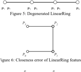
The linear ring delimits an area greater than 0 (Figure 5). Collinearity is checked for all points. The result is pass/fail including the ID of the LinearRing (CP-NULLAREA).
3.2.3 Closeness
A LinearRing must be closed meaning the first and last point of the sequence defining the LinearRing must be identical (Figure 6). The check compares the coordinates of first and last point of the sequence. If the coordinates are not rounded, a tolerance should be defined. The result is pass/fail including the ID of the LinearRing (CP-CLOSE).
3.2.4 Duplicate Points
A LinearRing must not have duplicate points, with exception of start and end point (Figure 7). The check compares the coordinates of all points with each other. If the coordinates are not rounded, a tolerance should be defined. The result is pass/fail including the ID of the LinearRing and the coordinates of duplicate points (CP-DUPPOINT).
Figure 5: Degenerated LinearRing
Figure 6: Closeness error of LinearRing feature
Figure 7: Self Intersection and Duplicate Point errors
3.2.5 Self-Intersection of polygon edges
Two edges can intersect only in one start-/ end-point (Figure 7). Other points of intersection or touching are not allowed (to account for rounding errors or polygons which are not perfectly planar, a small tolerance ε
∈
ℝ is allowed). The check plane to the points of the outer ring and afterwards we calculate the distance of each point of the outer and inner rings to the plane. If the distance of one point exceeds the given tolerance ε, the polygon is marked as non-planar. We adopted the algorithm proposed by (Eberly, 2015) and use least squares where the distance is measured orthogonally to the proposed plane and not in the x-, y- or z-direction of the coordinate system, as illustrated in Figure 8 and Figure 9. Using an approach with an energy function leads to an eigenvalue problem, where the eigenvector of the smallest eigenvalue is the normal vector of the plane we are looking for. Since we are dealing with a real symmetric 3x3 eigensystem, we find the solution by applying the iterative Jacobi eigenvalue algorithm. The position vector of our plane is defined by the average of the points of the outer plane. This seems to be small for an ordinary family home. But this is mainly driven by the self-intersection algorithm for solids which intersects polygons pair wise (cf. section 3.3, Solid Self Intersection) and relies on the projection if these polygons on their fitting plane. There for the polygons should be as planar as possible, to receive reliable results. The value is based on experience and showed to be a fair trade-off between the needs of the self-intersection algorithm and existing real life models. The result is pass/fail including the ID of the LinearRing and the deviation in meters (CP-PLAN).x y
Figure 8: Line fitting done with vertical regression (in y-direction)
x y
Figure 9: Line fitting done with orthogonal regression
Figure 10: Overdone warpage of a quadrangle (blue) and its fitting plane (orange)
3.3 Solid Validation
The performance of the algorithms of solid checks depends on the planarity of the polygons forming the solid. Non-planar surfaces might yield incorrect results under certain conditions. To avoid these problems the tolerance should be as small as possible. However, it is possible to validate a Solid geometry with relatively large tolerance settings to allow only the detection of big folds.
3.3.1 Minimum Number of Polygons
The smallest solid is a tetrahedron, consisting of four triangles. Therefore, the minimum number n of polygons to define a valid solid is four, when they are situated in different planes. The result includes the ID of the erroneous geometry (CS-NUMFACES).
3.3.2 Solid Self-Intersection
The solid self-intersection check is realized by pair wise intersections of polygons of a solid. The planarity of the polygons, as described above, is mandatory, because the problem is transformed into two dimensions to avoid issues with skew warped polygons. Additionally
the shape of a surface of a non-planar outer ring is not defined in CityGML.
Let us suppose we have a triangle and a quadrangle situated as shown in Figure 11. In the first step we calculate the fitting plane of each polygon and project each polygon on its plane, as shown in Figure 12. The advantage of this procedure is that both polygons can only intersect at the intersection straight line
(dashed) of the planes, unless the planes are parallel. We intersect each polygon with the intersection straight separately and get the domain of each intersection, as shown in figure Figure 13 and Figure 14 as green line. By intersecting both domains we retrieve the intersection between both Polygons, see Figure 15.
Figure 11: Initial position. A triangle (polygon 1) intersects with a quadrangle (polygon 2)
Figure 12: Intersection of the fitting planes of both polygons
Figure 13: Intersection of polygon 1 with plane of polygon 2
Figure 14: Intersection of polygon 2 with plane of polygon 1
Figure 15: Combined intersection results of both polygons (intersection marked with red line)
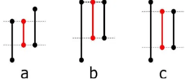
If both polygons are located in the same plane a special treatment is necessary. In this case we intersect each edge of a polygon with the other one and determine if it is located partially or in fully inside the polygon. Merging these information lead to a 2D-domain, reflecting the area of overlapping of both polygons. This can result in a fully embedded polygon intersection type, where one polygon is completely contained in the other one or a simple partially embedded polygon intersection type as shown exemplary in Figure 16. Besides the “normal intersection” as shown in figure Figure 15 and the before mentioned we also take into account if to adjacent polygons intersect at an edge, without sharing the start or end point. We call this type of intersection “embedded edge”. Like embedded polygons we distinguish between partially and fully embedded edges. Figure 17 shows different configuration types for edges and the resulting intersection types. Please note, that the black edges actually lie on top of each other and are “pulled” beside for clarity, which is also indicated by the gray dashed line. The resulting intersection is marked by the red line. Figure 17 shows a partially embedded edge, where both edges don’t share a common point and no black edge is completely covered by the other one. Figure 17 shows a tricky configuration. If both edges share a common point, as indicated by the black dashed line, the intersection type will be set to partially embedded edge. Otherwise it will be set to fully embedded edge. Figure 17 shows fully embedded edge intersection type where the second edge is completely embedded in the first one.
Like the planarity check we are using 0.01m as tolerance to check for coincident points and 0.5° for parallel edges. This also implicates that the length of an intersection interval below 0.01m is treated as intersection point and not line. These tight error bounds result from experience and ensured reliable results especially for the intersection type embedded edge.
The result is pass/fail providing the IDs of the intersecting polygons, the type and the geometric details of the intersection (CS-SELFINT).
Figure 16: Partially embedded polygons intersection type (overlapping intersection in red)
Figure 17: Partially (a, b) and fully (c) embedded intersection type (overlapping intersection in red)
3.3.3 2-Manifoldness
The shell of a solid consists of a composite surface. Therefore it must be 2-manifold. 2-mannifoldness is a complex requirement, validated by several checks.
A valid intersection of two polygons of a solid either contains a common edge, a common point of a linear ring, or is empty. Common edges and points must be elements of both polygons. Any edge of a solid must be incident to exactly two common polygons, otherwise the solid can not be 2-manifold.
Two checks compare all edges of the solid and fails if the number n of incident polygons is not equal to 2. The IDs of the solid and the edge concerned are reported. Two different error types can occur:
• n = 1: There is an outer edge which bounds a hole in the solid geometry, i.e. the solid is not watertight (CS-OUTEREDGE)
• n > 2: Topological error which violates the 2-manifoldness. In Figure 18 there is an edge shared by four polygons (CS-OVERUSEDEDGE).
Figure 18: Topological error caused by an edge with 4 adjacent polygons
In case of a common point incident to several polygons, 2-manifoldness might not exist. This happens when the neighborhood of the point is not topologically equivalent to a disc (Figure 19). The graph GS = (VP,EP) of polygons and edges which are meeting in point pi is connected for all p. Each vertex v
∈
VP represents exactly one polygon which contains p. Two vertices are connected with an edge e∈
EP if the polygons represented by these vertices have a common edge that is bounded by p. If the graph finds more than one loop for connected polygons at a vertex then an umbrella error occurs. The result includes the ID of the solid and the coordinates of the point (CS-UMBRELLA).Figure 19:Topological error caused by a non-manifold point
3.3.4 Consistent orientation
The members of the composite surface forming the shell of a solid must have consistent orientation (cf. Section 2), i.e. their face normals should all be directed towards the inside of the solid or opposite. Consequently, the direction of the edges of two neighboring polygons must be opposite. In Figure 20, polygon A is anti-clockwise oriented whereas polygon B is clockwise oriented. Both polygons are incident to a common edge. The direction of the respective edges is the same which causes an error. If all or most of the edges of a polygon have
wrong orientation then its orientation is wrong. The result includes the ID of the polygon (CS-FACEORIENT).
Figure 20: Inconsistent orientation of polygons
Figure 21: Orientation error of a roof polygon
By definition, normal vectors of the polygons must point towards the outside of the solid (Figure 21). If consistency of the orientation of all polygons is validated, the direction of their normal vectors must be checked. This is done by calculating a normal vector of a polygon and then intersect it with all other polygons of the solid. The number of intersections shall be odd in case it points towards the outside of the solid, even, in case it points towards the inside. The solid has valid orientation when the number of intersection points is odd. In case of error, the ID of the solid is reported (CS-FACEOUT).
3.3.5 Connected component
The shell of a solid must be connected in a topological cycle. This results in a connected geometry for each solid. Disconnected geometries can not be modeled as different part of the same solid (Figure 22). Validation of this requirement is done by generating a graph GS = (VP,EP) of polygons and edges. The result must be a connected graph which contains all polygons and edges of the solid. The check reports the ID of the solid in case of error.
Figure 22: Disconnected solid
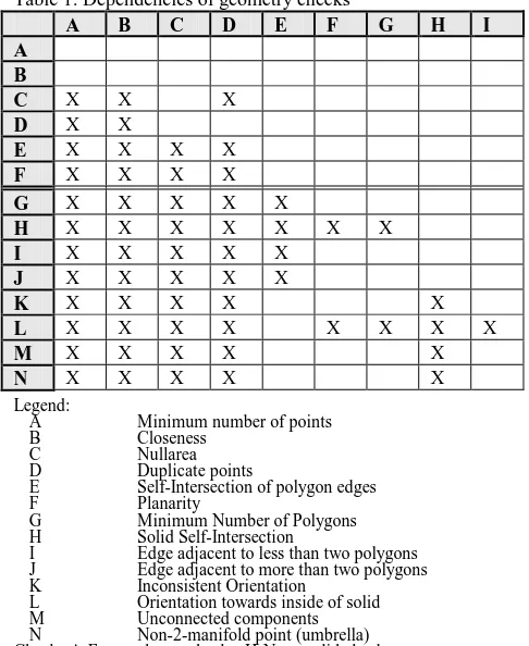
4. HIERARCHY AND DEPENDENCY OF CHECKS Customizing validation rules depends on user requirements. The SIG3D modeling handbook provides a guideline but the user might have own preferences or limitations depending on the application and deployment of the model. Some geometry checks are depending on others (Table 1). Checks in the first column are dependent on those marked with an ‘X’ in the respective row, e.g. the planarity check (F) accepts a geometry feature as input only when it has passed the checks for minimum number of points (A), closeness of the LinearRing (B), nullarea (C) and duplicate points (D) without errors. All polygon checks are independent of the solid checks.
Table 1. Dependencies of geometry checks
A B C D E F G H I
A B
C X X X
D X X
E X X X X
F X X X X
G X X X X X
H X X X X X X X
I X X X X X
J X X X X X
K X X X X X
L X X X X X X X X
M X X X X X
N X X X X X
Legend:
A Minimum number of points
B Closeness
C Nullarea
D Duplicate points
E Self-Intersection of polygon edges
F Planarity
G Minimum Number of Polygons
H Solid Self-Intersection
I Edge adjacent to less than two polygons
J Edge adjacent to more than two polygons
K Inconsistent Orientation
L Orientation towards inside of solid
M Unconnected components
N Non-2-manifold point (umbrella)
Checks A-F are polygon checks, H-N are solid checks
Solid checks are generally performed only for Solid geometries and are only executed when all polygons have a minimum number of four points, are bounded by closed LinearRings without duplicate points, and have an area greater than zero. Planarity is only required for solid self-intersection and determination of correct orientation of all polygons.
MultiSurface geometries can also be checked with the solid checks, if required. This might be helpful in situations where real-world solids have been modeled as MultiSurface
geometries but their solid characteristics is requested for further analysis.
5. CONCLUSION AND OUTLOOK
Geometry definitions are given by standards such as ISO 19107 and GML. Their interpretation for 3D geometry is not unambiguous. Consequently, rules for valid 3D geometries may differ along with user requirements.
Validation of these rules should be done by a modularized approach, where for each restriction one or more check routines are applied. As the definition of 3D geometries is not unambiguous, a suggestion for solid geometry in CityGML models is discussed, where we recommend to prohibit common points of inner and outer rings of a polygon.
Based on this, we describe a set of basics checks. These checks can be combined to satisfy different users’ needs and enable testing of complex requirements such as water-tightness of solids. Besides the basic methods used, we point out the importance of tolerances during the validation process as well as the dependency of some checks on other lower level checks. The set of checks presented above for geometry validation of CityGML models is implemented in the software package CityDoctor (Wewetzer et al., 2013) in JAVA and C++ as proof of concept. Tests on real-world data sets and on synthetic models have been done extensively, latest during the CityGML Quality Interoperability Experiment of OGC (Coors & Wagner, 2015), and showed that general requirements for 3D city models can be validated with this approach.
The success of the strategy was confirmed in comparison with other approaches for geometric validation. Future development should focus on validation of semantic features and the coherency of semantics and geometry.
ACKNOWLEDGEMENTS
Special thanks to Shelly and David Eberly of Geometric Tools, for sharing and offering their knowledge about least squares fitting.
The project CityDoctor was funded by German Ministery for Education and Research (BMBF) and performed as a joint research project of University of Applied Sciences Stuttgart (HFT) and Beuth Hochschule für Technik Berlin.
REFERENCES
Arsanjani, J. J., Barron, C., Bakillah, M., & Helbich, M. (2013). Assessing the Quality of OpenStreetMap Contributors together with their Contributions. Proceedings of the AGILE. http://www.agile-online.org/Conference_Paper/CDs/agile_2013 /Short_Papers/SP_S4.2_Arsanjani.pdf
Becker, P. (2006). Errors in Floating-point Calculations. http://petebecker.com/js/js200007.html (27. Sep 2015)
Coors, V., & Gröger, G. (2010). Handbuch für die Modellierung von 3D Objekten - Teil 1: Grundlagen (Regeln für valide GML Geometrie-Elemente in CityGML).
SIG3D Quality Wiki.
http://wiki.quality.sig3d.org/index.php/Handbuch_f%C3%BCr_ die_Modellierung_von_3D_Objekten_-_Teil_1:_Grundlagen_( Regeln_f%C3%BCr_valide_GML_Geometrie-Elemente_in_Cit yGML) (27. Sep 2015)
Coors, V., & Wagner, D. (2015). CityGML Quality Interoperability Experiment des OGC. Publikationen der Deutschen Gesellschaft für Photogrammetrie, Fernerkundung und Geoinformation e.V., 24, Köln, Germany.
Eberly, D. (2015). Geometric Tools.
http://www.geometrictools.com/Documentation/LeastSquaresFi tting.pdf (27. Sep 2015)
Kazar, B. M., Kothuri, R., van Oosterom, P., & Ravada, S. (2008). On valid and invalid three-dimensional geometries. Advances in 3D geoinformation systems, pp. 19–46. Springer. http://link.springer.com/chapter/10.1007/978-3-540-72135-2_2 (27. Sep 2015)
Kolbe, T. H., Gröger, G., & Plümer, L. (2005). CityGML: Interoperable access to 3D city models. Geo-information for disaster management, pp. 883–899, Springer.
Ledoux, H. (2013). On the validation of solids represented with the international standards for geographic information. Computer-Aided Civil and Infrastructure Engineering, 28(9), 693–706.
OGC (2006). OpenGIS implementation specification for geographic information — simple feature access. Open Geospatial Consortium.
Oosterom, P., Quak, W., & Tilssen, T. (2005). About Invalid, Valid and Clean Polygons. P. F. Fisher (Ed.) Developments in Spatial Data Handling (Vol. Part 1, pp. 1–16). Leicester, UK: Springer Berlin Heidelberg.
Wewetzer, M., Falkenhausen, J., Wagner, D., Alam, M. N., Pries, M., Coors, V., & Fischer, J. (2013). Verbundprojekt CityDoctor - Entwicklung von Methoden und Metriken zum Qualitätsmanagement virtueller Stadtmodelle. Forschungsbericht 2012 - Angewandte Forschung zur Stadt der Zukunft, pp. 15–21. Berlin, Logos Verlag.
Zielstra, D., & Zipf, A. (2010). A comparative study of proprietary geodata and volunteered geographic information for Germany. 13th AGILE international conference on geographic
information science,
http://agile2010.dsi.uminho.pt/pen/shortpapers_pdf/142_doc.pd f (27. Sep 2015)