Open Geospatial Consortium Inc.
Date: 2007-08-02
Reference number of this document: OGC®07-014r3
Version:1.0
Category: OpenGIS® Implementation Specification
Editor: Ingo Simonis, University of Muenster
Change Request Editor: Phillip C. Dibner, Ecosystem Associates
OpenGIS
®Sensor Planning Service Implementation
Specification
Copyright © 2007 Open Geospatial Consortium, Inc. All Rights Reserved.
To obtain additional rights of use, visit http://www.opengeospatial.org/legal/
Notice
This document is an official, member approved, OGC Standard.
Recipients of this document are invited to submit, with their comments, notification of any relevant patent rights of which they are aware and to provide supporting documentation.
Document type: OpenGIS® Implementation Specification Document subtype: Interface
Document stage: Adopted
Contents
Pagei. Preface... ix
ii. Document terms and definitions ... ix
iii. Submitting organizations ... ix
iv. Document contributor contact points...x
v. Revision history ...x
vi. Changes to the OGC Abstract Specification... xi
vii. Future work... xi
Volatility of Service Descriptions... xi
Role-Based Authentication and Control (RBAC)... xii
Foreword ... xiii
Introduction... xiv
1 Scope...15
2 Conformance...15
3 Normative references ...15
4 Terms and definitions ...16
4.1 asset ...16
4.2 asset management system...16
4.3 collection ...16
4.4 requirement...16
5 Conventions ...16
5.1 Abbreviated terms ...16
5.2 UML notation ...17
5.3 XMLSpy notation...17
5.3.1 Element ...17
5.3.2 Optional Element ...17
5.3.3 Recurring Element ...17
5.3.4 Sequence Connector...18
5.3.5 Choice Connector...18
5.3.6 Definition with Complex Type ...18
5.3.7 Complex Type...19
5.4 Used parts of other documents ...20
5.5 Platform-neutral and platform-specific specifications ...20
6 SPS overview ...20
6.1 Introduction ...20
6.2 Collection Management ...21
6.2.1 Requirements Management ...21
6.2.2 Mission Management...22
6.2.3 Asset Management...22
6.3 Collection Management Process ...22
7 Concept of Operations ...23
7.1 Existing System Functionality...23
7.1.1 RM support ...23
7.1.2 MM support ...24
7.1.3 AM support ...24
7.2 Making Existing Functionality Interoperable...24
7.3 Interacting Workflows...25
7.4 Simulation ...25
7.4.1 Basic concepts...25
7.4.2 Integration into Web Services...28
8 Transactions ...28
8.1 Short Term Transactions ...29
8.2 Long Term Transactions ...29
9 SPS Parameters: Internal and external representation ...32
10 SPS Operations ...33
10.1 SPS Operation Overview...33
10.2 SPS Operations Usage...35
11 Shared aspects...39
11.1 Introduction ...39
11.2 Shared operation parameters ...39
11.2.1 InputDescriptor ...39
11.2.2 InputParameter...41
11.2.3 NotificationTarget...42
11.3 Operation request encoding...43
12 GetCapabilities operation (mandatory)...43
12.1 Introduction ...43
12.2 Operation request ...44
12.3 GetCapabilities operation response ...46
12.3.1 Normal response ...46
12.3.2 OperationsMetadata section standard contents...47
12.3.3 Contents section ...48
12.3.4 Capabilities document XML encoding ...50
12.3.5 Capabilities document example ...53
12.3.6 Exceptions...53
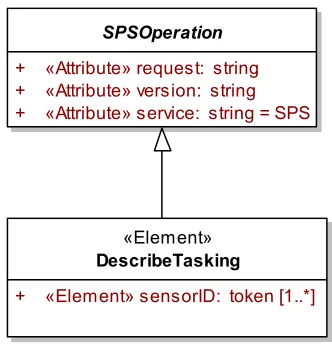
13 DescribeTasking operation (mandatory)...54
13.1 Introduction ...54
13.2 DescribeTasking operation request ...55
13.2.1 DescribeTasking request parameters ...55
13.2.2 DescribeTasking request KVP encoding ...55
13.2.3 DescribeTasking request XML encoding ...55
13.3 DescribeTasking operation response...56
13.3.1 Normal response parameters...57
13.3.2 Normal response XML encoding...58
13.3.3 DescribeTasking response example...58
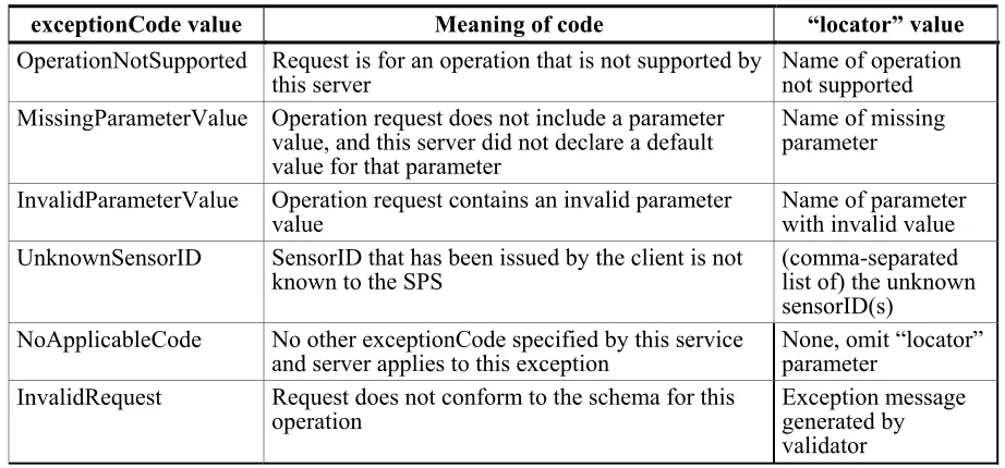
13.3.4 DescribeTasking exceptions ...58
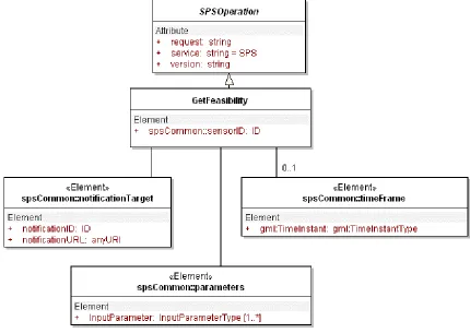
14 GetFeasibility operation (optional) ...59
14.1 Introduction ...59
14.2 GetFeasibility operation ...59
14.2.1 GetFeasibility operation parameters ...60
14.2.2 GetFeasibility request KVP encoding...61
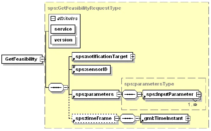
14.2.3 GetFeasibility request XML encoding...61
14.3 GetFeasibility operation response ...62
14.3.1 Normal response parameters...62
14.3.2 Normal response XML encoding...65
14.3.3 GetFeasibility response example ...65
14.3.4 GetFeasibility exceptions...65
15 Submit operation (mandatory) ...67
15.1 Introduction ...67
15.2 Submit operation request...67
15.2.1 Submit request parameters...68
15.2.2 Submit request KVP encoding...69
15.2.3 Submit request XML encoding...70
15.3 Submit operation response ...70
15.3.1 Normal response parameters...70
15.3.2 Normal response XML encoding...73
15.3.3 Submit response example ...73
15.3.4 SubmitRequestResponse exceptions...74
16 GetStatus operation (optional) ...75
16.1 Introduction ...75
16.2 GetStatus operation request...75
16.2.1 GetStatus request parameters...76
16.2.2 GetStatus request KVP encoding...76
16.2.3 GetStatus request XML encoding...77
16.3 GetStatus operation response ...77
16.3.1 Normal response parameters...77
16.3.2 Normal response XML encoding...79
16.3.3 GetStatus response example ...79
16.3.4 GetStatus exceptions...80
17 Upate operation (optional) ...81
17.1 Introduction ...81
17.2 Upate operation request...81
17.2.1 Upate request parameters...82
17.2.2 Upate request KVP encoding...83
17.2.3 Upate request XML encoding...83
17.3 Upate operation response ...84
17.3.1 Normal response parameters...84
17.3.2 Normal response XML encoding...85
17.3.3 Upate response example ...85
17.3.4 Upate exceptions...85
18 Cancel operation (optional)...87
18.1 Introduction ...87
18.2 Cancel operation request ...87
18.2.1 Cancel request parameters ...87
18.2.2 Cancel request KVP encoding ...88
18.2.3 Cancel request XML encoding ...88
18.3 Cancel operation response...89
18.3.1 Normal response parameters...89
18.3.2 Normal response XML encoding...90
18.3.3 Cancel response example...90
18.3.4 Cancel exceptions ...90
19 DescribeResultAccess operation (mandatory)...91
19.1 Introduction ...91
19.2 DescribeResultAccess operation ...91
19.2.1 DescribeResultAccess request parameters...92
19.2.2 DescribeResultAccess request KVP encoding...92
19.2.3 DescribeResultAccess request XML encoding...92
19.3 DescribeResultAccess operation response ...93
19.3.1 Normal response parameters...93
19.3.2 Normal response XML encoding...94
19.3.3 DescribeResultAccess response example ...94
19.3.4 DescribeResultAccess exceptions...95
20 SPS – running example...96
Annex A (normative) Abstract test suite ...114
A.1 General ...114
Annex B (normative) XML Schema Documents...115
B.1 spsAll.xsd ...117
B.2 spsCancelRequest.xsd ...118
B.4 spsCommon.xsd ...120
B.5 spsContents.xsd ...125
B.6 spsDescribeResultAccessRequest.xsd...129
B.7 spsDescribeResultAccessRequestResponse.xsd ...130
B.8 spsDescribeTaskingRequest.xsd ...132
B.9 spsDescribeTaskingRequestResponse.xsd ...133
B.10 spsGetCapabilities.xsd ...134
B.11 spsGetFeasibilityRequest.xsd...136
B.17 spsUpdateRequest.xsd...143
B.18 spsUpdateRequestResponse.xsd...143
B.19 spsMessageSchema.xsd...144
B.20 spsTaskMessageDictionary.xsd ...146
Annex C (informative) UML model ...148
C.1 Introduction ...148
Annex D (informative) Example XML documents ...149
D.1 Introduction ...149
D.2 GetCapabilitiesRequestResponse ...149
Annex E (informative) The ACTM : An Example Task Message Definition...152
E.1 Introduction ...152
E.2 The ACTM Data Dictionary...152
E.3 An outline of the ACTM XML Schema...163
E.4 The ACTM XML Schema...166
Figures
Page Figure 1: Models and Simulation, according to [9], modified ... 26Figure 2: Taxonomy of conventional simulation methods, according to [10]. ... 27
Figure 3: Protocol layers... 29
Figure 4: Simplified sequence diagram in UML notation showing a long term transactions using additional OGC Web services (non OGC specified elements in grey) ... 32
Figure 5: ACTM schema in XMLSpy representation... 33
Figure 6: SPS interface UML diagram... 35
Figure 7: Annotated sequence of the usual steps occurring to submit a task (UML notation) ... 38
Figure 8: Annotated sequence showing the update and describeResultAccess operations in UML notation ... 38
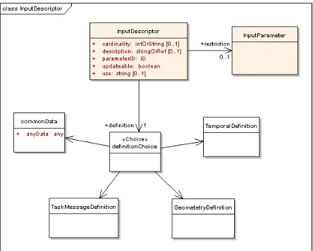
Figure 9: InputDescriptor in UML notation... 40
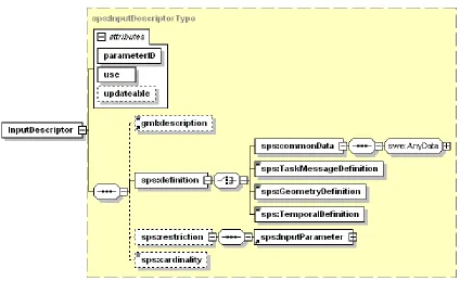
Figure 10: InputDescriptor Element in XMLSpy notation ... 41
Figure 11: InputParameter in UML notation... 42
Figure 12: InputParameter in XMLSpy notation ... 42
Figure 13: notificationTarget parameter in UML notation... 43
Figure 14: notificationTarget parameter in XMLSpy notation ... 43
Figure 15: GetCapabilities request in UML notation (normative) ... 45
Figure 16: GetCapabilitiesRequest in XMLSpy notation (informative) ... 46
Figure 17: contens section in UML notation (normative), further constraints apply ... 49
Figure 18: contents section in XMLSpy notation (informative)... 50
Figure 19: GetCapabilitiesRequestResponse in UML notation (normative) ... 51
Figure 20: GetCapabilitiesRequestResponse in XMLSpy notation (informative) ... 52
Figure 21: GCRR Contents-section in XMLSpy notation ... 53
Figure 22: DescribeTasking in UML notation ... 54
Figure 23: DescribeTasking in UML notation ... 56
Figure 24: DescribeTakingRequest in XMLSpy notation ... 56
Figure 25: DescribeTaskingRequestResponse in UML notation ... 57
Figure 26: DescribeTaskingRequestResponse in XMLSpy notation... 57
Figure 27: GetFeasibilityRequest in UML notation ... 59
Figure 28: GFR in XMLSpy notation... 60
Figure 29: GetFeasibilityRequestResponse in UML notation ... 63
Figure 30: GFRR in XMLSpy notation... 64
Figure 31: Submit in UML notation ... 67
Figure 32: Submit in XMLSpy notation... 68
Figure 33: SubmitRequestResponse parameter in UML notation... 71
Figure 34: SubmitRequestResponse parameter in XMLSpy notation ... 72
Figure 35: GetStatus operation parameters in UML notation... 75
Figure 36: GetStatus operation parameters in XMLSpy notation ... 75
Figure 37: GetStatusRequestResponse parameters in UML notation... 77
Figure 38: GSRR parameters in XMLSpy notation... 78
Figure 39: Upate in UML notation ... 81
Figure 40: UpdateRequest in XMLSpy notation ... 82
Figure 41: UpdateRequestResponse in UML notation ... 84
Figure 42: UpdateRequestResponse in XMLSpy notation ... 84
Figure 43: Cancel in UML notation... 87
Figure 44: Cancel in XMLSpy notation ... 87
Figure 45: CancelRequestResponse in UML notation ... 89
Figure 46: CancelRequestResponse in XMLSpy notation... 89
Figure 47: DescribeResultAccess request in UML notation ... 91
Figure 48: DescribeResultAccess in XMLSpy notation ... 91
Figure 49: DescribeResultAccessRequestResponse in UML notation (Note: add an optional “request” element of type anyType to the service element.) ... 93
Figure 50: DescribeResultAccessRequestResponse in XMLSpy notation ... 94
i. Preface
The OpenGIS Sensor Planning Service (SPS) Implementation Specification is designed to enable an interoperable service by which a client can determine collection feasibility for a desired set of collection requests for one or more sensors/platforms, or a client may submit collection requests directly to these sensors/platforms. Specifically, the document specifies interfaces for requesting information describing the capabilities of a SPS for determining the feasibility of an intended sensor planning request, for submitting such a request, for inquiring about the status of such a request, for updating or cancelling such a request, and for requesting information about further OGC Web services that provide access to the data collected by the requested task.
Suggested additions, changes, and comments on this report are welcome and encouraged. Such suggestions may be submitted by email message or by making suggested changes in an edited copy of this document.
The changes made in this document version, relative to the previous version, are tracked by Microsoft Word, and can be viewed if desired. If you choose to submit suggested changes by editing this document, please first accept all the current changes, and then make your suggested changes with change tracking on.
ii.
Document terms and definitions
This document uses the specification terms defined in Subclause 5.3 of [OGC 05-008], which is based on the ISO/IEC Directives, Part 2, Rules for the structure and drafting of International Standards. In particular, the word “shall” (not “must”) is the verb form used to indicate a requirement to be strictly followed to conform to this specification
iii. Submitting
organizations
The following organizations submitted this document to the Open Geospatial Consortium Inc.
University of Muenster
iv.
Document contributor contact points
All questions regarding this document should be directed to the editor. Additional contributors are listed below:
Name Organization Alexander Walkowksi University of Muenster
Alexandre Robin UAH
Ingo Simonis (editor) University of Muenster Jeff Lansing Polexis, Inc.
Jim Greenwood SeiCorp, Inc
Johannes Echterhoff University of Muenster John Davidson Image Matters
Mark Priest 3eti
Mike Botts UAH
Phillip Dibner (CR Editor) Ecosystem Associates
Simon Cox CSIRO
v. Revision
history
Date Release Editor Primary
clauses modified
Description
2003-01-14 0.0.6 Jeff Lansing initial version initial version; deprecated
2005-10-20 0.0.30 Ingo Simonis new version 0.0.6 deprecated. All operations and information model changed.
2005-12-02 r1 Ingo Simonis all adapted to schema changes 2006-02-06 r2 Johannes
Echterhoff
all adapted to final schema changes. Examples new. Version intended to be part of RFC. 2006-02-09 r2 Phillip
Dibner
Future Work content added
2006-02-12 r2 Ingo Simonis all latest adaptions. 2007-02-02 0.1.5 of
all updates to schema and material that depends on it, for compatibility with sweCommon 1.0; also changes resulting from comments to the RFC.
2007-08-02 R3 Carl Reed various Ready for posting as an OGC Standard
vi.
Changes to the OGC Abstract Specification
The OpenGIS® Abstract Specification does not require changes to accommodate the technical contents of this document.
vii. Future
work
This SPS specification provides information concerning content and encoding of the parameter data that has to be provided in order to task a sensor. Though it defines
mechanisms to restrict possible instance documents, e.g. the integer data of the parameter
speed has to be within the interval [0,100], there is currently no mechanism to restrict parameters or the possible parameter values in dependence on other parameters. Example: You must deliver the parameter A if parameter B is greater than 50 and
parameter C is before ten days from now'. Such a feature will remain for future versions. Future work must also incorporate two notions that are not included in the current revision of this document. Neither of these issues applies solely to sensor systems, and the solutions may lie partly or wholly within other domains defined by the OGC
architecture. Nonetheless, given their relevance to sensors, we discuss them here.
Volatility of Service Descriptions
The first issue is volatility of descriptive metadata that applies to the sensor, to its platform, or to its area of service. Many sensors can assume a variety of configurations, and the same is true of sensor platforms. An SPS Capabilities document, possibly combined with a SensorML document, might provide a detailed description of a sensing device or its platform at one moment that is not valid at another time. If such documents were saved in an online catalogue, and retrieved when it was no longer valid, users might find that they are unsuccessful in requesting the acquisition of data that the service description documents claim is available. Worse yet, the user might be able to request a collection that doesn't conform to the advertised specifications, leading to wasted expenses or incorrect interpretation. The problem could be even more severe, or even dangerous, in the case of a reconfigurable airborne platform.
The issue of volatile configuration is not limited to sensor systems. Data services like WMS, WFS, and WCS may be quite dynamic. The area they cover and the datatypes they provide may change with time. There needs to be a mechanism that prevents this type of confusion, either by preventing volatile information from being cached by OGC catalogs, or by including some metadata in the service description documents that tells whether or for how long the documents are valid.
Clearly, this is a generic issue for the OGC architecture. However, it is particularly relevant to sensors and the sensor web, especially where configurable or mobile sensors
are concerned. It must be addressed, as a matter of high priority, in future work.
Role-Based Authentication and Control (RBAC)
The second requirement involves the very real need in practical systems for a clear definition of the roles played by different users of the sensor system, and the
corresponding permissions that accrue to each of them. The individual who wishes to acquire data from a sensor is not necessarily the same person who configures or enables the sensor to operate in a particular mode.
For example, a multispectral scanner may have the capability to collect radiometric data from ten or more bands in the electromagnetic spectrum, but the image processing system or data transmission circuitry associated with that scanner may only have the capacity to accommodate three of those bands at a single time. In general, a request to collect an image using three particular bands will not automatically reconfigure the scanner package so that those three bands are routed to the processing or data transmission subsystems. This task must be done by someone who has access to and familiarity with the sensor configuration controls, not by the person who has requested the image.
A more dramatic example applies to sensor payloads carried by occupied or unoccupied airborne systems. The individuals who request imagery from a certain location on the earth's surface, or who configure the sensor payload, are likely not the same people who fly the aircraft, or even who develop and file the aircraft's flight plan.
These examples point to the need for Role-Based Authentication and Configuration (RBAC) in the operational management of sensing devices and control systems. Some of this technology might arise from the Geographic Digital Rights Management (GeoDRM) experimentation that was performed concurrently with this specification. Whether or not this turns out to be the case, future work on the SPS must address RBAC for sensor systems.
Foreword
The Sensor Planning Service is part of the OGC Sensor Web Enablement document suite. This document includes four annexes; Annexes A and B are normative, and Annexes C and D are informative.
Attention is drawn to the possibility that some of the elements of this document may be the subject of patent rights. The Open Geospatial Consortium Inc. shall not be held responsible for identifying any or all such patent rights.
Recipients of this document are requested to submit, with their comments, notification of any relevant patent claims or other intellectual property rights of which they may be aware that might be infringed by any implementation of the specification set forth in this document.
Introduction
The Sensor Planning Service (SPS) provides a standard interface to collection assets (i.e., sensors, and other information gathering assets) and to the support systems that surround them. Not only must different kinds of assets with differing capabilities be supported, but also different kinds of request processing systems, which may or may not provide access to the different stages of planning, scheduling, tasking, collection, processing, archiving, and distribution of requests and the resulting observation data and information that is the result of the requests. The SPS is designed to be flexible enough to handle such a wide variety of configurations.
If you want get a quick overview of SPS in conjunction with some additional informative notes, please consider reading section 20, SPS running example, first.
OpenGIS
®Sensor Planning Service Implementation
Specification
1 Scope
This OpenGIS® document specifies interfaces for requesting information describing the capabilities of a Sensor Planning Service, for determining the feasibility of an intended sensor planning request, for submitting such a request, for inquiring about the status of such a request, for updating or cancelling such a request, and for requesting information about further OGC Web services that provide access to the data collected by the
requested task.
2 Conformance
Conformance with this specification shall be checked using all the relevant tests specified in Annex A (normative).
3 Normative references
The following normative documents contain provisions that, through reference in this text, constitute provisions of this document. For dated references, subsequent
amendments to, or revisions of, any of these publications do not apply. For undated references, the latest edition of the normative document referred to applies.
ISO 19105:2000, Geographic information — Conformance and Testing
OGC 05-008, OpenGIS® Web Services Common Specification
This OWS Common Specification contains a list of normative references that are also applicable to this Implementation Specification.
OGC 05-114 OpenGIS® Web Notification Service OGC 05-090 SWE Architecture
OGC 05-088 SOS OGC 05-087 O&M OGC 05-086 SensorML
OGC 04-092r4 GML
In addition to this document, this specification includes several normative XML Schema Document files as specified in Annex B.
4 Terms and definitions
For the purposes of this specification, the definitions specified in Clause 4 of the OWS Common Implementation Specification [OGC 05-008] shall apply. In addition, the following terms and definitions apply.
4.1 asset
synonyms: sensor, simulation
an available means. For the SPS, an available means of collecting information.
4.2 asset management system
synonyms: acquisition system, asset support system
a system for controlling the effective utilization of an asset 4.3 collection
process sense (default for this document): the act of gathering something together result sense: an aggregation of the results of one or more collection processes. 4.4 requirement
something that is necessary in advance
5 Conventions
5.1 Abbreviated terms
Most of the abbreviated terms listed in Subclause 5.1 of the OWS Common
Implementation Specification [OGC 05-008] apply to this document, plus the following abbreviated terms.
SOS Sensor Observation Service WNS Web Notification Service SAS Sensor Alert Service SWE Sensor Web Enablement O&M Observation and Measurement SensorML Sensor Model Language
TML Transducer Markup Language
5.2 UML notation
Most diagrams that appear in this specification are presented using the Unified Modeling Language (UML) static structure diagram, as described in Subclause 5.2 of [OGC 05-008].
5.3 XMLSpy notation
Most diagrams that appear in this specification are presented using an XML schema notation defined by the XMLSpy1 product and described in this subclause. XML schema
diagrams are for informative use only though they shall reflect the accompanied UML and schema perfectly.
5.3.1 Element
A named rectangle representing the most basic part of the XML Schema notation. Each represents an XML “Element” token. Each Element symbol can be elaborated with extra information as shown in the examples below.
This is a mandatory simple element. Note the upper left corner of the rectangle indicates that data is contained in this element.
5.3.2 Optional Element
Optional (non mandatory) elements are specified with dashed lines used to frame the rectangle.
5.3.3 Recurring Element
This element (and its child elements if it has any) can occur multiple times.
1 XML Spy: http://www.altova.com
This example shows a recurring element that must occur at least once but can occur an unlimited amount of times. The upper bound here is shown with the infinity symbol.
5.3.4 Sequence Connector
The connection box, called a sequence indicator, indicates that the “SequenceElement” data is made up of three elements. In this example, the first two elements are mandatory and the third element is optional
5.3.5 Choice Connector
The connection box here is a “choice” indicator, indicating that there is always going to be exactly one of the child elements listed on the right.
5.3.6 Definition with Complex Type
This diagram illustrates the use of a complex type (i.e., “ex:AbstractElementType”) for defining an XML element (e.g., “AbstractElement”).
5.3.7 Complex Type
This diagram illustrates the definition of a complex type (i.e., “AbstractElementType”), extending another complex type (i.e.,“ex:BaseElementType” ) with three additional elements. Complex types can be reused to specify that different elements are of the same type.
5.4 Used parts of other documents
This document uses significant parts of document [OGC 05-008]. To reduce the need to refer to that document, this document copies some of those parts with small
modifications. To indicate those parts to readers of this document, the largely copied parts are shown with a light grey background (15%).
5.5 Platform-neutral and platform-specific specifications
As specified in Clause 10 of OGC Abstract Specification Topic 12 “OpenGIS Service Architecture” (which contains ISO 19119), this document includes both Distributed Computing Platform-neutral and platform-specific specifications. This document first specifies each operation request and response in platform-neutral fashion. This is done using a table for each data structure, which lists and defines the parameters and other data structures contained. These tables serve as data dictionaries for the UML model in Annex C, and thus specify the UML model data type and multiplicity of each listed item.
The specified platform-neutral data could be encoded in many alternative ways, each appropriate to one or more specific DCPs. This document now specifies encoding appropriate for use of HTTP GET transfer of operations requests (using KVP encoding), and for use of HTTP POST transfer of operations requests (using XML or KVP
encoding). However, the same operation requests and responses (and other data) could be encoded for other specific computing platforms, including SOAP/WSDL.
6 SPS overview
6.1 Introduction
The operational context of the SPS is abstracted from, and therefore applies to, several areas of interest. In the military area there is always a great deal that is unknown about a battlespace, or about a theatre of operations other than war, which gives rise to needs for specific useful information. In the business area corporations and other non-governmental organizations have a need for global economic intelligence. In the scientific area there is a constant interplay between facts, and theories that explain the facts, which then gives rise to the need for more information in order to confirm and extend the theories.
Similarly, in the medical area symptoms give rise to a need for information that calls for tests that support diagnosis. All of these areas have information needs, and a common concept of operations can be applied to the satisfaction of those needs. Such operations constitute collection management, that is, management of the process of collecting the needed information.
Effective collection requires a concrete and specific definition of the task or problem and the continuous refinement both of the task and of the information compiled so far, in order to ensure the most comprehensive and accurate collection possible. Such definition and refinement is an essential part of collection management.
Note that parts of the following sub-sections are derived from publicly available
information about past military practices (FM34-2, 1994). Those practices were based on a particular philosophy of how to support decision making under uncertainty, and they may or may not be still current. But the practices are still relevant because they have become embodied in various forms in different software systems over the course of time. So they are useful for understanding the functionality provided by those systems, and it is precisely those systems which the SPS is concerned with.
Note also that, even though in the military and business areas it is more usual to talk about intelligence collection than about information collection, this document takes the position that it is really information that is collected, and that intelligence is derived from information in specific user contexts.
6.2 Collection Management
Broadly speaking, collection management (CM) is the utilization and coordination of the resources involved in collecting information. These resources include both operational procedures and systems. One such procedure is the definition and refinement of
requirements. One such system is a planning tool. Additionally, collection management may also involve exploitation of raw information, in order to produce information of the quality or specificity required.
The role of the person or agent that performs the activities of collection management is the collection manager (CM). There are three subsets of activities, and corresponding roles that comprise CM. These are requirements management (RM), mission
management (MM), and asset management (AM). The SPS standardizes AM activities.
6.2.1 Requirements Management
Requirements management starts with information needs (INs). In the military area, an information need comes from a commander who needs information about a geographic area of interest (AOI). The need for the information can be dependent on what happens when, inside the AOI. In the scientific area, an IN comes from a scientific community, where a theory current in that community gives rise to a question which could be
answered by certain information. In the area of medical diagnostics, a patient's case gives rise to a need for information that can help to assign a diagnosis to symptoms.
Requirements management is concerned with turning information needs into information requirements (IRs). Although an information need is associated with a specific reason as to why it is needed, information requirements are even more specific than information needs. An information requirement is precise as to what needs to be known, what is the AOI about which it needs to be known, what are the times about which, and at which, it needs to be known, and by whom it needs to be known.
Requirements management is concerned with the feasibility of information requirements. Are they asking questions that can be answered? If not, it is the task of RM to adjust them or reject them.
Requirements management is also concerned with the process of keeping track of which information requirements are satisfied by which collected information, and which are outstanding. Hence RM is concerned with tracking and expediting the various aspects of collecting information, and with correlating requests with collected information.
6.2.2 Mission Management
Mission management (MM) determines what kind of information can satisfy an IR. MM forms a collection strategy by determining how to satisfy IRs, based on what collection methods are available, and on their suitability to those IRs. MM formalizes the collection strategy into a collection plan. MM derives specific collection requests (CRs) from IRs. An example from the scientific area illustrates the process of transforming IRs into CRs. In this case, meteorologists had the need to assess the effectiveness of their ability to model both the clear and cloudy sky radiative energy budget in the subtropics and to assess the climate effects of high altitude, optically thin cirrus clouds. This need was translated into the requirement to determine both the radiative properties (such as the spectral and broadband albedos, and infrared emittances) and the radiative budget of cirrus clouds. That was the RM activity. This IR was then split into two different CRs. The Solar Spectral Flux Radiometer was integrated on the NASA Altus UAV and also on the DOE Sandia Twin Otter, in both zenith and nadir viewing modes. That was the MM activity. Both platforms were then tasked to make radiometric observations in parallel. (An AM activity, discussed below.)
6.2.3 Asset Management
Assets management (AM) identifies, uses, and manages available information sources in order to meet information collection goals. AM executes the collection plan by
submitting the CRs to the resources involved. This may require resource specific planning. In the medical diagnostics area, the diagnostician fills out a laboratory form which specifies the CRs, and sometimes just sends the patient to the lab with the form. In general, there is a human in the loop, and the SPS will need to be able to take that into consideration.
6.3 Collection Management Process
The collection management process is only one part of the larger collection process, or workflow. The larger process involves:
• Planning and management of the information management and production effort. • Actual collection and correlation of information.
• Processing of the information, consisting in conversion, rectification, etc. • Production, or putting the information into a usable from.
• Dissemination of the information to consumers.
Each of the steps in this larger process itself involves complex processing. For example, in the actual collection step, it is customary to identify the following phases.
Phase 1: Collection requests are evaluated and either rejected or else assigned a time window in which they will be executed, so that requestors can make commitments which are contingent on the execution of their request.
Phase 2: sets of collection requests are organized by type and scheduled for execution. This may involve interaction with the requestor.
Phase 3: requests are executed, information is collected and passed through a processing pipeline which ends back at the requestor, or at a point designated by the requestor. Phase 4: the overall performance of the collection request process is evaluated with respect to its goals (customer satisfaction, or the advancement of science, or so on). CM per se is just the first step in this larger workflow. It consists in identifying, prioritising, and validating information requirements, translating requirements into observables, preparing collection plans, issuing requests for information collection, production, and dissemination, and continuously monitoring the availability of requested information. In CM, based on the type of information required, on the susceptibility of the targeted activity to various types of collection activity, and on the availability of collection assets, specific collection capabilities are tasked.
7 Concept of Operations
7.1 Existing System Functionality
A number of systems have been developed in support of the various CM roles. The systems themselves tend to come and go over the years, but the basic types of functionality that they provide tend to remain the same. Progress consists in certain capabilities becoming more effective. The following subsections attempt to categorize these capabilities according to the different CM roles, in a summary form.
7.1.1 RM support
• Record, organize, and track collection requirements. Provide feedback on requirements status. Track requirements satisfaction.
• Support aggregating and prioritising requirements.
• Provide feedback for tracking requests, perhaps by querying upstream requirements registries.
• Provide feedback for monitoring the status of production. Provide feedback for monitoring the status of exploitation, if exploitation is part of a requirement.
• Correlate responses with requirements.
• Support determining whether existing data satisfies collection requirements. Support querying databases of previous collection requests and responses.
7.1.2 MM support
• Support developing collection plans. Support allocating collection requirements to collection assets. Coordinate the collection process.
• Provide feasibility models, look-ahead tools, schedule timelines, track and coverage displays.
• Provide platform/sensor models. Provide modelling capability. • Provide help with evidence-based reasoning.
An interesting example of a support system from the scientific area is the Scientist's Expert Assistant (SEA) system from NASA. This system assists scientists in formulating CRs targeted at the Hubble space telescope. Among other things, it allows an investigator to delineate a portion of the sky to be observed, choose bright radiation sources that need to be excluded, calculate the tiles of a mosaic that covers the delineated segment, and assign them to orbits, and to simulate the properties of filters for the selected
observations.
7.1.3 AM support
• Perform actually tasking. This may involve generating and dispatching tasking and request messages, and providing assistance in preparing such messages, something that can range anywhere from basic message syntax checking to more advanced feasibility checking, which determines in advance if it is going to be possible for an asset to handle a request.
7.2 Making Existing Functionality Interoperable
The goal of the SPS is to make the types of functionality that exist to support the AM role interoperable. This has several implications, the first of which is that CM systems will only have to interact with one kind of interface. It also means that CMs will be able to use any support system that has been "wrapped" with the SPS interface, including new systems. For example, critical information, such a meteorological information, that has not traditionally been considered part of intelligence, can be integrated into the CM process in this way. Finally, it means that different kinds of SPS client applications can be used with the same SPS services. For example, one kind of client might be a browser-based Web client, while another kind of client might be a workflow system that manages the CM roles, their interactions, and their products. For any given SPS, these clients will be interchangeable.
7.3 Interacting Workflows
As mentioned above, the CM process can be thought of as a workflow, and might even be implemented with a workflow management system. On the other hand, each of the assets that the CM process interacts with is also likely to involve another complex workflow. Consider the case of a sensor on a UAV.
The process of getting an observation from the sensor at the right time and place involves many other activities which the CM never sees. These include flight planning, flight plan approval processes and airspace coordination, payload planning, air traffic control, and frequency planning for both vehicle and sensor control and for data transmission. There are a number of roles here, including the UAV operator, the payload operator, the UAV mission planner, the traffic controllers, and others, which are part of another workflow. This other workflow is the asset management system, and the fundamental unit of work in this workflow is the flight. The activities of this workflow have the common goal of making the flight successful, where what normally counts as a successful flight is one in which the UAV and the sensors that it carries have been maximally utilized. Maximal utilization is a goal that involves allowing the greatest number of compatible collection requests to the flight. This means that some collection requests should be cancelled or delayed, rather than allowing them to subtract from the total utilization provided by a better set of different requests.
Clearly these two interacting workflows have different fundamental units of work, and different and conflicting goals. SPS serves as a bridge between these different units, and provides a way to balance between the different goals. One way in which the SPS bridges the gap is through the exchange of information about feasibility. (See below.)
In summary, SPS is the interface between the CM process (or workflow) and the – in this case – UAV process (or workflow). The goal of the CM process is to satisfy information needs. It does this by asking other workflows, such as the UAV process just described, to collect, to process, and to deliver information. This other workflow is not the asset, it is how the asset is used. In what follows this other workflow will be called the asset support system. The SPS provides a standard interface to different kinds of asset support systems, from different kinds of CM processes (or workflows). In what follows, the CM process will be referred to as the SPS client, or sometimes more informally as the “user”. 7.4 Simulation
One important category of asset is simulation. Typically simulation management works differently than other AMS's do, and the SPS needs to be flexible enough to also handle these.
7.4.1 Basic concepts
The term simulation is defined as the use of models to investigate time dependent processes. Following this definition, real or fictive systems will be described in the form
of conceptual models. Based on analysis and abstraction, these models should describe the circumstances in a formal and unambiguous way (Zeigler et al., 2000).
Real/Fictive Process
Conceptual Model Executable Model
Conclusions
Implemtation
Analysis Modeling
Figure 1: Models and Simulation, according to [9], modified
The implementation of a conceptual model by an executable model generates a way to execute experiments2. The results of these experiments allow conclusions about the
modelled system. In the case that the executable model is made up of software (software model), it is called a computer simulation3. The following comments apply to computer simulations exclusively. A program that executes a simulation model is called a
simulator.
Regarding simulation in general, there exist numerous approaches which focus on different areas of usage. Zeigler et al. describe an abstract framework for modelling and simulation (Zeigler et al., 2000). This framework is build up from definitions of
fundamental entities and their relationships to one another. The foundation consists of the real or virtual (source) system that we are interested in modelling. It is viewed as a source of observable data, in the form of time-indexed trajectories of variables. The variables are stored into a system behavior database. The specifications of the conditions under which the system is observed or experimented with build the experimental frame.
Zeigler et al. differentiate between the entities model and simulator (Zeigler et al., 2000). Rather generally speaking, a model will be defined as a set of instructions, rules,
equations, and constraints that will consequently build up an I/O-behavior consistent with the source system. A simulator is considered to be an agent capable of actually obeying the instructions, generating the model’s internal behavior and eventually executing the model.
In practice, it is often only required that the model faithfully capture the system behavior to the extent demanded by the objectives of the simulation study, within an acceptable tolerance, as it is mostly impossible to achieve fully validity of the model (Kleindorfer et
2 A (simulation) experiment may consist of any number of individual simulation runs. Those individual simulation runs
allow an estimation of the simulation model response to specific parameterisation.
3 An alternative to computer simulations would be simulations which are based on physical models (e.g. scale- or
imitation models).
al., 1998; Oreskes et al., 1994). Furthermore, the simulator correctness demands that the simulator executes the model correctly. Correctness is fulfilled if it is guaranteed that a simulator faithfully generates the model’s output trajectory given its initial state and input trajectory.
If concept or validity and simulator correctness are fulfilled for a specific experimental frame, the real system and the simulator could be viewed as interchangeable.
Simulation methods are traditionally classified regarding the way in which the simulated time progresses and the way that the status of the simulated system is described and modified.
Simulation
discrete continuous
event stepped time stepped
Figure 2: Taxonomy of conventional simulation methods, according to [10].
Roughly, simulation models can be categorized into discrete and continuous approaches. (Time-) discrete approaches are characterized by the fact that the simulation time
advances in jumps from one point in time to the next. The model status changes atomically. On the contrary, the simulation time within continuous simulation models changes gradually, means that status variables of the model change within a finite period of time infinite times. As a rule continuous simulation models are based on partial differential equations, with the free variable being the time (Klein).
Regarding a simulation, Fujimoto distinguishes three different fundamental terms of time
(Fujimoto, 1999):
1. physical time, that describes the real time, applied to the modelled system
2. simulation time, which is generated as a “virtual time” within a simulation model. It is an abstraction of the physical time. It is defined as a complete, ordered quantity wherein each value defines a moment in time within the modelled system. For all simulated points in time t1 and t2 that describe the physical points in time p1 and p2 is true that, if t1 < t2, hence p1 occur before p2 and (t2-t1) = (p2 –
p1) * k, with k = constant. The linear relation between the simulation time and the physical time provides a faithful correspondence between simulated periods of time and its real counterparts.
3. wallclocktime describes the real time during a simulation run.
7.4.2 Integration into Web Services
Becuase of the fact that a simulator does not differ from a sensor with respect to the provision of spatio-temporal data (it only differs in the way in which it estimates the requested value and its virtually temporal independence), it is allowed to use simulators instead of sensors. Two different scenarios can be distinguished. In the first case, the simulator is continuously running, independently of the user. It is started, parametrized and maintained by the data provider and has no interface to the user other than at the point of data access. These simulators are e.g. a weather forcast that provide values for the parameters temperature, precipitation and wind speed, or air or water quality assessments. It is even possible that a user will not even notice that the provided data results from calculations rather than from real measurements (e.g. if the values are interpolated from a wide-ranging measuring network). Those simulators will be encapsulated by a simple datastore that is accessible using a Sensor Collection Service. It can be handled purely synchronously and follows the service trading (publish – subscribe – bind) paradigm.
In the second case, a simple encapsulation is insufficient. All observations or even simulations that require preceding feasibility studies, complex control and management activities, or intermediate and/or subsequent user notifications, can not be handled synchronously anymore, but become heavily asynchronous. In this second case the service interactions become much more complex. A list of services will become necessary. The SPS handles the main part of the simulation. The SPS provides interfaces that allow requesting a simulation run, feeding the necessary parameters to the simulator and to start the simulation run.
Sensor Planning Services as facades for simulation models are the first step within the integration process of simulators into web services. Currently, a rather tight coupling is unavoidable. This situation will be improved when the first generic simulation interfaces become available, providing simulation management that is independent of the underlying simulation system.
8 Transactions
The Sensor Planning Service interface facades often complex asset management systems that do not provide an immediate response to GetFeasibility request operations as the asset has to be analysed first. This might be a time consuming task. In other cases wants a client to task an asset and wants to be informed in the moment the data is available for retrieval. Either case, we have to deal with long term transactions that require the implementation of an asynchronous interaction pattern.
Assuming that the application level of the OSI protocol stack is where HTTP resides, then there are conceptually three additional protocol layers (or perhaps they should be called application level sublayers) in the SPS transaction model.
HTTP, FTP, SMTP, Messaging Operation Layer
Transaction Layer Collaboration Layer
HTTP, FTP, SMTP, Messaging Operation Layer Transaction Layer Collaboration Layer
Client Service Provider
Figure 3: Protocol layers
The operation layer uses the basic application layer protocol – HTTP, for example – to implement the request /response pairs that form the OGC operations such as are used in the GetMap or GetFeature interfaces of WMS or WFS. The transaction layer uses the operations in the operation layer to implement long-term or "advanced" transactions. At the collaboration layer transactions are "choreographed" into collaborations.
An example of a transaction is the interaction which takes place when a request for information is submitted through a SPS, and is retrieved ("committed") through some other service; then a third service provides the notification that the results are ready. An example of a collaboration is the interaction which takes place between a client, a registry, and a service during the "publish, find, and bind sequence". Another example of a collaboration is the interaction between a transaction which returns a schema, and the transaction that uses that schema to formulate a query. (In both of these cases it is principally the client software that maintains the state of the collaboration.) For the SPS, there is an important collaboration between the DescribeTaskingRequest operation and the Submit transaction.
8.1 Short Term Transactions
Short term transactions consist of a single operation. They can be thought of as atomic transactions that either successfully return a result (analogous to a database „commit“ or return an exception report (analogous to a "rollback").
8.2 Long Term Transactions
Long-term transactions, which are sometimes called "long-running conversations", consist of more than one operation, typically involving more than one OGC interface. In the case of SPS, instances of such transactions may take days to complete, and require that it be possible to track their progress, and if necessary, to cancel them.
The following diagram shows the interactions which take place in an asynchronous collection request to an SPS to get observation data. Participants in grey represent non-OCG services or processes, such as legacy, or proprietary, asset support systems for
planning, scheduling, tasking, collecting, processing, archiving, and delivery of
information requests and usable information, or (in the case of feasibility determination) for assisting in the use of such systems. Other participants are an OGC enabled client, called here “User”, and three services, the SPS, an SOS (which provides standard access to the data once it has been collected), and a notification service (WNS) which notifies the User when the SOS is ready with the requested data.
The diagram shows an initial stage where the user determines the capabilities of the SPS (in this case, without using a Registry). Then the user registers with a WNS so that the SPS understands the user’s preferences for notification delivery. It then shows the user submitting the actual request. The requested task will be started. On condition that everything runs smoothly, the asset will start its observation and stores its observational data in a datastore. If the task is finally completed, the asset management system (AMS) will send an ASM-specific message to the SPS. As a result, the SPS will send a
doNotification request to the WNS where the user is registered to inform him that (and where) is ready for retrieval. It is up to the client to send the getObservation request to the SOS in order to access the data.
There are several important pieces of information that move through the transaction. These are:
WNSData. This associates to a user the following information: the URL of the WNS where the user is registered and the WNSRegistrationID that was provided by that WNS. It is the means through which notifications are sent to the user. Therefore it has to be known to the SPS so that the same user who submitted a request can be notified when that request completes (or any kind of failure occurs which is not shown here).
TaskID. This identifies a request to its results through the transaction. It is either
established by SPS and sent to AMS (at step 10), or established by AMS and sent to SPS. It is held by the user, to be used to check status, update or cancel a request (not shown here).
User
SPS Asset
Management System
Asset
WNS Datastore SOS
getCapabilities
.(CapabilitiesDocument)
doRegister(Name, Channel, Target)
doRegisterResponse(WNSRegistrationID)
submit(SPSParameters, WNSData)
task(AMSSpecific)
task(assetSpecific)
startObserving .(status, taskID)
submitRequestResponse(taskID, status)
store(data)
TaskFinishedMessage
taskFinishedMessage(taskID)
doNotification(UserWNSRegistrationID)
sendNotification(SOSData)
getObservation
getData
.(observation)
Figure 4: Simplified sequence diagram in UML notation showing a long term transactions using additional OGC Web services (non OGC specified elements in grey)
Datastore and SOS_URL. Either the SPS knows these and tells AMS, or else SPS knows them and knows that AMS knows them. In the future the user may be allowed to establish them.
9 SPS Parameters: Internal and external representation
One of the core functionalities provided by SPS is the unambiguous presentation of the parameters that have to be set in order to task what ever system is façaded by SPS. The aspects meaning and encoding of those parameters play a crucial role as it comes to interoperability between SPS server and client. To support any kind of asset system, independently of its nature as a physical sensor, an actuator or a simulation model, the parameter description and encoding requires much flexibility.
It is a common design goal of the SWE framework to utilize common data structure and encodings to achieve a higher level of compatibility and reuse of software between the various encodings and services. The Sensor Web Enablement Common namespace (swe) includes definitions that are expected to be shared among all SWE encodings and
services. It defines several basic value types and data encoding as well as aggregate data types that group any simple basic types. Both simple and aggregate types form the basis for the SWE Common DataDefinition, a schema to explicitly describe the data
components expected and the encoding of values. For further information on the different data types as well as on DataDefinition see document OGC 05-086, Sensor Model
Language.
The use of DataDefinition elements is one option to define content and encoding of parameters. Another option that may serve the needs of specific information communities in a more effective way is the use of task messages that are organized in remotely stored message dictionaries and consist of any number of well defined elements. Those remote schemas will define meaning and parameter payload for specific parameters. We will illustrate this option considering a dictionary we will call Aircraft Control Tasking Messages (ACTM) as an example. The ACTM basically consist of a number of simple and complex element definitions that are stored in a registry. The registry might be organised as a simple schema file stored on a web server or as part of a more complex system. The following listing shows an extract of the ACTM schema.
<xs:simpleType name="TargetElevation"> </xs:annotation>
<xs:restriction base="xs:decimal"> <xs:minInclusive value="-500"/> <xs:maxInclusive value="10000"/>
<xs:pattern value="^[+-][0-9](\.[0-9]+){5}$"/> </xs:restriction>
</xs:simpleType>
Listing 9-1: Part of the ACTM dictionary
We define a simple type with name TargetElevation. A SPS facading an asset that requires a value for this element will use a reference to the remotely stored ACTM schema to indicate that a parameter of type TargetElevation is needed. The specific element will be identified by its name attribute. For this reason, the name attribute has to be used unambiguously throughout the remote schema. The advantage of remotely defined schemas is that the possible values used in instance documents can be further restricted to match specific needs of user communities. In our example, the instant document has to match the following criteria:
1. The value has to be of type xs:decimal
2. The minimum value is set to -500, the maximum value to 10000
3. The value has to be encoded following a specific pattern: one + or – symbol followed by maximal positive numbers in the range from 0 to 9, separated by “.” symbols.
The simple types can be agglomerated to more complex types. Figure 5 illustrates a more complete excerpt of the ACTM schema. We see that a SPS may even require an instance of an ACTM CriticalMission message in order to task its asset. In contrast to a non-critical message, the non-critical message requires a more complex MissionID pattern, e.g. 01-102, whereas the MissionID of a non-critical message is just two digit integer.
Figure 5: ACTM schema in XMLSpy representation
A SPS server may define an urn:community:dict:CriticalMission element as a mandatory parameter. It can be assumed that those dictionaries are usually used by clients and servers that “know” how to encode the elements rather than accessing the schema definition every time in order to get information about proper encoding. Though, this is still an option.
10 SPS Operations
10.1 SPS Operation Overview
The SPS operations can be divided into informational and functional operations. The informational operations are the GetCapabilities operation, the DescribeTasking
operation, the DescribeResultAccess operation, and the GetStatus operation. Among these, the GetCapabilities, the DescribeResultAccess and the GetStatus operations provide information that the SPS user needs to know, while the DescribeTasking
operation provides a description of information that an asset management system needs to know. The functional operations are the GetFeasibility operation and the Submit, Update, and Cancel operations. All of these operations have an effect on the asset management system, as explained below.
The SPS interface (currently) specifies eight operations that can be requested by a client and performed by a SPS server. Those operations are:
a) GetCapabilities (mandatory) – This operation allows a client to request and receive service metadata (or Capabilities) documents that describe the abilities of the specific server implementation. This operation also supports negotiation of the specification version being used for client-server interactions.
b) DescribeTasking (mandatory) – This operation allows a client to request the information that is needed in order to prepare an assignment request targeted at the assets that are supported by the SPS and that are selected by the client. The server will return information about all parameters that have to be set by the client in order to perform a Submit operation.
c) GetFeasibility (optional) – This operation is to provide feedback to a client about the feasibility of a tasking request. Dependent on the asset type façaded by the SPS, the SPS server action may be as simple as checking that the request parameters are valid, and are consistent with certain business rules, or it may be a complex operation that calculates the utilizability of the asset to perform a specific task at the defined location, time, orientation, calibration etc.
d) Submit (mandatory) – This operation submits the assignment request. Dependent on the façaded asset, it may perform a simple modification of the asset or start a
complex mission.
e) GetStatus (optional) – This operation allows a client to receive information about the current status of the requested task.
f) Update (optional) – This operation allows a client to update a previously submitted task.
g) Cancel (optional) – This operation allows a client to cancel a previously submitted task.
h) DescribeResultAccess (mandatory) – This operation allows a client to retrieve information how and where data that was produced by the asset can be accessed. The server response may contain links to any kind of data accessing OGC Web services such as SOS, WMS, GVS, or WFS.
These operations have many similarities to other OGC Web Services, including the WMS, WFS, and WCS. Many of these interface aspects that are common with other
OWSs are thus specified in the OpenGIS® Web Services Common Implementation Specification [OGC 05-008]. Many of these common aspects are normatively referenced herein, instead of being repeated in this specification.
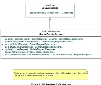
Figure 1 is a simple UML diagram summarizing the SPS interface. This class diagram shows that the SPS interface class inherits the getCapabilities operation from the OGCWebService interface class, and adds the SPS operations. (This capitalization of names uses the OGC/ISO profile of UML.) A more complete UML model of the SPS interface is provided in the following subclauses.
«interface»
OGCWebService
+ getCapabilities(GetCapabilities) : Capabilities
«OGCWebService» SensorPlanningService
+ describeTasking(DescribeTaskingRequest) : DescribeTaskingRequestResponse + getFeasibility(GetFeasibilityRequest) : GetFeasibilityRequestResponse
+ submit(SubmitRequest) : SubmitRequestResponse + getStatus(GetStatusRequest) : GetStatusRequestResponse + update(UpdateRequest) : UpdateRequestResponse + cancel(CancelRequest) : CancelRequestResponse
+ describeResultAccess(DescribeResultAccess) : DescribeResultAccessRequestResponse
Each server instance instantiates only one object of this class, and this object always exists while the server is available.
Figure 6: SPS interface UML diagram
NOTE In this UML diagram, the request and response for each operation is shown as a single parameter that is a data structure containing multiple lower-level parameters, which are discussed in subsequent clauses. The UML classes modelling these data structures are included in the complete UML model in Annex C.
10.2 SPS Operations Usage
Each of the eight SPS operations is described in more detail in subsequent clauses. To simplify the understanding of the information model behind the different operations, some annotated sequence diagrams in UML notation will follow.
The first diagram illustrates the first steps that usually occur during a SPS interaction. An actor (which might be a user with a client GUI or another service) first requests an
overview of the capabilities of the SPS. It provides information about the phenomenons and sensors that can be tasked using this SPS. If the user wants further information upon access of the data that is produced by the façaded sensors, a DescribeResultAccess operation would be used. In this example, we presume that the user received sufficient information as part of the Capabilities document at this stage. Therefore, the next step is to find out which parameters have to be provided to task an asset. This is done using the DescribeTasking operation. The response provided by the SPS defines the parameters that have to be set for each sensor.
Next might be a GetFeasibility request to obtain information if a specific task is feasible. This operation is primarily used to find out if a specific task is likely to be executed under the current conditions. Imagine a UAV that shall make some pictures of a specific area. It has to be checked if the requestor is allowed to operate the UAV, if the requested area fits into the UAV flight plan or if it could be adapted to fit etc. If the
GetFeasibilityRequestResponse indicates that the request is likely to be executed (there might be always some late change in the conditions that enforce a previously feasible task not to be feasible anymore; e.g. if another requestor with a higher priority wants to fly the UAV into the opposite direction), the actor will send the Submit request. The Submit request may contain the feasibilityID or data for all parameters.
Copyright © 2007 Open Geospatial Consortium, Inc. All Rights Reserved. 37 Actor
1) First find out what asset system the SPS facades.
2) Find out which parameters have to be provided to run a task for a specific AMS.
4) Submit transfers the tasking request to the A SPS beforehand or defines new parameters f authorization etc.) the SPS will send status inf taskID provided. In case that the required oper description of an alternative.
getCapabilities
.(capabilities)
describeTasking
.(DescribeTaskingRequestResponse)
getFeasibility
getFeasibility(AMS_specific_payload)
.(GetFeasibilityRequestResponse)
.(GetFeasibilityRequestResponse)
Submit
submit(AMS_specific_payload)
.(Status_Information) .(SubmitRequestResponse)
Asset Management
System
3) The feasibility analysis is an optional step. It is only used in case that the actor wants to find out if a specific task is feasible before submitting it. This request will be forwarded to the asset using asset specific protocols and encodings. It might even be possible that a human will answer the request.
Asset
task(asset_specific)
MS. The client may use a feasibilityID that was provided by the or this task. Depending on different variables (asset availability, ormation back to the actor. Ideally the task is confirmed and a
Figure 7: Annotated sequence of the usual steps occurring to submit a task (UML notation)
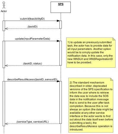
The next diagram shows how to interact with a SPS after a task was submitted successfully. We see the update and the describeResultAccess operation that was introduced with this version of the SPS specification.
Actor
SPS
1) to update an previously submitted task, the actor has to provide data for all input parameters. Another option would be to simply update the notification data. In this case, only the new WNSUrl and WNSRegsitrationID have to be provided.
2) The standard mechanism described in older, deprecated versions of the SPS specification to inform the user where to retrieve the data was to include the SOS data in the notification message that is send to the user after task completion. Because this is not always an option (the data might be available at any other service interface or the actor wants to find out about the data itself even before submitting a task), the
describeResultAccess operation is introduced.
submit(feasibilityID)
.(taskID)
update(inputParameterData)
.(taskID, status)
describeResultAccess(taskID, sensorID)
.(serviceType, serviceURL)
Figure 8: Annotated sequence showing the update and describeResultAccess operations in UML notation