Chapter 2
Contact of rough surface: a literature survey
2.1.Basics of Contact Mechanics
2.1.1 Introduction
Contact phenomena are abundant in everyday life and play a very important role in engineering structures and systems. They include friction, wear, adhesion and lubrication, among other things; are inherently complex and time dependent; take place on the outer surfaces of parts and components, and involve thermal, physical and chemical processes. Contact Mechanics is the study of relative motion, interactive forces and tribological behavior of two rigid or deformable solid bodies which touch or rub on each other over parts of their boundaries during lapses of time. However, the contact between deformable bodies is very complicated and it is not yet well understood.
adhesive elastic contact. This rejection proved to be instrumental in the development of the Tabor [4] and later Maugis [5] parameters that quantify which contact model (of the JKR and DMT models) represent adhesive contact better for specific materials.
Further advancement in the field of contact mechanics in the mid-twentieth century may be attributed to names such as Bowden and Tabor [58]. They were the first to emphasize the importance of surface roughness for bodies in contact. Through investigation of the surface roughness, the true contact area between friction partners is found to be less than the apparent contact area. Such understanding also drastically changed the direction of undertakings in tribology. The works of Bowden and Tabor yielded several theories in contact mechanics of rough surfaces.
The contributions of Archard [6] must also be mentioned in discussion of pioneering works in this field. Archard concluded that, even for rough elastic surfaces, the contact area is approximately proportional to the normal force. Further important insights along these lines were provided by Greenwood and Williamson [7], Bush [8], and Persson [9]. The main findings of these works were that the true contact surface in rough materials is generally proportional to the normal force, while the parameters of individual micro-contacts (i.e. pressure, size of the micro-contact) are only weakly dependent upon the load.
2.1.2 Elastic Contact
In the elastic contact surface areaAe, contact forcePe, maximum contact pressurepm, and average contact pressure pcan be expressed in function of interference . Derived from Hertz’s theory [1] equation contact surface area for elastic contact is given by Ae for elastic contact:
R
Ae ... (2.1)
Contact force Pe derived from equation E apm 2
3
Maximum contact pressure pm obtained from equation E
Average pressure contact elastic, pis given by:
2
In 1951 Tabor [13] stated that the maximum Hertz contact pressure reaches
H
kH
p ... (2.5)
Relationship between maximum contact pressures with hardness at the time of the initial yield point is given by Chang, Etsion and Bogy. It expressed by the equation:
kH
pm ... (2.6)
By subtituting Equation (2.6) into Equation (2.3), critical interference 1CEB is given by:
Kogut dan Etsion (KE model) [12] use value k from [10], so critical interference 1KE at the begining of yield:
2.1.3 Fully Plastic Contact
Fully plastic contact occurs when interference increased to reach 2 with average contact pressure p reach value H(Fig 2.1). In fully plastic contact, Zhao, Maietta and Chang using contact plastic model [11].
Figure 2.1: Deformation on asperity [8].
During deformation fully plastic
2ZMC
average contact pressure remains constant at a value H or:H
ppZMC ... (2.10)
The contact surface area for the fully plastic contact ZMC model using modeling of plastic contacts [11] is given by:
R
ApZMC 2 ... (2.11)
Contact forces Pp equal with the contact surface area multiplied by the average contact pressure.
H R
PpZMC 2 ... (2.12)
Zhao, Maietta and Chang estimated minimum value 2 based on the results
the fully plastic Pp ( = 2) approximately equal to four hundred times the contact
force at the point of initial yieldPy ( =1) or:
400 y p P
P ... (2.13)
By using equation (2.2) is obtained as follows:
2 3 1 2 1
3
4
R E Py
... (2.14)
and
2 3 2 2 1
3
4
R E Pp
... (2.15)
By dividing Equation (2.15) with Equation (2.14) is obtained:
2 1
32 Pp Py 400 ... (2.16)or
1 2 54
... (2.17)
From the equation above, Zhao, Maietta and Chang (ZMC model) [11] defines the value of interference in the fully plastic 2ZMC limit to the value of critical interference at the yield point 1ZMC by the equation:
ZMC ZMC 1_ 2 54
... (2.18)
KE deformation. Relations between contact surface area and average contact pressure as a function of the interference is a very complex relationship. Zhao, Maietta and Chang (ZMC model) [11] gives the relationship between the average contact pressure and interference in elastic-plastic contact is given by:
Whereas the surface area contact on the elastic-plastic expressed as:
By using equation (3.20) and (3.21) the elastic-plastic contact force is the product between the average contact pressures with the contact surface area which yields:
Kogut and Etsion [12] give the relationship an average contact pressure against interference in elastic-plastic contact with the equation:117
where Y is the yield strength of the material.
While the relationship between surface areas in contact in the interference functions of elastic-plastic contact is given in the equation:
136
2.2 Surface Topography: Surface Texture, Roughness, Waviness
to the surface and the latter in the plane of the surface. The distribution of height is measured from a reference plane (say, mean plane).
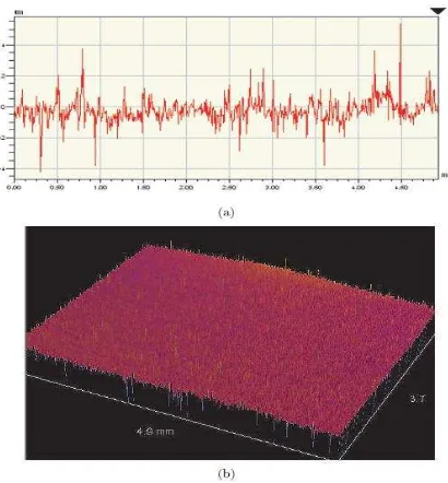
The characterization of a surface may be one dimensional (1-D) or two dimensional (2-D) depending upon the machining and finishing process. For 1-D case, height (z) varies with one of the coordinates, whereas in other coordinate there exists a lay where variation of z is comparatively small. But for surfaces made by conventional manufacturing processes, when 1-D characterization is not proper, 2-D surface roughnesses description is required. Atomic Force Microscope (AFM) and 3D surface profilometer are used to improve the resolution and accuracy of the roughness measurement. Typical 1-D and 2-D representation of nominally flat surfaces (polished) are shown in Figure 2.2. (a) and 2.2. (b). Scale used for the height is much larger than that for the wavelength because the height of the asperities from the mean plane is very less compared to their wavelengths [16].
Figure 2.2: Typical representation of a surface: (a) one-dimensional (b) two-dimensional [16].
2.3 Contact Problem of Smooth Surfaces
their nominal geometry, the second admits that all surfaces are comprised of multitude of peaks and valleys which have multiple asperities which is regarded as a rough surface. Hertz [1] was first to analyze the elastic contact between two non-conforming spheres. He gave the analytical solution for the normal contact between two curved bodies for contact pressure and subsurface stress field.
In Hertz analysis, following assumptions were made.
a) Radii of curvature of the contacting bodies are large compared with radius of circle of contact.
b) Contact is frictionless.
c) Surfaces are continuous and non-conforming. d) Strain is small.
e) Each solid can be considered as half space.
Based on these assumptions, the stress fields generated by an indenter contacting an elastic solid can be analyzed [17]. For the case of elastic contact with a spherical indenter of radius R, the radius of the circle of contact a between the indenter and the specimen surface increases with the load. The contact pressure distribution p proposed by Hertz is given by
⁄
The total contact load P can be obtained from the above pressure distribution as,
∫
Where maximum pressure = 3/2 , with denoting the mean pressure. The contact circle radius a is given by,
is the effective modulus of elasticity and is the effective radius of curvature defined as,
, , are the Young’s modulus, Poisson’s ratio and radius of curvature of the indenter material and , , are the corresponding parameters of the specimen. The depth of indentation h is related to indenter radius by,
2.4 Contact Problem of Rough Surface
Traditionally, surfaces were modeled analytically using assumption and simplifications. Surface produced by any conventional machining/manufacturing processes are never smooth. The surface irregularities are termed as asperities. Asperities were modeled as a variety of geometric shapes. In the past, a number of authors study rough surface contact problem using analytical method (Whitehouse & Archad [19]; Onions & Archad [20]; Bush, Gibson, et al, [8]; Hisokado [23]). Their result was very useful but their application is limited to a relatively small range of loads.
Surface asperity height and contact pattern were treated as probability distributions. Behavior of a single pair of interacting asperities was often extrapolated to describe the behavior of a pair of interacting surfaces covered in asperities [25]. Investigation of the contact itself classically follows two types of approach, either stochastically or deterministically. One of the first models has been proposed by Greenwood and Williamson [7], who assumed that the asperity summits are spherical with a constant radius, the asperities deform elastically and their height follows a Gaussian distribution. Statistical models have had a considerable impact on contact analysis and have been considered by many authors [28-31]. Nevertheless, these models do not take into account the real geometry of the surface and the interactions between the asperities. Deterministic approaches were then developed to introduce a more precise geometric description [41].
Surface roughness can affect the performance of components and system in a wide variety of fields including tribology, fluid sealing, heat transfer, electronic packaging, dentistry, and medicine. Although it is possible to measure the topography of a real surface and incorporate that data into a finite element model [32-34], this practice is still relatively uncommon [35].
been used to solve the contact problem for artificial fractal surfaces [46]. Starting from roughness measurements, synthesized fractal surfaces were also used in the studies of Vallet et al. [44-45] where they used a numerical procedure to solve the contact problem.
2.5 Modeling Rough Surface
The classical analysis of rough surface contact problems were based upon statistical models. Their asperities were assumed to have a certain shape and their physical dimensions such as the widths and the heights were assumed to have a certain statistical distribution. The rough surface is represented by a collection of asperities of prescribed shape scattered over a reference plane. The height of the summits has a statistical distribution and is assumed that the contacting asperities deform elastically according to Hertz theory.
Many models describing rough surface have followed the pioneering work of Abbot & Firestone [43]. They attempt to characterize roughness by a series of indicators, such as the arithmetic average of vertical deviation Ra and the mean line m,
the root mean squared Rs or the standard deviation σ. However, the surface can’t be
fully described using only a surface profile in the vertical direction. These were done in order to simplify the problem. With the rapid advances of faster computers within the last decade, the development of more realistic models for contact simulation becomes more feasible.
spots, and asperity contact along with their distribution for different surface roughness and effect of σ (height distribution/surface roughness) and β* (spatial structure of a
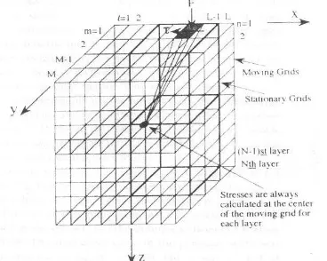
surface). The result is compared with Bush’s model [8] using stochastic approach. Lee and Cheng [52] also using a computer simulation to made a model for the contact between longitudinally oriented rough surface for simulating contact between purely longitudinal surface. During that time, simulating a model in computer was really taking a lot of time. Several methods were investigated to increase time efficiency and reduce the requirement of the computer memory size. Lee & Ren [53] developed simulating dry contact of three-dimensional rough surface based upon Moving Grid Method (MGM). Its method was able to reduce required RAM (320 Kb from previous 12.8 GB). It method reduce required storage space for deformation matrix to the order of N (Fig 2.3). The computing time to construct the matrix is also proportional to N.
Figure 2.3: A schematic of representation of the three dimensional moving grid method [52].
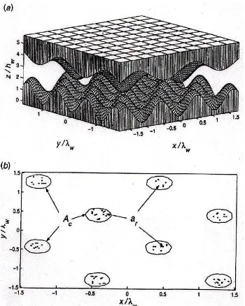
which the nominal contact area may be arbitrarily large that both wavy and rough (Fig 2.4).
Figure 2.4: A schematic three dimensional model of Karpenko [54].
Another method to generate rough surface such as successive random midpoint algorithm is used by Pei, et al. [55] when they presented a finite element calculation of frictionless, non-adhesive, contact between a rigid plane and an elasto-plastic solid with a self-affine fractal surface (Fig. 2.5.). All of the rough surface research mentioned above are generated by digitized measured profile of contacting surface and used them for computer simulation.
Bryan et,al. [47] lately analyze elastic-plastic finite element of line contact between cylinder and rigid plane using ABAQUS. However, they still generated rough surface from measured real surface which imported to ABAQUS using a Phyton script (Fig 2.6). Another finite element research lately from Yastrebov & Durand [48] presented normal frictionless mechanical contact between an elastoplastic material and rigid plane using finite element analysis (FEA) and representative surface element (RSE) approach. Their research also introduced a new reduced model for the analysis of rough surface. Their new model can solve problem in a few second instead of FEA that need a few days. The new model is a series of basic curves obtained by means of elementary finite element computation on a single asperities and phenomenological relations to take into account the interaction between neighboring asperities of the rough surface.
Figure 2.6: Measured rough surface model by Bryant & Evans [46].
2.6 Three Dimensional Model of Rough Surface in Finite Element
Commercial Software
Traditionally, surfaces were modeled analytically using assumptions and simplifications. Asperities were modeled as a variety of geometric shapes. Surface asperities height and contact pattern were treated as probability distributions. The behavior of single pair of interaction asperities was often extrapolated to describe the behavior of a pair of interacting surfaces covered in asperities. These assumptions were not made because they were shown to accurately represent the system of interest, but because they made modeling possible. Therefore, people studied rough surface by mean analyze one single asperity which assumed represent the others asperities of the surface. The topography of surface was taken from measured real surface using optical micro and macro scale surface features and record data digitally.
Schwarzer [56] geometrically construct all sort of rough surfaces by applying mathematical functions. Figure 2.7 shown an example of two surface of equal roughness in a mere mathematical contact situation, yet this model cannot represent the real surface due to the asperities which are homogeny.
Figure 2.7: Model of rough surface from Schwarzer [56].
is studied through experiments and finite element simulation. The well defined roughness profile is made up of a regular array of pyramidal asperities.
Figure 2.8: Rough surface modeled by Bhowmik [16].
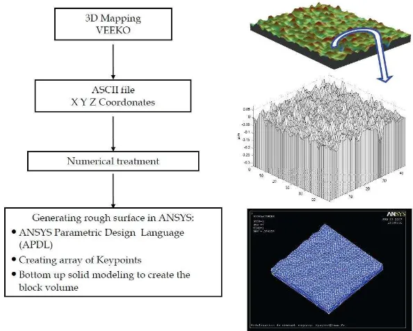
David et, al.[49] demonstrated RF MEMS simulation. They used either an optical profilometer (VEECO) or an Atomic Force Microscope (AFM) to capture three dimensional data points of contact surfaces. Then, using Matlab functions they convert the closed surface from a stereo-lithographic format to an ASCII file compatible with ANSYS Parametric Design Language (APDL). In the final step, the rough surface was obtained by creating key points from the imported file. Since the key points are not co-planar, ANSYS uses Coons patches to generate the surface, and then we used a bottom up solid modeling to create the block volume with the rough surface on the top. Figure 2.9 describes the full method developed on ANSYS platform. Meanwhile Figure 2.10. shows rough surface interface in ANSYS.
Figure 2.10: Methodology for generating rough surface from David et,al [48].
M Kathrine Thompson [26] from mechanical department MIT, presents methods for generating, using, and operating on nonuniform variates for the incorporation of probabilistic rough surfaces in ANSYS (Fig. 2.11). Her work discusses how to decouple the surface from the finite element model by transferring the surface information from arrays to tables.
The methods are presented for creating solid model geometry from the metrology data. Three example surfaces are imported and used in a contact analysis. For this work, surface metrology data is imported into the finite element program as a two dimensional array. These techniques, combined with the ability to model real surfaces in ANSYS, can be used to help researchers in material science, mechanical and electrical engineering, and beyond to better understand micro scale surface phenomena. However,
Thompson’s model shows asperities with sharp peak instead of smooth. Meanwhile, in the real rough surface, the geometry of the asperities is considered as either hemisphere or ellipsoid as have been proved by previous works on modeling asperities from
measured real surface. Moreover, Thompson’s model is difficult to be meshed because
of its manipulated geometry. This paper will discuss a new way to generate surface in ABAQUS with surface treatment in SolidWorks. Rough surface with smooth asperities is expected as the result of this work. The model behavior from this method will be compared with surface that created normally from ABAQUS.
References
1. Hertz, H., 1882, Uber die beruhrung fester elastische korper and uber die harte, Verhandlungen des Vereins zur Beforderung des Gewerbefleisses, Leipzig. 2. Johnson, K.L., Kendall K., and Roberts, A.D., 1971, Surface energy and the
contact of elastic solids, Proceedings of the Royal Society of London. Series A, pp. 324 301-313.
3. Derjaguin, B.V., Muller, V.M., and Toporov Y.P., 1975, Effect of contact deformations on the adhesion of particles, Journal Colloid Interface Science, pp. 53 314—325.
4. Tabor, T., 1977, The hardness of solids, Journal Colloid Interface Science 58, pp. 145-179
6. Archard, J.F, 1957, Elastic deformation and the laws of friction, Proceedings of the Royal Society of London. Series A, Mathematical and Physical Sciences, 243(1233), pp.190-205.
7. Greenwood, J.A., and Williamson, J.B.P., 1966, Contact of nominally flat surfaces, Proceedings of the Royal Society of London. Series A, Mathematical and Physical Sciences, pp. 300-319.
8. Bush, AW., Gibson, R.D., and Thomas, T.R., 1975, The elastic contact of a rough surface, Wear, 35(1), pp. 87-111.
9. Persson, B.N.J., Bucher, F., and Chiaia, B., 2002, Elastic contact between randomly rough surfaces: Comparison of theory with numerical results, Physical Review B, 65(18), pp. 184-196.
10.Chang, W.R., Etsion, I., and Boggy, D.B., 1987, An elastic-plastic model for the contact of rough surfaces, ASME Journal of Tribology, Vol. 109, pp.257-263. 11.Zhao, Y., Maietta, D. M., and Chang, L., 2000, An asperity microcontact model
incorporating the transition from elastic deformation to fully plastic flow, ASME Journal of Tribology, Vol. 69, pp.657-662.
12.Kogut, L., and Etsion, I., 2002, Elastic-plastic contact analysis of a sphere and a rigid flat, ASME Journal Appl. Mech, Vol. 69, pp. 657-662.
13.Tabor, D., 1951, The hardness of metals, Oxford University Press, Oxford, UK. 14.Johnson, K. L., 1985, Contact Mechanics, Cambridge University Press,
Cambridge, UK.
15.Song J.F., Vorburger T.V., 1992, Surface Texture ASM Handbook, ASM, New York.
16.Bhowmik, K., 2007, Exsperimental and Finite Element Study of Elastic-plastic Indentation of Rough Surface, Master thesis, Departement of Mechanical Enginering, Indian Institute of Science.
17.Fischer-Cripps A.C., 2000, Introduction to Contact Mechanics, Springer-Verlag, New York.
19.Whitehouse D.J. and Archard J.F., 1970, The properties of random surfaces of significance in their contact, Proc. Royal Soc. Lond. 316A, pp 97-121.
20.Onions R.A., Archard J.F., 1973, The contact of surface having a random structure, Journal Physics. D: App. Physics. 6, pp. 289-304.
21.Nayak P.R., 1971, Random process model of rough surfaces, Journal Lubrication Technology. 93,pp. 398-407.
22.Bush A.W., Gibson R.D., and Thomas T.R., 1975, The elastic contact of a rough surface, Wear 35, pp. 87-111.
23.Hisakado T., 1974, Effect of surface roughness on contact between solid surfaces, Wear 28, pp. 217-234.
24.Francis H.A., 1977, Application of spherical indentation mechanics to reversible and irreversible contact between rough surfaces, Wear 45, pp. 221-269.
25.McCool J.I., 1986, Comparison of models for the contact of rough surfaces,Wear 107, pp. 37-60.
26.Thompson, M. K., 2007, A Multi-scale Iterative Approach for Finite Element Modeling of Thermal Contact Resistance. Ph.D. Thesis, Massachusetts Institute of Technology, Departement of Mechanical Engineering.
27.Whitehouse, D,J., Archard, J.F., 1970, The properties of random surface of significance in their contact, Proceedings of the Royal Society of London Series A 316, pp. 97–121.
28.Bush A.W., Gibson R.D., Thomas, T.R., 1992, The elastic contact of a rough surface, Wear 153, pp. 53–64.
29.Bush, A.W., Gibson, R.D., Keogh, G.P., 1979, Strongly anisotropic rough surfaces, Journal of Lubrification Technology 101 pp. 15–20.
30.Bush, A.W., Gibson, R.D., 1987, The elastic contact of a rough surface, Wear 35, pp. 87–111.
31.Bucher F., Knothe K., Theiler A., 2002, Normal and tangential contact problem of surfaces with measured roughness. Wear 253(1-2), pp. 204-218.
33.Walter, C., Antretter, T., 2009, 3D versus 2D finite element simulation of the effect of surface roughness on nanoindentation of hard coatings. Surf Coatings Technol 203, pp. 3286–3290.
34.Walter, C., Antretter, T., Daniel, R., Mitterer, C., 2007, Finite element simulation of the effect of surface roughness on nanoindentation of thin films with spherical indenters. Surf Coating Technol 202, pp. 1103–1107.
35.Thompson, M. K. and Thompson, J. M., 2010, Considerations for the incorporation of measured surfaces in finite element models. Scanning Vol. 31, pp. 1-16.
36.Chilamakuri, S. K., and Bhushan, B., 1998, Contact analysis of non-Gaussian random surfaces. Proceeding Institution Mechanical Engineers. Vol. 212, Part J. 37.Peng, W. and Bhushan, B., 2001, A numerical three-dimensional model for the
contact of layered elastic/plastic solids with rough surfaces by variational principle. Trans. ASME, Joornal Tribology, 123, pp. 330-342.
38.Zhang, X., Cong, P., Fujiwara, S., Fuji, M., 2004, A new method for numerical simulation of thermal contact resistance in cylindrical coordinates. International Journal Heat and Mass Trans., 47, pp. 1091-1098.
39.Kim, T.W., Bhushan, B., 2006, Generation of composite surfaces with bimodal distribution and contact analysis for optimum tribological performance. Journal Tribology, 128, pp. 851-863.
40.Tang, J., Tieu, A. K., and Jiang, Z. Y., 2006, Modelling of oxide scale surface roughness in hot metal forming. Journal of Materials Processing Technology, 177, pp. 126-129.
41.Jamari, J., and Schipper, D.J., 2007, Deterministic repeated contact of rough surfaces. Wear 264, pp. 349-358.
42.Jamari, J., and Schipper, D.J., 2006, Experimental investigation of fully plastic contact of a sphere against a hard plat. Trans. ASME, Journal Tribology, 128, pp. 230-235.
44.Vallet, C., 2008, Fuite liquide au travers d’un contact rugueux : application
l’étanchéité interne d’appareils de robinetterie. PhD thesis, Ecole Nationale
Supérieure d’Arts et Métiers.
45.Vallet, C., Lasseux, D., Zahouani, H., Sainsot, P., 2009, Sampling effect on contact and transport properties between fractal surfaces, Tribology International 42, pp. 1132–1145.
46.Sainsot, P., Jacq, N., Nelias, D., 2002, A numerical model for elastoplastic rough contact, CMES 3 (4), pp. 497–506.
47.Bryant, M.J., Evans, H.P., Snidel, R.W., 2011, Plastic deformation in rough surface line contacts-a finite element study. Journal of Tribology International, in press.
48.Yastrebov, V.A., Durand, J., Proudhon, H., Cailletaud, G., 2011, Rough surface contact analysis by mean of the finite element method and a new reduced model, Comptes Rendus Mecanique 339, pp. 473-490.
49.David, P., et al., 2008. A new methodology for RF MEMS simulation. In Tech, ISBN 978-3-902613-25-7. pp. 433-452.
50.Webster, M,N., Sayles R.S., 1986, A numerical model for the elastic frictionless contact of real rough surfaces, ASME, Journal Tribology, 108, Issue 3, pp. 314 – 320.
51.Poon, C.Y., Sayles, R.S., 1994, Numerical contact model of a smooth ball on anisotropic rough surface, ASME, Journal Tribology, 116, Issue 3, pp. 194 – 202.
52.Lee, S.C., Cheng, H.S., 1992, On the relation of load to average gap in the contact between surfaces with longitudinal roughness, Tribology Transaction, Vol 5, Issues 3, pp. 523-529.
53.Ren, N., Lee, S,C., 1993, Contact simulation of three-dimensional rough surfaces using moving grid method, ASME, Journal Tribology, 115, Issue 4, pp. 597 – 602.
55.Pei, L., Hyun, S., Molinari, J,F., Robbins, M,O., 2005, Finite element modeling of elasto-plastic contact between rough surfaces. Journal of the Mechanics and Physics of Solids, 53, pp. 2385-2409.
56.Schwarzer, N., 2007. Modelling of contact problems of rough surfaces, publication of the Saxonian Institute of Surface Mechanics,
www.siomec.de/doc/2007/007.
57.Chang, L., Gao, Y., 1999, A simple numerical method for contact analysis of rough surfaces, ASME Journal Tribology, 121, pp. 425–432.
![Figure 2.1: Deformation on asperity [8].](https://thumb-ap.123doks.com/thumbv2/123dok/2244556.1231909/5.595.144.490.225.355/figure-deformation-on-asperity.webp)
![Figure 2.6: Measured rough surface model by Bryant & Evans [46].](https://thumb-ap.123doks.com/thumbv2/123dok/2244556.1231909/16.595.174.512.381.543/figure-measured-rough-surface-model-bryant-evans.webp)
![Figure 2.7: Model of rough surface from Schwarzer [56].](https://thumb-ap.123doks.com/thumbv2/123dok/2244556.1231909/17.595.170.484.475.592/figure-model-rough-surface-schwarzer.webp)
![Figure 2.9: Interface of rough surface on ANSYS [48].](https://thumb-ap.123doks.com/thumbv2/123dok/2244556.1231909/18.595.253.398.189.326/figure-interface-rough-surface-ansys.webp)