Contact Width Analysis of Corrugated Metal Gasket Based on Surface
Roughness
Shigeyuki Haruyama
1,a, Didik Nurhadiyanto
2,b, Ken Kaminishi
3,c1
Management of Technology, Yamaguchi University, 2-16-1 Tokiwadai, Ube-shi, Yamaguchi, Japan
2
Doctoral student at Department of Mechanical Engineering, Yamaguchi University, Japan
Lecturer at Mechanical Education Engineering Department, Yogyakarta State University, Indonesia
3
Management of Technology, Yamaguchi University, 2-16-1 Tokiwadai, Ube-shi, Yamaguchi, Japan
a
[email protected], [email protected], [email protected]
Keywords: Surface roughness, contact width, microscope, gasket, groove.
Abstract. Contact width is important design parameter for optimizing design of new metal gasket. The contact width was found have relationship with helium leak quantity. Increasing axial force, the contact width will increase and helium leakage will decrease. This study we conducted the surface roughness evaluation of 25A-size metal gasket before and after use. The results denote the real contact width after contact with flange having different surface roughness. The real contact width for the flange having smoother surface roughness is wider than the rougher one.
Introduction
As a replacement for gaskets containing asbestos material, many researchers have studied the use of metal gasket materials. Saeed et al. studied a new 25A-size corrugated metal gasket that was developed as an asbestos gasket substitute. The gasket had a metal spring effect and produced high local contact stress to create a sealing line with a flange. The results showed that the contact stress and contact width were important design parameters for optimizing the gasket performance [1]. Haruyama et al. [2] continued this research. The size limit of the contact width as a gasket design parameter was investigated. Comparing the results of FEM analysis of the relationship between the clamping load of the flange and the contact width with experimental results for the clamping load and leakage clarified the contact width with no leak for the new 25A-size metal gasket. Based on this result, the contact width can be used as a main parameter to optimize the gasket design. The leakage can be reduced by increasing the contact width. Nurhadiyanto et al. [3] used FEM to study the optimization of gasket design based on an elastic and plastic contact stress analysis by considering the forming effect. A helium leakage test showed that a gasket based on a plastic contact stress design was better than a gasket based on an elastic stress design.
The characteristic becoming important in next development target of new metal gasket is a function to prevent a leak depending on use a surface roughness standard. Leakage is a function of surface roughness [4]. If surface roughness increase, leakage also increases. Haruyama et al. [5] studied a contact width, contact stress, and force per unit length for gasket in contact with a flange having different surface roughness levels using FEM. A smoother of surface roughness has higher slope for force per unit length. The higher slope suggests that the gasket and flange are pressed together strongly. Based from the reason, the aim of this study is determine the surface roughness of a flange contact with metal gasket. It realized by experimental analysis to check the contact width after tightening process according to surface roughness of flange. After the axial force applied, the grooves will be formed in the gasket adjusted the shape of the flange roughness. Focus of this study is investigated the total number of grooves width formed in a gasket. The total number of grooves width is the real contact width during the tightening.
Material and Method
The gasket used in this research is circumference beads gasket. The shape of gasket is produced by mold press. When a gasket is tightened to the flange, each bead of both surfaces created elastic effect and produce high local contact stress to prevent leakage. The dimension of gasket used is standard dimension based on JISB2404 [6] with 1.45 mm of gasket thickness. The gasket material was SUS304 due to its effectiveness in high-temperature and high-pressure environment. In order to ensure the properties of the material, SUS304 was initially validated using tensile test carried out based on JISZ2241 [7]. From the tensile test result, the nominal stress of SUS304 was 398.83 MPa, the tangent modulus was 1900.53 MPa and the modulus of the elasticity (E) was 210 GPa.
The general-purposed flange based on JISB2220 [8] with 10 K pressure and 25A diameter used in this test. The lower flange and the joint were welded carefully to avoid a distortion, the information of this gasket completely in [4]. Types of flange based on the average surface roughness, are 1.5μm, 2.5μm, and 3.5μm. The new 25A-size metal gasket with corrugated shape was used in this test. In this research, two types of gasket and three levels of flange surface roughness were investigated. Types of gasket, based on elastic and plastic design, are 0-MPa and 400-MPa mode, the information of this gasket completely in [4].
The previous study confirmed that if surface roughness is increased the leakage will decreased. The simulation in the previous study proved that smoother of surface roughness will increase the contact width [5]. The points of measurement are performed at two point of contact width, which are convex number 2 and 3. Because this part is effective for avoiding leak is taken as evaluation part as explained in [5]. The digital microscope VH-Z250 series with 500x magnification was used to measure the contact width parameter of the proposed the 25-A size metal gasket. Using the microscope we can measure the width of grooves which is the real contact width between the flange and the gasket.
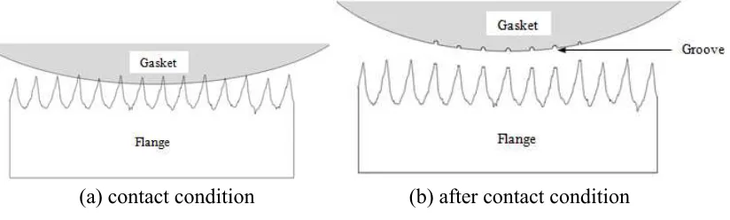
(a) contact condition (b) after contact condition
Fig. 1 Gasket and flange in contact and after contact condition
There are grooves in the gasket after contact with flange, see Fig.1. The tightening process is carried out based on the axial force. Tightening the flange using bolts can cause to high local contact stress on the convex section of the gasket. Groove will be formed in the gasket as an illustration of pressure distribution profile that occurred between the two surfaces. Focus of current study was to observe the width of the groove formed in the gasket. The total number of grooves width is a real contact width between gasket and flange, see equation (1).
Results and Discussion
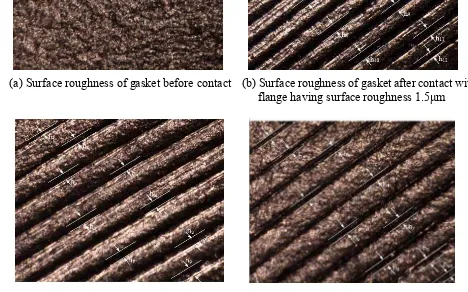
(a) Surface roughness of gasket before contact (b) Surface roughness of gasket after contact with flange having surface roughness 1.5μm
(c) Surface roughness of gasket after contact with (d) Surface roughness of gasket after contact with flange having surface roughness 2.5μm flange having surface roughness 3.5μm
Fig. 2 Grooves formed conditions for gasket 400-MPa mode
Fig. 2 shows the surface roughness condition of gasket 400-MPa mode before and after contact with flange. The surface roughness of gasket before contact with flange is shown in Fig. 2(a). There were no grooves in the gasket surface. The surface roughness of gasket after contact with flange having surface roughness 1.5μm, 2.5μm, and 3.5μm, respectively, are shown in Fig. 2(b), (c), and (d). There were grooves in the gasket surface. The grooves formed because of the tightening process between upper and lower rough flange. Based from the figures, we got the real contact width between gasket and flange. The real contact width is the total number of grooves width as described in equation (1). More detail for the real contact width for gasket 400-MPa mode contact with flange shown in Table 1.
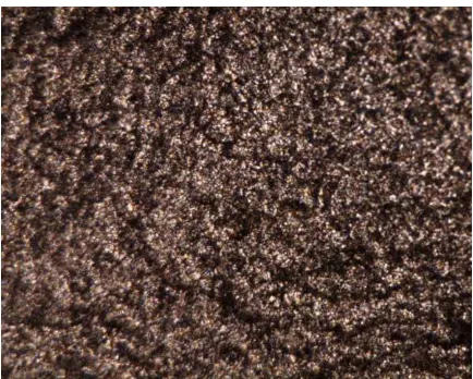
(a) Surface roughness of gasket before contact (b) surface roughness of gasket after contact with flange having surface roughness 1.5μm
(c) surface roughness of gasket after contact with (d) surface roughness of gasket after contact with flange having surface roughness 2.5μm flange having surface roughness 3.5μm
Fig. 3 Grooves formed conditions for gasket 0-MPa mode
Table 1. Contact width result for 400-MPa gasket mode
Ra 1.5 μm Ra 2.5 μm Ra 3.5 μm
Convex 2 Convex 3 Convex 2 Convex 3 Convex 2 Convex 3
17.49 19.67 24.04 13.11 8.74 21.86
25.14 26.23 26.23 14.21 17.49 20.77
21.86 32.79 30.6 18.58 19.67 19.67
26.23 20.77 28.42 32.79 20.77 19.67
21.86 27.32 26.23 30.27 21.86 18.58
24.04 26.23 31.69 28.85 19.67 18.58
27.32 28.42 29.18 22.13 21.86 20.77
29.51 26.23 25.9 28.85 21.86 20.77
25.14 27.32 22.62 20.27 18.58 19.67
29.51 28.42 30.6 15.3 15.3
25.14 32.79 17.49 12.79
273.24 308.98 244.91 239.66 185.8 195.64
Average: 291.11 Average: 242.285 Average: 190.72
Table 1 shows the real contact width results for the gasket 400-MPa mode after contact with flange
having surface roughness 1.5μm, 2.5μm, and 3.5μm, respectively, for all levels surface roughness.
The gasket contact with flange having surface roughness 1.5μm shows the widest real contact width
The gasket contact with flange having surface roughness 3.5μm shows the shortest real contact width
both for convex number 2 and 3. The average contact width for convex number 2 and 3 is 190.72μm. This result is in line with the simulation result in [5]. Correspond the statement above and based on the real contact width measurement flange having surface roughness 1.5μm is the best flange for
decrease leakage and flange having surface roughness 3.5μm is worst for decrease leakage. It means
that the smoother surface roughness will decrease the leakage for the gasket 400-MPa mode.
Table 2 shows the real contact width results for the gasket 0-MPa mode for all levels surface
roughness. The gasket contact with flange having surface roughness 1.5μm shows the widest real
contact width both for convex number 2 and 3. The average contact width for convex number 2 and 3
is 235.71μm. Thegasket contact with flange having surface roughness 3.5μm shows the shortest real
contact width both for convex number 2 and 3. The average contact width for convex number 2 and 3
is 155.2μm. This result is in line with the simulation result in [5]. Correspond the statement above and based on the real contact width measurement, flange having surface roughness 1.5μm is the best
flange for decrease leakage and flange having surface roughness 3.5μm is worst for decrease leakage.
It means that the smoother surface roughness will decrease the leakage for the gasket 0-MPa mode.
Table 2. Contact width result for 0-MPa gasket mode
Ra 1.5 μm Ra 2.5 μm Ra 3.5 μm
Average: 235.71 Average: 175.51 Average: 155.2
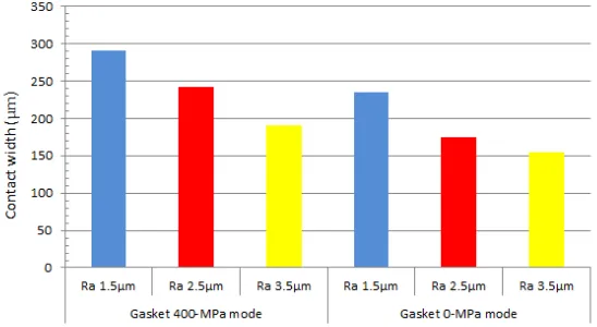
Using Table 1 and 2, we compared the leakage performance of the gasket 400-MPa mode and the gasket 0-MPa mode based on the real contact width. The real contact width for the gasket 400-MPa mode is wider than the gasket 0-MPa mode for each gasket contact with flange having surface roughness 1.5μm, 2.5μm, and 3.5μm, respectively. It means that the leakage performance for the gasket 400-MPa mode is better than the gasket 0-MPa mode.
Fig. 4 shows the contact width between gasket and flange for all levels surface roughness. It is very clear that the real contact width between flange and gasket 400-MPa mode is wider than gasket 0-MPa mode. As explanation above, for the same gasket, the real contact width between gasket and flange having surface roughness 1.5μm is widest than the others. The real contact width between gasket and flange having surface roughness 3.5μm is shortest than others.
Conclusions
This study has given a clear view on the real contact width between the gasket and the flange, which have an important influence on the leakage performance. In addition, comparison made with the surface roughness, serves as visible proof that the proposed surface roughness brought several improvements.
From the experiments conducted, the following conclusions can be drawn:
(1) The real contact width for the gasket 0-MPa mode contact with flange was lower than the gasket 400-MPa mode contact with flange.
(2) The gasket contact with flange having surface roughness 1.5μm shows the widest real contact width both for the gasket 400-MPa mode and the gasket 0-MPa mode. The gasket contact with
flange having surface roughness 3.5μm shows the shortest real contact width both for the gasket
400-MPa mode and the gasket 0-MPa mode.
Acknowledgements
This project was supported by the Strength of Material Laboratory, Yamaguchi University, Japan. The second author is grateful for the scholarship support from the Directorate of Higher Education Indonesia in cooperation with Yogyakarta State University.
References
[1] Saeed, H.A, Izumi, S., Sakai, S., Haruyama, S., Nagawa, M., Noda, H., Development of New Metallic Gasket and its Optimum Design for Leakage Performance, Journal of Solid Mechanics and Material Engineering, Vol. 2, No. 1 (2008), 105–114.
[2] Haruyama, S., Choiron, M.A., Kaminishi, K., A Study of Design Standard and Performance Evaluation on New Metallic Gasket, Proceeding of the 2nd International Symposium on Digital Manufacturing, Wuhan China, (2009), 107–113.
[3] Nurhadiyanto, D., Choiron, M.A., Haruyama, S., Kaminishi, K., Optimization of New 25A-size Metal Gasket Design Based on Contact Width Considering Forming and Contact Stress Effect, International Journal of Mechanical and Aerospace Engineering Vol. 6 (2012), 343-347.
[4] Person, B.N.J., Bucher, F., Chiaia, B., Elastic Contact between Randomly Rough Surfaces: Comparison of Theory with Numerical Results, Phys. Rev. Lett. Vol. 65 (2002), 184106.
[5] Haruyama, S., Nurhadiyanto, D., Choiron, M.A., Kaminishi, K., Surface Roughness of flange Contact to the 25A-size Metal Gasket by Using FEM Simulation, International Journal of World Academy of Science, Engineering and Technology, Vol. 74 (2013), 665-669.
[6] JISB2404, Dimensions of gaskets for use with the pipe flanges, Japanese Standards Assosiations, 2006.
[7] JIS Z2241, Metallic materials-Tensile testing-Method of test at room Temperature, Japanese Standards Association, (2011).
Contact Width Analysis of Corrugated Metal Gasket Based on Surface Roughness