A SEMANTIC MODEL TO DEFINE INDOOR SPACE IN CONTEXT OF EMERGENCY
EVACUATION
Nishith Maheshwaria, K. S. Rajanb
Lab for Spatial Informatics, International Institute of Information Technology, Hyderabad, India -a[email protected],b[email protected]
Commission IV, WG IV/7
KEY WORDS:Evacuation, modeling, indoor space, building environment, navigation network
ABSTRACT:
There have been various ways in which the indoor space of a building has been defined. In most of the cases the models have specific purpose on which they focus such as facility management, visualisation or navigation. The focus of our work is to define semantics of a model which can incorporate different aspects of the space within a building without losing any information provided by the data model. In this paper we have suggested a model which defines indoor space in terms of semantic and syntactic features. Each feature belongs to a particular class and based on the class, has a set of properties associated with it. The purpose is to capture properties like geometry, topology and semantic information like name, function and capacity of the space from a real world data model. The features which define the space are determined using the geometric information and the classes are assigned based on the relationships like connectivity, openings and function of the space. The ontology of the classes of the feature set defined will be discussed in the paper.
1. INTRODUCTION
Planning of emergency evacuation is a crucial part of prepared-ness in case of a disaster or a hazard. Current emergency plans for buildings are basically floor-plans indicating the way to near-est exits. While they serve their purpose well, in a scenario where there is a higher density of people in one part of the building the way to nearest exit may not be the fastest way to get out of the building. To find an optimal evacuation route, all the paths inside the building have to be taken into account along with the conges-tion along these different paths.
Currently there is no data format which explicitly defines the paths for evacuation inside the building. Hence researchers have focused on deriving it from the data models which define the ge-ometry of elements of the buildings. Using such an approach leads to a methodology which cannot be extended to other data models. Hence a need to define the indoor space in an effective manner is required. In our work we have tackled this issue by defining a model based on the understanding of the functional characteristics of the indoor space. It is hoped that the feature set of such a model can be directly converted to a network form. This will allow us to define elements for any kind of data model in terms of our definition of space which then can be used to gen-erate a network for proper evacuation planning.
The rest of the paper is organised as follows. In Section 2, data models which are currently used to define indoor data of a build-ing are discussed along with the review of work done to use these data models in the context of indoor navigation and network gen-eration. Section 3 defines the ontology of the indoor space and the description of the classes of the suggested semantic model. In Section 4 we showcase a case study using the floor-plan of one of the classroom buildings of our institute to represent the spaces in terms of the classes defined and the way a network can be gen-erated using such a definition. Finally the paper is concluded in Section 5 with discussion of how a model like this would help in generation of navigational network along with direction for future work.
2. CURRENT MODELS FOR DATA REPRESENTATION
There are two main data models which are widely used to repre-sent indoor data of a building - IFC and CityGML LOD4. In this section we will briefly talk about them.
IFC is an open standard for Building Information Model (BIM) and is developed and supported by BuildingSMART organisation (buildingSMART International Ltd., 2016). It defines a build-ing in terms of storeys and elements such as spaces, walls, slabs, roofs, openings along with detailed information like thickness and material used. Each of these elements are defined as ob-jects and there is a minimal form of hierarchy usually limited to a storey level. The purpose of IFC data model is to provide interop-erability between the Architecture, Engineering and Construction (AEC) industry (OGC, 2016). Being a volumetric model, one of its primary usage is to estimate the amount of material required for construction of buildings.
CityGML is an open data model format for storing virtual 3D city models (Gr¨oger et al., 2012). Its implementation is done as an application schema of Geographic Markup Language (GML), which is an XML based encoding standard for representing geo-graphic data. It is a multi-scale model which represents data in the form of five levels of details (LODs) from LOD0, which de-fines the footprint of the building, to LOD4, which describes in-terior building installations. CityGML has a thematic extension module calledBuildingswhich define objects like walls, doors and windows in a hierarchical manner. Till LOD3 the represen-tation of the building is in the form of boundary surfaces. LOD4 has the facility to describe the details of objects from furniture to room inside the building.
does not store any semantic and topological relationships which have to be derived through other means.
All the above discussed data models differ in terms of their pri-mary purpose or goal, targeted users, methodology of representa-tion as well as focus on specific elements of the building. Now, to create an indoor navigation framework for emergency evacua-tion, separate methodologies for each of them are required. Re-cent works have focused on extracting a network for navigation directly from the data model (Mortari et al., 2014, Taneja et al., 2011). An approach like this is computationally intensive as the extraction is done by processing the indoor geometry and also the technique used to do so (medial axis transformation) sometimes leads to incomplete or erroneous results.
Other works have been done to facilitate a conversion between these models. In some cases the approach has been to do a data to data conversion from IFC to CityGML (Donkers, 2013) whereas others have defined an intermediate unified building model (El-Mekawy et al., 2011) using elements of both IFC and CityGML which can be used for a bidirectional conversion between them. In the former, elements of IFC model are converted to CityGML irrespective of their relevant meaning or representation in CityGML. Also the output is limited to CityGML LOD3 only and conver-sion to LOD4 is not yet supported. Whereas in the latter case, even though a methodology is suggested, the conversion from CityGML to IFC is not verified. The unified building model (UBM) defined is limited to the data elements of both the models and its standalone usability is not explored.
Since above mentioned works take account of only geometric data, an understanding of the indoor space is missing. Hence we would like to suggest a model where an ontology of indoor space is defined and using this understanding (which is based on geo-metric as well as functional properties of the space) it would be possible to generate a network. The definition of space is given in a manner such that irrespective of any kind of data model, it should be possible to classify different parts of the indoor space in terms of the feature set defined in our semantic model.
3. SEMANTIC MODEL
The objective of our work is to define a spatial model for build-ings which uses the topological relationships of the spaces and creates a semantic understanding of the surrounding. A definition of space like this would allow us to define elements of a building in a common way irrespective of the kind of data format in which it is available. Also being a common definition to define indoor space it can then be used as a way for interoperability between data models. This is something that is yet to be explored as dif-ferent data models have varying focus and difdif-ferent ways to store the data. Some are purely geometric whereas others have higher level detailed information defined in them. Once such a semantic model is able to capture the functional and topological character-istics of the spaces, it will then yield to generate a navigational network which can further be used for safely navigating people inside the building in case of an emergency situation.
3.1 Ontology of indoor space
“An ontology describes the concepts and relationships that exist within a specific domain and describes all that can be represented about that domain” (Kemp and Vckovski, 1998). In the con-text of ontology of indoor space, characteristics like hierarchy, functionality, topology and other properties are defined (Mark et al., 1997). There are different levels of ontology definition,
starting from a generic upper-level ontology which contains the domain ontology(where space structure is defined), task ontol-ogy(navigational definition) and application ontology (Yang and Worboys, 2011).
In this model a building is divided into different spaces and each space is assigned a class which is decided on the basis of the properties associated with it. The properties that are used to make this decision includes the geometry, usage of the space, number of openings and connectivity to other spaces. These classes are defined specifically keeping the application of emergency evacu-ation in mind and hence the focus on indoor navigevacu-ation and net-work generation. In this section, the definition of these classes will be explored along with the basis on which it is assigned.
For the purpose of this problem, we are defining space in terms of a set of features. Each feature will have a set of properties (some of them are static while others may change continuously while evacuation is in progress). These set of features
are-1. Room (R) 2. Corridor (C) 3. Junction (J) 4. Staircase / Ramp (S) 5. Open Space (O) 6. Door / Window (D)
3.1.1 Room: A room is defined as a distinguishable space in-side a building which is separated from other spaces and the ex-terior by walls. It is an enclosed space and is connected to other spaces by doors. The primary function of a room is to contain something (Yang and Worboys, 2011), usually people, and is used for a specific activity.
For our model a room is defined in the same manner but with added restriction that the number of doors range from 1-3. Since this is a very generic definition and a room is the most basic el-ement of indoor space, a lot of indoor spaces may be considered as rooms. So, a space is assigned the class of room as long as it doesn’t satisfy other classes discussed in this section. In the con-text of evacuation, it can be considered as the starting point of the network as it usually has a one way connectivity. In the Figure 1 a part of floor-plan with rooms and corridors is shown and the Figure 2 shows the spaces marked as rooms.
The properties associated with this
space-1. Geometry : polygonal in shape 2. Capacity : it is non-zero and positive 3. Openings : Doors/Windows
4. Distance to each opening from the centroid of the room 5. Impedance (Calculated based on the obstacles in the space
like furniture)
In a network, a room can be represented as a single node at the centroid of the room and an edge drawn from each opening to the centroid.
3.1.2 Corridor: The classical definition of a corridor, hall or a passage is the empty space which lie outside a room and usually serves its purpose to provide access between the rooms inside a building. In case of evacuation a corridor acts as the main path for evacuees to traverse and will have a major flow from different rooms and openings to the exit. Some data models have separate spaces marked in them and they may have defined space as a hall, corridor or a passage. The way we want to define the corridor is on the basis of two
Figure 1:Part of floor-plan showing a set of rooms and a corridor
Figure 2: Spaces marked as rooms(pink), corridors(red) and doors/windows(green)
2. There can be any number of openings but it should have a minimum of two major entry/exit points. This will be eval-uated on the basis of the general flow of the building.
Figure 2 marks the corridors of the spaces of the floor-plan shown in Figure 1. There are certain properties which are associated with this space and will make it easier for computing the evacua-tion time and feasibility when a navigaevacua-tion network is
generated-1. Geometry : polygonal in shape with a breadth by length (B/L) ratio tending to low values
2. Capacity
3. Major openings : Entry/exit points 4. Other openings
(a) Doors/Windows (b) Junctions (c) Other Corridors (d) Open spaces
5. Congestion : based on the density of people in the space 6. Impedance (Calculated based on the obstacles in the space)
In the network view, a corridor can be represented as an edge be-tween the entry-exit pairs with perpendicular lines dropped from all the openings on it.
3.1.3 Junction: A junction is defined as a space which acts as an intersection point for corridors and/or staircases. It is not usually defined as a separate element but for our model it has been defined by breaking down a complex corridor into a corridor and a junction where the newly created corridor can be one of the openings of the junction. It has a multiple number of openings and connecting elements.
Figure 3 and Figure 4 shows the part of a floor-plan and an exam-ple of space marked as junction, respectively. Following are the set of properties associated with this
space-1. Geometry 2. Capacity 3. Openings
(a) Doors/Windows (b) Corridors (c) Other Junctions (d) Open spaces
4. Congestion : based on the density of people in the space 5. Impedance (Calculated based on the obstacles in the space)
In a network view, it can be defined as a single node at the cen-troid where edges from all the different openings are converging.
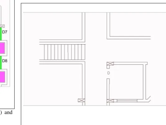
Figure 3: Part of a floor-plan showing a staircase, junction and corridors
3.1.4 Staircase / Ramp: A staircase or a ramp is a construc-tion used to bridge some vertical distance in a building. It is very similar to a corridor, the difference being it adds a height factor to the building. It is the only feature which has a vertical char-acteristic and thus usually acts as a connecting element between the floors. Figure 4 shows the staircase marked on the part of a floor-plan given in Figure 3.
The properties of this class of space
are-1. Geometry 2. Capacity
3. Openings : Two Entry/Exit points 4. State : blocked or clear
5. Vertical component
(a) Step height and number of steps (in case of staircase) (b) Slope and length (in case of ramp)
6. Impedance (Calculated based on the obstacles in the space)
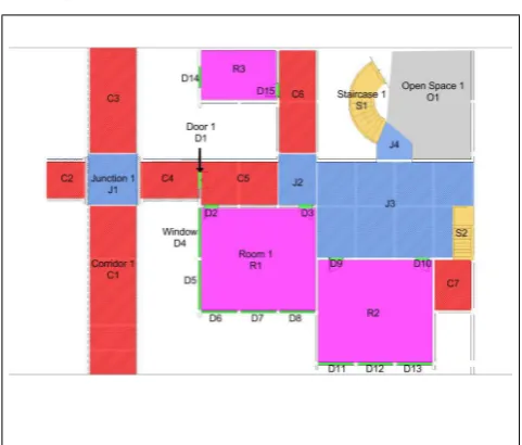
Figure 4: Spaces marked as staircase(yellow), junction(blue), room(pink), corridor(red) and doors/windows(green)
3.1.5 Open Space: We have defined open space as a space which is a safe space and usually lies outside or just around the building. It can be denoted as the final destination of the evacu-ation. So we can treat it as an exit or a place from where other rescue personnel can evacuate.
1. Capacity (holding) 2. Openings
3.1.6 Door / Window: These are the most common types of openings encountered in a building. While doors connect differ-ent spaces to each other, windows don’t exactly do that but they are considered in our model since in the case of emergency evac-uation they may be used as a means to get out.
Since a door or a window does not readily connect the spaces if it is locked or blocked so we have assigned a property of state to them which will determine whether they are open, closed, or blocked. Also a cost would be associated for each state change so the properties are defined to reflect the
same-1. Capacity : clearance capacity - number of people who can pass through at a time
2. Openings : connectivity (connecting which two spaces) 3. State : open, closed or blocked
4. Cost of changing the state (from closed or blocked to open)
An example of doors/windows marked can be seen in the Figure 2. They are represented as nodes in the network.
3.1.7 Special case of Room - Auditorium/Theatre/Big Hall:
If a room is very large and has a complex structure inside (as in the case of a movie theatre), then it can be broken down into mini-corridors, mini-junctions, mini-rooms etc. as traversing in it may be as complicated as traversing in a building itself.
4. CASE STUDY
For our case study we took one of the classroom buildings of our institute,International Institute of Information Technology - Hy-derabadin India, calledHimalaya. The Figure 5 shows a part of the floor-plan of the ground floor of the building. The rooms are represented in pink colour, corridors in red, junctions in blue, staircases/ramps in yellow and doors/windows in green. As can
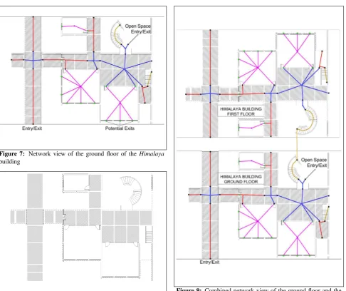
be seen in Figure 6, the corridor 5 (C5) and the junction 2 (J2) is made by breaking the geometry of the passage from the floor-plan. This is required when some complex geometries are en-countered. Figure 7 depicts the conversion of these classified fea-tures into a network, based on the definition given in this paper. While converting to a network, doors/windows or any openings in the space act as nodes.
Figure 8 depicts a part of the floor plan of the first floor of the Himalaya building. The combined network of both the floors can be seen in Figure 9. It also shows the staircase acting as the connecting element of the two floors.
Figure 5:Floor-plan of a part of the ground floor of theHimalaya building
Figure 6: Assigning classes to space in terms of the set of fea-tures
Using such a model, the paths in a building spanning multiple floors can be identified and the distances along these paths can be measured. In case of room, since we are storing the geometry of the features, the distance from the openings to any position inside the room (not necessarily the centroid) can be calculated. This will allow us to do a calculation for the worst case scenario by choosing a point inside the room at the maximum distance from the openings.
Class Properties
Static Dynamic
<geometry> <capacity> <openings> <impedance> <distance openings> <congestion> <state>
1 Room ✓ ✓ [<D>] ✓ List of distances
be-tween the openings and the centroid of the room
✘ ✘
2 Corridor ✓ ✓ [<D>,<C>,<J>,<O>,<S>] ✓ List of distances be-tween other openings and the corridor line
✓ ✘
3 Junction ✓ ✓ [<D>,<C>,<J>,<O>,<S>] ✓ List of distances be-tween the openings and the centroid of the junction
✓ ✘
4 Staircase/Ramp ✓ ✓ 2 (<D>,<C>,<J>,<O>,<S>) ✓ Distance between the two openings
✘ ✓
5 Open Space ✘ ✓ [<D>,<C>,<J>,<O>,<S>] ✘ ✘ ✘ ✘
6 Door/Window ✘ Clearance capacity
2 (<C>,<R>,<J>,<O>) ✘ ✘ ✘ ✓
Table 1: The set of features and the grammar of the defined properties.
Figure 7: Network view of the ground floor of the Himalaya building
Figure 8: Floor-plan of a part of the first floor of theHimalaya building
5. CONCLUSION AND FUTURE WORK
The model defined allows us to convert the geometry of a building into a more meaningful representation with spatial properties de-fined.We will be able to generate connected navigational graphs using just the space elements without any dependency on the data model. In such a model, an iterative search of the elements is not necessary since the properties of connectivity and continuity is
Figure 9: Combined network view of the ground floor and the first floor of theHimalayabuilding. The first floor is vertically flipped for better understanding of the network.
The model can be extended further to define new classes for other application scenarios. Future work will focus on automatic ex-traction of the space in terms of the defined semantic model from the popular data models like IFC and CityGML. Using the com-mon definition of the space, interoperability between these data models will also be explored.
REFERENCES
buildingSMART International Ltd., 2016. Ifc overview summary.
http://www.buildingsmart-tech.org/specifications/
ifc-overview.
Donkers, S., 2013. Automatic generation of CityGML LoD3 building models from IFC models. PhD thesis, TU Delft, Delft University of Technology.
El-Mekawy, M., ¨Ostman, A. and Shahzad, K., 2011. Towards in-teroperating CityGML and IFC building models: a unified model based approach. In:Advances in 3D Geo-Information Sciences, Springer, pp. 73–93.
Gr¨oger, G., Kolbe, T., Nagel, C. and H¨afele, K., 2012. OGC city geography markup language (CityGML) encoding standard, version 2.0, ogc doc no. 12-019.Open Geospatial Consortium.
Kemp, K. K. and Vckovski, A., 1998. Towards an ontology of fields. In:Third international conference on GeoComputation.
Mark, D. M., Egenhofer, M. J. and Hornsby, K., 1997. Formal models of commonsense geographic worlds. In: Report on the Specialist Meeting of Research Initiative, Vol. 21, pp. 97–2.
Mortari, F., Zlatanova, S., Liu, L. and Clementini, E., 2014. ”Im-proved Geometric Network Model”(IGNM): a novel approach for deriving connectivity graphs for indoor navigation.ISPRS Annals of the Photogrammetry, Remote Sensing and Spatial Information Sciences2(4), pp. 45.
OGC, 2016. What is bim about? http://www.
opengeospatial.org/ogc/markets-technologies/bim.
Taneja, S., Akinci, B., Garrett, J. H., Soibelman, L. and East, B., 2011. Transforming IFC-based building layout information into a geometric topology network for indoor navigation assistance. In:Computing in Civil Engineering, ASCE, pp. 315–322.