CONSTRUCTION OF A 3D MEASURABLE VIRTUAL REALITY ENVIRONMENT
BASED ON GROUND PANORAMIC IMAGES AND ORBITAL IMAGERY FOR
PLANETARY EXPLORATION APPLICATIONS
Kaichang Di*, Jian Liang, Zhaoqin Liu
Institute of Remote Sensing Applications, Chinese Academy of Sciences
P. O. Box 9718, Datun Rd, Chaoyang District, Beijing 100101, P.R.China
(kcdi, liangjian, liuzq)@irsa.ac.cn
Commission IV, WG IV/7
KEY WORDS: Planetary, Measurable Virtual Reality, Three-dimensional, Ground Panoramic Images, Orbital Imagery.
ABSTRACT:
This paper presents a method of constructing a measurable virtual reality environment based on ground (lander/rover) panoramic images and orbital imagery. Ground panoramic images acquired by a lander/rover at different azimuth and elevation angles are automatically registered, seamlessly mosaicked and projected onto a cylindrical surface. A specific function is developed for inverse calculation from the panorama back to the original images so that the 3D information associated with the original stereo images can be retrieved or computed. The three-dimensional measurable panorama is integrated into a globe viewer based on NASA World Wind. The techniques developed in this research can be used in visualization of and measuring the orbital and ground images for planetary exploration missions, especially rover missions.
1. INTRODUCTION
Planetary exploration usually consists of orbital and lander/rover missions. Orbital images map the planet globally and provide geometrical and spectral information for landing-site selection, precision landing, and various scientific researches. Ground (lander/rover) images provide more detailed information of the landing site for daily mission operations such as close-up investigation of scientific targets. Visualization of these orbital and ground images and their derived products is essential to support mission operations and scientific researches, as well as education and outreach.
In earth observation and GIS fields, virtual reality (VR) and virtual geographic environments (VGE) technologies have been utilized for various applications (Lin and Gong, 2001). The concept of measurable virtual reality (MVR) was proposed and implemented based on seamless stereo-orthoimage database with digital stereo-orthophoto partner technique (Li et al., 2002). The concept and application of digital measurable images (DMI) in digital earth and geospatial information service have also been exploited (Li et al., 2008, 2010). GIS technologies have also been used in planetary exploration researches and operations, e.g., the Planetary Interactive GIS on-the-Web Analyzable Database (PIGWAD) developed by U.S. Geological Survey (Hare and Tanaka, 2000) and the OSU Mars WebGIS developed by the Ohio State University (Li et al., 2006). Overall, VR and MVR technologies have not fully studied and applied in planetary exploration applications.
As one of the most popular earth viewers, Google Earth (http://www.google.com/earth/) has included Moon and Mars
orbital data, which enables users to fly anywhere on the Moon and Mars and view them from any view angles with multiple resolutions. Simple measuring functions such as length and heading are also provided. Panoramic images can be linked to the orbital images at locations where the panoramas were taken by lunar astronauts or Mars rovers. NASA World Wind (http://worldwind.arc.nasa.gov/), an open source earth viewer, has similar functions and includes more planets in the solar system. Overall, these viewers have very powerful and easy-to-use functions of viewing and browsing, but the measuring functions are limited, in particular, no measuring function is provided for panoramic images.
In this paper, we present a method of constructing a Measurable Virtual reality Environment (MVE) based on ground (lander/rover) panoramic images and orbital imagery. The MVE is implemented using ground panoramic images acquired by Spirit rover of the Mars Exploration Rover (MER) mission and HiRISE (High Resolution Imaging Science Experiment) orbital images of Mars. The technical details of the MVE construction method are given in the following sections.
2. CONCEPT OF MEASURABLE VIRTUAL REALITY ENVIRONMENT (MVE)
2.1 Concept of MVE
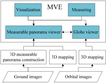
Figure 1 shows the conceptual diagram of the proposed MVE. Its core components include a panorama viewer and a globe viewer based on NASA World Wind. The three-dimensional (3D) measurable panoramas are constructed from ground stereo
*Corresponding author
images through registration, mosaicking and projection onto a cylindrical surface. In particular, in order to enable 3D measurement functionalities in the panorama viewer, a specific function is developed for inverse calculation from the panorama back to the original images. The globe viewer is a platform for visualization and measuring of DEMs and orthophotos derived from ground and orbital images through 3D mapping procedures. Rover paths are also included in the globe viewer. The two viewers are interlinked and can be switched from one to the other. The MVE allows a user to visualize the orbital and ground images and maps from overhead view or the rover’s view and measure 3D information easily.
Figure 1. Conceptual diagram of MVE
2.2 Data
In this study, we use ground images taken by Spirit rover’s Navcam (Navigation Camera) and Pancam (Panoramic Camera) and HiRISE orbital images covering the landing site of Spirit rover. The Navcam is a panchromatic stereo pair of engineering camera with 20 cm baseline separation (Alexander et al., 2006). The Pancam is a multispectral stereo pair of science cameras with 30 cm baseline separation. Both Navcam and Pancam are mounted on the camera bar, which can rotate ±90 degrees of elevation and 360 degrees of azimuth, enabling acquisition of panoramic images. The rover images have been pre-processed by the Jet Propulsion Laboratory (JPL) Multi-mission Image Processing Laboratory (MIPL) and products such as mosaics, linearized (epipolar) images, 3D coordinate data and range maps are also provided (Alexander et al., 2006). The derived 3D data sets, e.g., 3D coordinate data (XYL files) and range map (RNL files) are stored with the index of the left images of
the stereo pairs. The images and the associated 3D data can be downloaded from the MER Analyst’s Notebook website (http://an.rsl.wustl.edu/mer/mera/mera.htm), which is part of the Geosciences Node of the Planetary Data System (PDS). Figure 2 shows a pairs of linearized Pancam images.
HiRISE is a pushbroom sensor on board the Mars Reconn-aissance Orbiter. It has an unprecedented high spatial resolution of up to 0.25 m/pixel, resolving objects below a meter across (McEwen et al., 2007). HiRISE images can be downloaded from the HIRISE webpage (http://hirise.lpl.arizona.edu/) or from the PDS website (http://pds.jpl.nasa.gov/).
3. PANORAMA MOSAICKING
Automatic construction of large, high-resolution image mosaics is an active area of research in the fields of computer vision, image processing, and computer graphics (Szeliski and Shum, 1997). Though some panoramic mosaics of rover images are provided in PDS, we build our own panoramic mosaic from linearized Navcam and Pancam images so as to enable 3D measurement functionalities.
3.1 Image pre-processing
In many cases, the rover traversed and stopped on slopes. This resulted in slanted horizons in the images. As a pre-processing step, horizon correction is performed using the images’ exterior orientation parameters with the following equation:
⎩
⎨
⎧
+
=
′
−
=
′
κ
κ
κ
κ
cos
sin
sin
cos
y
x
y
y
x
x
where (x, y) are the image coordinates of the original images, (x′, y′) are the coordinates of the horizon corrected image, κ is the rotation angle around the optical axis. Figure 3 shows an example image before and after horizon correction.
Figure 3. Horizon correction
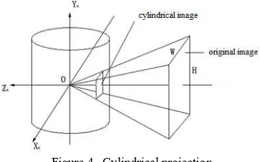
3.2 Cylindrical projection
There are three commonly used projections for panorama construction: cylindrical projection, spherical projection and cube projection. In this paper, we focus on the cylindrical panoramas because of their ease of construction and good geometric characteristics. If the camera focal length or field of view is known, each perspective image can be warped into International Archives of the Photogrammetry, Remote Sensing and Spatial Information Sciences, Volume XXXVIII-4/W25, 2011
Figure 4. Cylindrical projection
Figure 4 is an illustration of cylindrical projection, which allows 360 degree view of the environment. The cylindrical projection has the limitation of no representation at north pole and south pole. This doesn’t matter much for rover panoramic images because the images usually do not cover zenith and nadir.
3.3 Panorama stitching
Panorama stitching is based on the open source program Hugin with our new developments to incorporate the images’ exterior orientation parameters. Hugin is a cross-platform panorama photo stitching program developed by Pablo d'Angelo and others (http://hugin.sourceforge.net/). It is a GUI front-end for Helmut Dersch's Panorama Tools and Andrew Mihal's Enblend and Enfuse (Wikipedia, 2011a). The principle is using scale-invariant feature transform (Lowe, 2004) to detect feature points in the overlapping images taken from the same location and delete mismatched points by a RANSAC algorithm. Based on the matched feature points (tie points), the images are aligned and blended together to form a larger image. In order to ensure high geometric accuracy for seamless mosaicking, bundle adjustment is performed to find the optimal overall registration. Based on the bundle adjustment result, the panorama can be fully stitched, transformed and saved in a standard image format.
Figure 5. Mosaicked panorama
Figure 5 shows the panorama mosaicked by 81 single band linearized images of Spirit rover. The original images were acquired by Spirit’s Pancam from Sol 672 to 677 at three different elevation angles.
While panorama mosaicking is accomplished, the following parameters should be recorded in a project file to prepare for the inverse calculation from the panorama back to the original images: (1) Original image file path, image format, size, focal length, horizontal FOV, lens type; (2) Panoramic image size, image format, projection type; (3) Tie points in the original images.
4. VISUALIZATION AND MEASUREING IN MVE
Panorama visualization
The mosaicked panorama is a large image with cylindrical projection. A panorama viewer is developed to visualize the panorama based on Microsoft DirectX technology. A virtual camera is set at the middle of the cylinder; rotation around the center and vertical displacement can be controlled to achieve panoramic browsing. The viewer transforms the cylindrical projection of the panorama in the viewing window to perspective projection on the fly. Similar to QuickTime VR (Chen, 1995), the panorama viewer has the basic functions such as rotating and tilting the view, zooming in and out.
Measuring in panorama
The capability of measuring 3D information in the panorama viewer is one of our innovations. Since the 3D information is associated with the original rover images, the key technique to achieve a 3D measurable panorama is the inverse calculation from the panorama back to the original images. This process is divided into the following steps: mapping from a point on the panorama viewer to the two-dimensional panoramic image, then to the cylindrically projected image (single image), finally to the original image.
Calculation of projected coordinates: First, the hor-izontal FOV of each pixel in the panorama is calculated by
W
HFOV
ρ=
where W is the width of panorama, HFOV is the horizontal FOV of panorama which is usually 360 degrees. Suppose
I x
(
p,
y
p)
is a point in the panorama, thecorresp-onding point in the cylindrically projected single image
( ,
c c)
I x y
′
is calculated from the following formula:sin cos sin cos sin
sin sin cos
sin sin sin cos cos
sin cos cos rotation angles that construct rotation matrix.
4.2.2 Inverse cylindrical projection: While we get the projected point
I x y
′
( ,
c c)
, the next step is to compute the corresponding coordinates in the original imageI x y
′′
( ,
o o)
: International Archives of the Photogrammetry, Remote Sensing and Spatial Information Sciences, Volume XXXVIII-4/W25, 20112 2
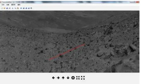
4.2.3 3D Measuring in panorama: As mentioned earlier, along with the original stereo images of the MER rovers, PDS also provides range data, slope data and 3D coordinates data. The data are stored corresponding to the linearized left images’ pixel coordinates. In the panorama viewer, the 3D information (such as ground location, elevation, distance to the rover, azimuth angle, slope etc.) of each pixel can be measured by clicking on the pixel and inverse computation. Not only a single point, but also a line can be measured in the panorama viewer. As show in Figures 6 and 7, once two endpoints of a line are determined, the elevation and slope profiles will be plotted. In a similar way, more 3D information can be retrieved and plotted.
Figure 6. Measuring a profile in the panorama
Figure 7. Elevation and slope profiles measured from the panorama
For those stereo images without 3D information available, the panorama viewer will locate the stereo pair and invoke a stereo measurement window to computer the 3D information through
the pixel in the panorama viewer. This on-the-fly 3D measuring function is realized by inverse calculation from the panorama to the original stereo images, stereo image matching with cross correlation and least squares matching, and space intersection for 3D position calculation. Similarly, elevation and slope profiles can be generated on-the-fly.
Figure 8. Stereo measurement window associated with the panorama viewer
5. INTERGRATION OF PANORAMA VIEWER AND GLOBE VIEWER
World Wind is an open source (released under the NOSA license) virtual globe developed by NASA and the open source community for use on personal computers. Apart from the Earth there are several globes in World Wind: Moon, Mars, Venus, Jupiter and SDSS (imagery of stars and galactics) (Wikipedia, 2011b). Users can interact with the selected planet by rotating it, tilting the view, and zooming in and out. Data in World Wind are managed by Extensible Markup Language (XML). It is convenient to add our own images, DEMs, orthophotos, rover path and other data.
Based on the stereo HiRISE images of the Spirit rover landing site, we produced a high resolution DEM and orthophoto and overlaid them on the Mars surface in World Wind. The 3D measurable panoramas are then integrated into World Wind with hotlinks to the HiRISE and rover orthophotos to construct the MVE. To accelerate the rendering speed in World Wind, the image data are organized by pyramids. At each level, the pyramid is cut into 512×512 pixel tiles to be compatible with World Wind. The path of rover was added by Keyhole Markup Language (KML) files which can be interpreted by World Wind.
(a) Full display of Mars in World Wind (b) Mars with HiRISE International Archives of the Photogrammetry, Remote Sensing and Spatial Information Sciences, Volume XXXVIII-4/W25, 2011
Figure 9 shows the interface of the globe viewer. With the integrated panorama viewer and globe viewer, orbital and ground images and derived 3D information can be visualized and measured from different view angles seamlessly.
6. SUMMARY
This paper presented a method of constructing a measurable virtual reality environment based on ground panoramic images and orbital imagery. An innovative measurable panorama technique was developed and the panorama viewer was integrated into a globe viewer to form the MVE, which allows for not only visualization but also 3D measuring of planetary images in a virtual environment.
More Mars data and lunar data will be processed and put into the MVE system for test and validation; relevant functions will be further improved. The techniques developed in this research can be used in visualization of and measuring the orbital and ground images for planetary exploration missions, especially rover missions.
ACKNOWLEDGEMENTS
Funding of this research by National Natural Science Foundation of China (40871202, 41002120) and the National High Technology Research and Development Program of China (2009AA12Z310) is acknowledged.
REFERENCES
Alexander, D.A., Deen, R.G.,Andres, P.M., Zamani, P., Mort-ensen, H.B., Chen, A.C., Cayanan, M.K., Hall, J.R., Klochko, V.S., Pariser, O., Stanley, C.L., Thompson, C.K., Yagi, G.M., 2006. Processing of Mars Exploration Rover imagery for science and operations planning. Journal of Geophysical Research – Planets. 111 (E2), E02S02.
Chen, S.E., 1995. QuickTime VR – an image-based approach to virtual environment navigation. Computer Graphics (SIGGR-APH’95), pp. 29–38.
Hare, T.M., and Tanaka, K.L., 2000. PIGWAD – New functi-onality for planetary GIS on the web. 31st Lunar and Planetary Science Conference, Abstract No. 1889.
Li, D., Wang, M. and Gong, J., 2002. Principle and Implement of Measurable Virtual Reality (MVR) Based on Seamless Stereo-orthoimage Database. The International Archives of the Photogrammetry, Remote Sensing and Spatial Information Sciences. vol. XXX IV, part no. 5/W3.
Li, R., Di, K., Wang, J., Niu, X., Agarwal, S., Brodayagina, E., Oberg, E., and Hwangbo, J.W., 2007. A WebGIS for Spatial Data Processing, Analysis, and Distribution for the MER 2003 Mission. Photogrammetric Engineering and Remote Sensing, Special Issue on Web and Wireless GIS, 73(6), pp. 671-680.
Li, D., Huang, J. and Shao, Z., 2008. Digital Earth with Digital Measurable Images. The International Archives of the Photogr-ammetry, Remote Sensing and Spatial Information Sciences. vol. XXXVII, part no. B4.
Li, D., and Shen, X., 2010. Geospatial Information Service Based on Digital Measurable Image - Take Image City Wuhan as an Example. Geo-Spatial Information Science. 13(2), pp. 79-84.
Lin, H., and Gong, J. 2001. Exploring Virtual Geographic Envi-ronments. Annals of GIS, 7(1), pp.1-7.
Lowe, D. G., 2004. Distinctive Image Features from Scale-Invariant Keypoints. International Journal of Computer Vision, 60(2), pp. 91-110.
McEwen, A.S., Eliason, E.M., Bergstrom, J.W., et al., 2007. Mars reconnaissance orbiter’s high-resolution imaging science experiment (HiRISE). Journal of Geophysical Research, 112, E05S02.
Szeliski, R., Shum, H., 1997. Creating full view panoramic image mosaics and texture-mapped models. SIGGRAPH '97 Proceedings of the 24th annual conference on Computer graphics and interactive techniques. Los Angeles, CA, USA, pp. 251-258.
Wikipedia, 2011a, Hugin (software), http://en.wikipedia.org/wi-ki/Hugin_%28software%29 (accessed 10 July. 2011)
Wikipedia, 2011b, NASA World Wind, http://en.wik-ipedia.org/wiki/World_Wind (accessed 10 July. 2011)