Christian Di Natali
, Student Member, IEEE
, Jacopo Buzzi, Nicol´o Garbin
, Student Member, IEEE
,
Marco Beccani
, Student Member, IEEE
, and Pietro Valdastri
, Senior Member, IEEE
Abstract—We propose local magnetic actuation (LMA) as an approach to robotic actuation for surgical instruments. An LMA actuation unit consists of a pair of diametrically magnetized single-dipole cylindrical magnets, working as magnetic gears across the abdominal wall. In this study, we developed a dynamic model for an LMA actuation unit by extending the theory proposed for coaxial magnetic gears. The dynamic model was used for closed-loop con-trol, and two alternative strategies—using either the angular veloc-ity at the motor or at the load as feedback parameter—were com-pared. The amount of mechanical power that can be transferred across the abdominal wall at different intermagnetic distances was also investigated. The proposed dynamic model presented a relative error below 7.5% in estimating the load torque from the system parameters. Both the strategies proposed for closed-loop control were effective in regulating the load speed with a relative error below 2% of the desired steady-state value. However, the load-side closed-loop control approach was more precise and allowed the system to transmit larger values of torque, showing, at the same time, less dependence from the angular velocity. In particular, an average value of 1.5 mN·m can be transferred at 7 cm, increasing up to 13.5 mN·m as the separation distance is reduced down to 2 cm. Given the constraints in diameter and volume for a surgi-cal instrument, the proposed approach allows for transferring a larger amount of mechanical power than what would be possible to achieve by embedding commercial dc motors.
Index Terms—Magnetic actuation, magnetic coupling, magnetic gear, medical robotics, servo control, two-inertia system.
Manuscript received May 12, 2014; revised November 24, 2014; accepted De-cember 12, 2014. Date of publication January 20, 2015; date of current version February 4, 2015. This paper was recommended for publication by Associate Editor A. Mueller and Editor B. J. Nelson upon evaluation of the reviewers’ comments. This work was supported by the National Science Foundation under Grant 1239355. Any opinions, findings, and conclusions or recommendations expressed in this material are those of the authors and do not necessarily reflect the views of the National Science Foundation.
C. Di Natali, N. Garbin, M. Beccani, P. Valdastri are with the Science and Technology of Robotics in Medicine (STORM) Labo-ratory, Department of Mechanical Engineering, Vanderbilt University, Nashville, TN 37235-1592 USA (e-mail: [email protected]; [email protected]; [email protected]; p.valdastri@ vanderbilt.edu).
J. Buzzi is with the DEIB (Dipartimento Elettronica Informazione Bioingegneria), Politecnico di Milano, Milano 20133, Italy (e-mail: jacopo. [email protected]).
This paper has supplementary downloadable material available at http://ieeexplore.ieee.org, provided by the author. The material consists of a video multimedia_attachment_1 with extension (.wmv), viewable with Win-dows Media Player, demonstrating the experimental platform used to assess either the magnetic spur gear model and the control strategies. In particu-lar, the video shows the step response for both the motor side closed-loop control and the load side closed-loop control strategies. Contact christian. [email protected] for further questions about this work.
Color versions of one or more of the figures in this paper are available online at http://ieeexplore.ieee.org.
Digital Object Identifier 10.1109/TRO.2014.2382851
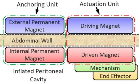
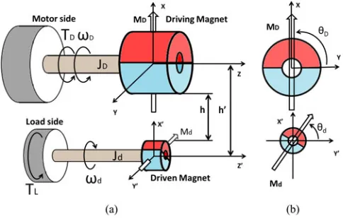
Fig. 1. Functional representation of an LMA-based robotic instrument cou-pled across the abdominal wall.
I. INTRODUCTION
M
AGNETIC coupling is one of the few physical phenom-ena capable of transmitting actuation forces across a physical barrier. This ability enables an entirely new paradigm for robotic instruments in minimally invasive surgery (MIS).In [1], the authors introduced the concept of local magnetic actuation (LMA), where mechanical power is transferred across the abdominal wall by magnetic coupling to drive a degree of freedom (DoF) of a laparoscopic robot. This approach prevents the need for embedded actuators and wired connections. As represented in Fig. 1, each LMA-based device is composed of at least one anchoring unit, plus an actuation unit per independent DoF. The anchoring unit is composed of an external and an internal permanent magnet, and its function is to support the instrument during surgery. The actuation unit is composed of an external driving permanent magnet and an internal driven permanent magnet. The driving magnet is connected to a motor and can be actuated independently, causing the actuation of the respective driven magnet, coupled across the abdominal wall. The driven magnet is used to actuate, through a mechanism, one DoF of the laparoscopic robot.
A possible implementation of LMA was proposed in [2], with two diametrically magnetized cylindrical permanent mag-nets working as magnetic spur gears across the abdominal wall. In this case, the external driving magnet in the actuation unit is axially rotated by a motor, and the driven magnet rotates accord-ingly. The mechanical power—in terms of rotational speed and load torque—transferred on the driven magnet can then be used to actuate a mechanism instead of an embedded motor. Consider-ing that the diameter of laparoscopic instruments is constrained by the inner lumen of the surgical port (typically 5–12 mm),
embed inside a laparoscopic robot. The mechanical continuity is also broken by using magnets coupled across the abdominal tissue overcoming workspace constraints and lack of triangula-tion due to cable-driven robots.
While magnetic anchoring was discussed in [1] and the theo-retical feasibility of driving a laparoscopic tool was shown in [2] via a static analysis, in this paper we focus on dynamic modeling and closed-loop control of a single LMA-actuated DoF. In addi-tion, we investigate the amount of mechanical power that can be transferred across the abdominal wall at different intermagnetic distances, and we compare the results with EM motors having a size similar to the internal driven magnet.
A. Clinical Motivation
Robotic surgery is currently a popular widely accepted clini-cal practice, as demonstrated by the over 2800 Intuitive Surgiclini-cal da Vinci platforms installed worldwide as of September 2013 [3]. Despite the wide availability of the da Vinci, robotics has yet to become the gold standard tool for general surgery, due its higher invasiveness compared with the laparoscopic approach [4]. The next generation of surgical robots should, therefore, aim to guarantee the same dexterity and performance as current robots, while reducing the access trauma.
A promising approach in this direction is represented by robotic platforms specifically developed for (or adapted to) Laparo-Endoscopic Single Site surgery [5]–[10]. Actuation for the several DoF may be external, by means of cables or rigid con-nection [5], [6]; internal, using on-board motors [7]–[9]; or hy-brid [10]. In any case, the mechanical continuity of the kinematic chain constrains the workspace proximally at the insertion point. Having the surgical instruments and the laparoscopic camera magnetically coupled across the abdominal wall would greatly enhance both freedom of operation and triangulation (i.e., the triangular positioning of the camera and surgical instruments in laparoscopy which mimics the positioning of the human head and arms [11]). Fully insertable magnetic surgical instruments were first proposed in [12]. These instruments are able to enter the abdominal cavity through the same single incision, without taking up port space during the operation. Each single surgical instrument is coupled with an independent external handheld magnet. The main drawback of this approach is in the low dex-terity and poor motion accuracy due to manual operation of the external magnets [13]. To overcome this limitation, mag-netic coupling can be used mainly for gross positioning, while on-board EM motors can be adopted for providing fine motion of the surgical end effector [9], [13], [14]. As previously men-tioned, however, the on-board actuators that can fit through a single tiny incision are very limited in power and do not al-low the performance of surgical tasks such as lifting an organ or following in real-time the surgeon’s movements at the mas-ter inmas-terface. Larger more powerful motors can be used at the
provided by a large EM motor—placed outside the patient—can be leveraged for actuating the internal mechanism [2].
B. Technical Contribution
Tetherless transmission of mechanical power between mag-netic field generators outside of the body and instruments within the body is gaining momentum in the surgical robotics commu-nity, as shown by the increasing number of platforms to drive wireless capsule endoscopes [15]–[20]. A similar approach to what is discussed in this paper has recently been proposed in [21], where a magnetic resonance scanner generates the driving magnetic field, imposing the rotation of a small ferromagnetic body around an axis. The mechanical power transferred with this approach is used to drive one DoF of a needle injection robot. While this approach recalls the principle of operation of EM motors—with an external source generating a rotating mag-netic field and an internal rotor following it—the LMA is more closely related to magnetic gears [22].
Previous work in the field of magnetic gears for industrial ap-plications suggests that a coaxial concentric topology with radial coupling (i.e., driving and driven magnetic systems mounted one inside the other as in [23]) would enable a more efficient power transmission than a coupling where the gears are rotating on parallel axes. This is due to a more homogeneous distribution of the attractive force around the main axis of each gear, as all the pole pairs are simultaneously involved in the transmission of mechanical power [24]. However, in the proposed applica-tion, this approach is unfeasible as the abdominal wall stands in between the driving and the driven units. A possible solution is then to adopt a parallel-axis radial coupling across the tissue, with the associated challenge of an asymmetric attracting force and the related vibrations.
As regards the number of pole pairs, a magnetic coupling based on single-dipole magnets allows maximization of the vol-ume of the magnetic material contributing to the torque trans-fer. Therefore, a parallel-axis radial coupling with single-dipole magnets seems to be the best solution for transmitting mechani-cal power to a device deep inside the human body. This approach was adopted in [25] for driving an implantable telescopic rod to correct skeletal deformities. While this study reported an inter-esting medical application, it did not address the challenges of achieving a servo control of the magnetic coupling.
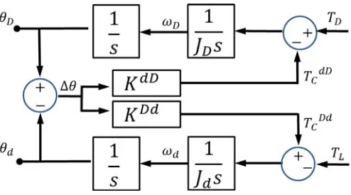
Fig. 2. Block diagram for the closed-loop control of an LMA actuation unit.
4 cm [27], we focus our analysis onhranging from 2 to 7 cm. Within this range, we model the dynamics of the LMA actuation unit, quantify the amount of mechanical power that can be trans-ferred, and investigate two alternative strategies for closing the control loop. The first strategy leverages the motor-side velocity as feedback parameter, as suggested in [26] for the servo control of coaxial magnetic gears. The alternative approach consists of using the load-side velocity acquired via magnetic field sensing.
II. CONTROLLING ALOCALMAGNETICACTUATIONUNIT
As represented in in Fig. 2, the closed-loop control diagram for a single LMA actuation unit is composed of the magnetic spur gear coupling, the actuator rotating the driving magnet, the sensors measuring the feedback parameters, and the controller driving the actuator.
Since the proposed LMA actuation strategy is intended to replace an onboard high speed/low torque rotational actuator, we aim to control the angular velocity at the load. As a feedback parameter, we investigate the use of either the driving or the driven magnet angular velocity, ωD or ωd, respectively. This
value is compared with the desired velocityωref, and the error
eωis fed to the controller that generates the appropriate voltage
inputVM to the actuator. The external actuator imposes a torque
TD at an angular velocity ωD to the magnetic gear system.
The mechanical power is transferred to the driven magnet via magnetic coupling, to overcome the load torqueTL, which is
seen as a disturbance to the system. As we use single-dipole magnets, the speed ratio between the driving and the driven magnets equals one. The proposed approach can be extended to multiple-dipole magnets by explicitly considering the ratio between the driven pole pairs and the driving pole pairs, as in [26]. The sensor feedback block measures in real timeωD
andωd and detects if the system has entered the pole-slipping
regime—the regime inherent to magnetic gears where control is lost due to torque overload [26], or excessive driving magnet acceleration that induces inertial reaction forces on the driven magnet [28]. A warning signal can be transmitted to a high level controller in case of pole slipping. As suggested in [26], the coupling can be reengaged by forcingωD at zero for a short
period before being reset to the original speed command input. Within this section, we first derive the open-loop dynamic model of the magnetic gear coupling (see Section II-A), then we describe the actuator model and the sensor feedback strategy (see Section II-B), and we conclude by proposing two alternative strategies to close the control loop (see Section II-C).
Fig. 3. (a) Schematic overview and (b) lateral cross section of the LMA actuation unit based on two diametrical magnetized cylindrical magnets.
A. Dynamic Model of the Magnetic Gear Coupling
A schematic diagram of the LMA actuation unit that is ana-lyzed in this study is represented in Fig. 3. The magnetic couple is composed of two cylindrical permanent magnets diametri-cally magnetized, having magnetization MD andMd for the
driving and the driven magnets, respectively. While we assume the two magnets having a single dipole each, we consider the general case where the two magnets are different in diameter and length.
An important assumption of our model is that the two mag-nets are lying on two parallel axes (i.e., z andz′), spaced by
a separation distanceh′. Note that we defineh′as the distance
between the two axes andhas the separation between the outer surfaces of the two magnets, as represented in Fig. 3(a). Re-ferring either tohorh′is equivalent, as the difference in their
values is constant. We also assume that abdominal tissue does not influence the magnetic coupling [29].
We defineJD andJd as the equivalent inertia at the driving
and at the driven magnet side, respectively, whileθD andθd
are the angular coordinates ofMD andMd as represented in
Fig. 3(b). The angular displacement of the drive train is denoted with∆θ=π−(|θD|+|θd|). As represented in Fig. 3(a), the
directions of rotation for the two magnets are opposite (i.e., a counterclockwise rotation of the driving magnet induces a clockwise rotation of the driven one).
The magnetic spur gear pair can be analytically described for differenthby modifying the equivalent model for a two-inertia mechanical system [30]. In conventional two-inertia servo-drive systems, the interconnecting drive shaft has a linear torsional stiffness K—unit of N·m/rad—that stays constant within the operating range. Therefore, the torque TC transmitted by the
prime mover to the load is a linear function of the angular displacement at the drive shaft. As introduced in [31], the torque transmitted across a radial magnetic coupling is not constant with ∆θ and can be described by a nonlinear trigonometric function
TC(∆θ) =TGsin(∆θ) (1)
whereTG is the maximum gear torque that can be transmitted
Fig. 4. Equivalent model of a magnetic spur gear pair with asymmetrical magnets.
volume and magnetization strength of the magnets and on their separation distanceh. In case the driving and the driven magnets differ in terms of volume or magnetization, the cross-coupling due to the magnetic field becomes asymmetrical, and two sep-arate nonlinear torque transfer functions must be considered, which are
TD d
C (∆θ, h) = TGD d(h) sin(∆θ) (2)
TCdD(∆θ, h) = TGdD(h) sin(∆θ) (3)
where (2) refers to the torque transferred from the driving to the driven magnet, while (3) refers to the torque transferred in the opposite direction.
The numerical values ofTD d
G andTGdD at differenthcan be
obtained by the static analysis and the finite element method (FEM) integration described in [1]. For a given magnetic gear pair considered at∆θ=π/2,TD d
G (h)andTGdD(h)can be well
approximated by exponential fits.
Referring to the equivalent model represented in Fig. 4, the dynamic behavior of the LMA actuation unit can be described by
The trigonometric expressions ofTD d
C andTCdD can be
lin-Beyond|∆θ|< π/2 of angular displacement, the magnetic coupling enters a pole-slipping regime [26], [32], resulting in a consequential loss of control. This typically happens when the torque TL required by the load overcomes the maximum
value of torque that can be transmitted over the magnetic cou-pling,TD d
G (h). For a reliable control of the driven magnet, pole
slipping must be prevented. This can be accomplished by mon-itoring in real time∆θwith the method suggested in the next section.
The block diagram representing the open-loop system— shown in Fig. 5—can be derived by combining (4)–(7).
Fig. 5. Block diagram of the open-loop magnetic gear system.
Fig. 6. Dynamic model of the EM direct current (dc) motor with current monitoring.
In no-load conditions, the transfer functions relating the driv-ing torque to the drivdriv-ing and the driven angular velocities are given by
where the antiresonantωa and the resonantω0 frequencies are, respectively, given by
B. Actuator Model and Sensor Feedback
1) Actuator Model: In this study, we use an EM dc motor with current monitoring to drive the external magnet in the LMA actuation unit. The motor dynamic model—schematically represented in Fig. 6—considers
VM =KMωD+RtotiM +L
d
dtiM (11)
whereVM is the voltage applied to the motor,KM is the
Fig. 7. Angular position (θD andθd), angular speed (ωD andωd), angular displacement of the drive train (∆θ), and its time derivative (∆ω) are obtained through direct measurement of the magnetic field (BD andBd) generated by the driving and the driven magnets along the vertical direction.
termRtot includes both the motor and the current monitor re-sistances,RM andRcur respectively.
The motor torque TD, fed to the magnetic gear system, is
derived by monitoring the motor current as
TD =KT qiM (12)
whereKT q is the motor torque constant.
Defining δV as δV =VM −KMωD, the transfer function
relating the motor torqueTD toδV in the Laplace domain is
TD
δV =
KT q
L(Rtot/L+s).
(13)
2) Sensor Feedback: Previous work on magnetic gear servo control [26], [28] focused on motor-side sensing, as load-side feedback sensors may be prohibitive to use in certain applica-tions, such as off-shore wind turbines or all-electric automotive power trains. In case of surgical instruments, the constraints in-troduced by embedding feedback sensors on the load side are mainly related to sterilization and tethering. As for sterilization, low-temperature techniques can be adopted, in case the sen-sors cannot withstand the high temperature commonly used for steam sterilization (i.e., 132◦C). Regarding tethering, a wired connection would be the most reliable option to acquire the data from the on-board sensors. This may be an advantage in terms of usability, as it can facilitate the retrieval of the instrument from the abdominal cavity once the surgery is over.
In this study, we investigate both motor-side and load-side sensing strategies by taking advantage of a pair of magnetic field sensors (MFS). The motor-side sensor is placed next to the driving magnet, whereas the load-side sensor is placed close to the driven magnet (for the physical implementation, refer to Section III-A).
The block diagram in Fig. 7 shows how the signals acquired by the two MFS are used to derive the driving and the driven magnet angular positionsθD andθd, the angular velocitiesωD andωd,
the angular displacement of the drive train ∆θ, and its time derivative∆ω. Referring to Fig. 3, the component alongxof the magnetic field generated by the driving magnetBDis acquired
by the motor-side MFS, while the load-side MFS acquires the component along −x′ of the magnetic field generated by the
driven magnet,Bd. As the two magnets spin,BDandBdcan be
described by two cosine functions [1]. The magnetic field values are normalized, obtaininguD orud, and the angular derivatives
δuDandδud are calculated. The inverse of the tangent function
is applied to (uD,δuD) and to (ud,δud) to deriveθD andθd,
Fig. 8. Motor-side speed control system with PI controller.
respectively. Angular velocitiesωDandωdare then obtained by
the time derivative ofθD andθd, respectively.
C. Closing the Control Loop
Having both motor-side and load-side sensing available, we investigate and compare two alternative strategies to achieve closed-loop control of the angular velocityωref. Both controllers are designed to work within a range of intermagnetic separation distanceshfrom 2 to 7 cm. Therefore, the controllers parame-ters are chosen in order to ensure controllability in the range of analysis which includes population range of abdominal thick-ness.
1) Motor-Side Closed-Loop Control: When a motor-side control strategy is adopted, the driven part of the actuator may be seen as a disturbance. In our approach, similar to [26] and [30], we explicitly consider the effect of coupling in the control loop, and we adopt a standard proportional-integral (PI) con-troller fed with the motor-side angular velocityωD. The block
diagram of the closed-loop system is shown in Fig. 8. In this figure,Kp is the proportional feedback coefficient, whileKI is
the integral feedback coefficient.
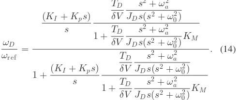
The closed-loop transfer function from the reference input to the motor speed is given by
ωD
2) Load-Side Closed-Loop Control: An alternative tech-nique consists of closing the control loop on the load-side an-gular speed ωd. This approach allows for a direct tracking of
Fig. 9. Load-side speed control system with the custom controller fed byωd.
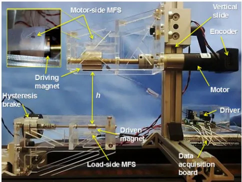
Fig. 10. Picture of the experimental platform. The upper left inset shows the placement of the MFS next to the driving magnet.
voltage inputVM is
VM
whereKc is the gain of the closed-loop controller,ω1 andω2 represent natural angular frequencies, and ζ1 and ζ2 denote damping coefficients.
The block diagram for the load-side speed control is shown in Fig. 9. The closed-loop transfer function from the reference input to the load speed is given by
ωd
III. MODELVALIDATION ANDEXPERIMENTALASSESSMENT A. Experimental Platform
The experimental platform designed to validate the LMA con-trol is represented in Fig. 10. An EM dc motor was used to spin the driving magnet, whereas the driven magnet was connected to a hysteresis brake. The motor-side assembly was mounted
Fig. 11. FEM estimations of the maximum transmissible torque functions and their exponential fittings for different intermagnetic distances.
on a vertical slide that allowed adjustment of the intermagnetic distanceh.
The dc motor (2342-024CR, Faulhaber, Germany) has a nom-inal voltage of 24 V, embeds a 1:3.7 planetary gearhead, and can provide a maximum torque of 60 mN·m at a maximum speed of 1900 r/min. A two-channel optical encoder (HEDS 5500, Avago Technologies, USA) with 96 counts per revolution was connected to the motor and provided the reference for assessing the feedback strategy described in Section II-B.
The driving magnet (K&J Magnetics, Inc., Pennsylvania, USA) is made of NdFeB and has a cylindrical shape (25.4 mm in both diameter and length) with diametrical magnetization (N42 grade, 1.32 T in magnetic remanence). The driven magnet has the same features, but smaller dimensions (9.5 mm in both diameter and length). The diameter of the driven magnet was selected to fit a laparoscopic device that can enter the abdominal cavity through a 12-mm surgical port. Given the selected pair of magnets,TD d
G andTGdD forhranging from 2 to 7 cm were
estimated by FEM integration (COMSOL Multiphysics, USA). Two two-term exponential models were used to fit the FEM data, obtaining
wherehhas the unit of meters. The fitting functions were ob-tained with the Curve Fitting Toolbox (MATLAB, Mathworks, USA), by setting the confidence level at 98%. The two fitting functions are represented together with the FEM estimations in Fig. 11.
The hysteresis brake (H3, Placid Industries, USA) was used to impose on the driven magnet a controllableTL. Two MFS
platform resulted inJD =8.9×10⁻⁶kg·m2 andJd =0.46
×10−6kg·m2, respectively.
A data acquisition board (DAQ USB-6211, National Instru-ments, USA) was used to collect the data from the MFS at 500 Hz and to control both the motor and the hysteresis brake via a custom driver. Regarding the operation of the motor, the current drained is monitored across a 10 Ωbuffered resistor
Rcur. The hysteresis brake was also controlled in voltage, while the drained current was monitored via a second buffered resistor. The user interface, developed in C++, allowed the user to select one of the two control strategies and to setωrefup to 1900 r/min andTL from 0.5 to 25 mN·m.
B. Dynamic Model Validation
The first step of validation focused on assessing the sensor feedback strategy reported in Section II-B, as this was used for all the experiments that follow. In particular, we compared
ωD as measured by the encoder with the value estimated by
implementing the algorithm in Fig. 7. This test was performed forωD=[500, 700, 900, 1100, 1300, 1500] r/min, showing an
average error of7.28±2.82r/min. We can reasonably assume a similar uncertainty in reconstructingωd and∆ω.
The next step consisted of validating the dynamic model of the magnetic gear coupling for different separation distancesh, driving angular velocitiesωD, and applying load torquesTL. A
single experiment consisted of increasingTL, while driving the
external magnet at a constant speedωDand maintaining a fixed
intermagnetic distanceh. As soon as the system entered in the pole-slipping regime, the experiment was ended. The intermag-netic distancehwas varied from 2 to 7 cm in steps increments of 1 cm, whileωDwas increased from 500 to 1500 r/min in steps
increments of 200 r/min. The motor-side closed-loop control described in Section II-C1 was adopted to guarantee a con-stant ωD, as TL was increased. Once a trial was started, the
platform increased the voltage driving the hysteresis brake in 0.15 V increments every 0.2 s, resulting in an exponential in-crease ofTL over time. The event of pole slipping was detected
by monitoringθd as measured by the sensor-side MFS. In
par-ticular, whenθdwas stalling around a limited number of angular
positions, the algorithm assumed that the system was entered in the pole-slipping regime. In that case, the motor was stopped, the hysteresis brake was released, and the trial was considered over.
For each experiment, the data recorded forθD,θd, andTD
were used together with platform-specific parameters (i.e.,JD,
Jd,T˜GD d,T˜GdD) to estimateTL. The dynamic model forTLwas
derived by combining (4) and (5) and integrating over time, thus obtaining
TL(t) =Jd∆θ(t)
1 ∆t2 +
2
π
˜
TdD G
JD
+ 2
π
˜
TD d G
Jd
− Jd JD
TD(t).
(19)
Fig. 12. Comparison between the estimated and the reference load torque for h= 4 cm andωD = 1000 r/min. The unloaded, loaded, and pole-slipping regimes are highlighted by the dashed vertical lines.
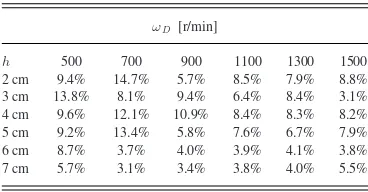
TABLE I
MEANRELATIVEERRORS INTLESTIMATION ATDIFFERENTVELOCITIES AND INTERMAGNETICDISTANCESWITHIN THELOADEDREGIME
ωD [r/min]
h 500 700 900 1100 1300 1500 2 cm 9.4% 14.7% 5.7% 8.5% 7.9% 8.8% 3 cm 13.8% 8.1% 9.4% 6.4% 8.4% 3.1% 4 cm 9.6% 12.1% 10.9% 8.4% 8.3% 8.2% 5 cm 9.2% 13.4% 5.8% 7.6% 6.7% 7.9% 6 cm 8.7% 3.7% 4.0% 3.9% 4.1% 3.8% 7 cm 5.7% 3.1% 3.4% 3.8% 4.0% 5.5%
The reference value for TL was obtained by measuring the
current drained by the hysteresis brake and deriving the torque applied to the driven magnet from its calibration curve.
A typical plot for a single experiment at h= 4 cm and
ωD = 1000 r/min is represented in Fig. 12. Here, three
dif-ferent regimes can be observed. In unloaded conditions, angular oscillations at the driven magnet were induced by the low inertia, combined with the nonlinear elastic coupling of the magnetic link. In this regime, reconstruction of TL by the model was
noisy. AsTL increased, the amplitude of oscillations decreased
significantly, and the model allowed for a reliable real-time es-timation of the load torque. As expected, the system entered the pole-slipping regime as TL overcame the maximum value of
torque that can be transmitted over the magnetic coupling. Five experiments were repeated for each combination ofh
and ωD, and the estimation errors were averaged. The mean
relative errors in estimating TL at different velocities and
in-termagnetic distances are reported in Table I. Over the entire range of distances and velocities tested, the mean relative er-ror was7.1±2.3%, while the mean absolute error was0.18±
Fig. 13. Bode amplitude diagrams for the (a) motor-side and (b) load-side open-loop transfer functions for six discrete values of h (i.e., h= [2,3,4,5,6,7]cm).
C. Closed-Loop Control Validation
Once the dynamic model was experimentally validated, we studied how variations in hwere affecting the harmonic be-havior of the two open-loop transfer functions in (8) and (9). Therefore, we plotted the two Bode diagrams for six discrete values ofh(i.e.,h= [2,3,4,5,6,7]cm). From the amplitude plots in Fig. 13(a), we can observe that both the resonant and the antiresonant peaks in the motor-side transfer function migrate to lower frequencies ashincreases, spanning less than a decade. In particular,ω0 =156 rad/s ath=2 cm, decreasing toω0 = 45 rad/s ath=7 cm. A similar behavior can be observed for the resonant peaks in the load-side transfer function, the amplitude of which is plotted in Fig. 13(b). From the two Bode amplitude plots, it is relevant to emphasize that the singularities of the sys-tem and the range of their migration ashchanges from 2 to 7 cm are within the interval of angular velocities investigated in this work (i.e., 500 r/min corresponds to 52 rad/s, while 1500 r/min corresponds to 157 rad/s). In determining the parameters for the two closed-loop controllers, we optimized the system response forh= [2...7]cm (i.e., the condition in which singularities oc-cur at lower frequencies), and we experimentally investigated whether this choice could guarantee controllability in the entire range ofhtested.
The proportional and integral coefficients for the motor-side closed-loop control were determined via the PID Tuning function of the Control System Toolbox (MATLAB, Math-Works, USA), obtainingKP =52.42×10⁻³V·s/rad andKI=
5.90 V/rad. Simulated step responses for h= [2,3,4,5,6,7] cm are reported in Fig. 14(a), showing an overshoot that ranges from 11.4% to 10.8% and a settling time from 100 to 180 ms.
As regards the load-side control strategy, the parameters for the custom controller were also tuned for the range of
analy-Fig. 14. Simulated step response for the (a) motor-side and (b) load-side closed-loop control for six discrete values ofh(i.e.,h= [2,3,4,5,6,7]cm).
sis (h∈[2,7]cm), resulting in the following constants Kc =
3.4×10³ V/rad, ω1 =1.6×10⁻⁴ rad/s,ω2 =5.5× 10⁻⁶ rad/s, ζ1 = 0.68, and ζ2 = 1. Simulated step responses for
h= [2,3,4,5,6,7]cm are reported in Fig. 14(b), showing no relevant overshoot and a settling time of 200 ms for all the distances investigated.
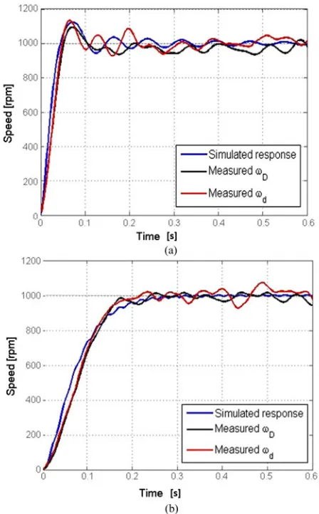
A comparison between the simulated and the experimental step response is reported in Fig. 15(a) for the motor-side closed-loop control, and in Fig. 15(b) for load-side closed-closed-loop control. Experiments were performed withωref =1000 r/min ath= 4 cm in unloaded conditions, and bothωDandωdwere recorded.
The video showing the experimental set-up and the step response trials is attached as multimedia extension 1.
As regards the step response for the motor-side closed-loop control in Fig. 15(a), the measuredωD and ωd presented an
overshoot of 11.2% and 11.6%, respectively. These results were comparable with the overshoot obtained in the simulated response. Concerning the steady state,ωD presented an average
value of 998 ±23 r/min, while the average ωd was 1032 ±
32 r/min. As expected, no significant overshoot was observed in the load-side closed-loop control step response (14.b), and the settling time ofωdwas comparable with the model predictions.
The average regime value was 990±18 r/min forωD, and 1006
Fig. 15. (a) Simulated and experimental step response ath=4 cm for motor-side closed-loop control. Both the measuredωD andωd are reported in the figure. (b) Simulated and experimental step response ath=4 cm for load-side closed-loop control. Both the measuredωD andωdare reported in the figure.
By comparing the results, we can observe that the load-side controller allowed achievement of a more precise regulation of the averageωd than the motor-side approach. Both controllers
showed a ripple in the regulated speed of about 3% of the regime value. This effect was mainly due to the absence of a load connected to the driven magnet, as the system was working in the unloaded regime.
D. Load Rejection and Torque Transmission
The presence of a load torque applied at the gear train in-duces variations in the parameters of the system, as it affects the equivalent inertia at the driven shaft. In particular, system characteristics such as the resonant and antiresonant frequencies are both influenced by variations inJd. The experimental trials
reported in this section aim to assess both closed-loop control strategies under different loading conditions.
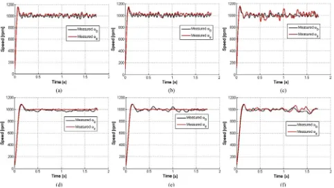
First, a set of speed step responses were measured by setting
TLat 20%, 50%, and 80% ofT˜GD d(h). The trials were performed
by imposingωref =1000 r/min ath=4 cm, and the results for the motor-side closed-loop control are reported in Fig. 16. The steady-state error forωd adopting the motor-side closed-loop
was 2±3 r/min forTL at 20% ofT˜GD d[see Fig. 16(d)], 1±6
r/min forTLat 50% ofT˜GD d[see Fig. 16(e)], and 0.3±13 r/min
forTL at 80% ofT˜GD d[see Fig. 16(f)].
From the results reported in Fig. 16, we can observe that the load-side control strategy was more effective in forcing the system to reach the desiredωref, although an overshoot of 8% of the steady state appeared as the load was applied. The load-side closed-loop control step response presented a ripple forωd
within the 1% of the steady-state value, while the motor-side closed-loop control showed a ripple up to 4%. From the plots, we can observe that both strategies showed an increase in the ripple with the appliedTL, as the system was moving toward
the pole-slipping regime.
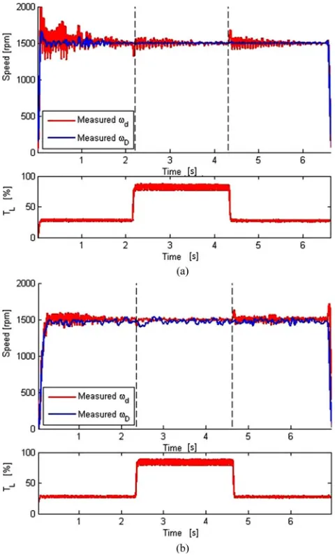
Load rejection experiments were then performed for both the control strategies at h= 4 cm, and the results obtained are represented in Fig. 17. The reference speedωrefwas set to 1500 r/min, whileTL was initially set to 28% ofT˜GD d, then increased
up to 85% ofT˜D d
G for about 2.5 s before resetting it to the initial
value. While the load was at the 85% ofT˜D d
G , the average error
and the ripple for ωd were 6 ±31 r/min for the motor-side
closed-loop control [see Fig. 17(a)] and 3 ±12 r/min for the load-side closed-loop control [see Fig. 17(b)].
Both control strategies allowed rejection of the effect of a load variation without pole slipping. By analyzing Fig. 17(a) in more detail, we can observe residual damped oscillations inωd
for more than 1 s after the variation in the load is applied. These oscillations are due to the nonlinear torsional spring behavior of the coupling and are further amplified by the effect of an inertia ratio well below the unit [33] (i.e., in the proposed drive train, modeled as a two-inertia system, the inertia ratio in unloaded conditions isJd/JD =0.056). As shown in Fig. 17(b), the
cus-tom controller implemented for the load-side strategy, providing a lag compensation, was effective in eliminating these oscilla-tions inωd by modulatingωD.
A final test was performed to evaluate the mechanical power that can be transmitted by an LMA actuation unit at differ-ent intermagnetic distances. Using the motor-side closed-loop control, the maximum torque at the loadTm ax
L before entering
the pole-slipping regime was experimentally measured forωref ranging from 600 to 1700 r/min at different separation distances (i.e.,h= [2,3,4,5,6,7]cm). Each trial was repeated ten times, and the results are reported in Fig. 18(a).
Fig. 16. Experimental step responses for (a), (b), (c) motor-side closed-loop control and (d), (e), (f) load-side closed-loop control withTL at (a) and (d) 20%, (b) and (e) 50%, and (c) and (f) 80% ofT˜D d
G . Experiments were performed ath=4 cm imposing aωre f=1000 r/min. Each plot shows the measured values for
bothωD andωd.
The same test was repeated for the load-side closed-loop control, and the results are reported in Fig. 18(b). By compar-ing the plots in Fig. 18(a) and 18(b), we can conclude that the load-side controller enables a larger torque to be transmitted be-fore entering the pole-slipping regime. In particular, an average value of 1.5 mN·m can be transferred at 7 cm, increasing up to 13.5 mN·m as the separation distance is reduced down to 2 cm. In addition, the effect of the resonant peaks is less evident when using the load-side closed-loop control, which provides a value ofTm ax
L that is almost constant withωref for hlarger than 3 cm.
E. Performance Evaluation of Local Magnetic Actuation
In analyzing the overall performance that an LMA actuation unit can achieve, we consider adopting the load-side closed-loop control as it provided a better performance when compared with the motor-side approach. In Fig. 19 and Table II, we compare the maximum torque that can be transferred at different intermag-netic distances—same data as Fig. 18(b)—with the theoretical limit provided by FEM estimation. With the proposed dynamic modeling and control strategy, we are able to transfer an aver-age of 86.2% of the theoretical value of maximum torque. This deviation is due to the adoption of a linear model forTD d
C and
TdD
C in (6) and (7), respectively. For large angular
displace-ments, which are expected as the load torque brings the system toward the pole-slipping regime, a linear model in (6) and (7) is far from being accurate and needs to be replaced by a nonlinear equivalent.
From Fig. 19, it is also interesting to observe that the stan-dard deviation in Tm ax
L is larger at smaller distances. This
may be explained by considering other magnetic effects that are present in the system, but have not been included in the dynamic model, such as the vertical attraction force between the driving and the driven magnets that varies as the magnets spin [34].
As previously mentioned, an LMA actuation unit can be used instead of an onboard EM motor for driving a DoF of a laparo-scopic robot. For the sake of comparison, in Table III, we listed off-the-shelf EM motors that have a diameter comparable with the driven magnet used in this study.
Thanks to a speed ratio equals one, the maximum speed that can be achieved at the driven shaft with the LMA approach corresponds to the maximum speed of the external EM motor. As the external motor is not as constrained in size as a motor to be embedded on board, a faster actuator than those listed in Table III can be adopted. As for the stall torque, we can assume for the LMA approach the values ofTm ax
L (h)reported
in Table II. As represented in Fig. 18(b), we can consider the stall torque to be constant as the speed increases. Considering that the driven magnet used in this study was 9.5 mm in both diameter and length, we can conclude that the LMA approach can provide a volumetric power density that is well above any of the motors listed in Table III at any of the intermagnetic distances investigated.
Fig. 17. (a) Experimental load rejection responses for motor-side closed-loop control and (b) load-side closed-loop control. The profile ofTL, moving from 28% ofT˜GD dto 85% ofT˜GD dand back to its initial value, is represented below the speed plot. Experiments were performed ath=4 cm settingωre f=1500
r/min. Each plot shows the measured values for bothωdandωD and the trend of the applied load torque.
wireless link [44] without increasing dramatically the size of the surgical tool.
IV. CONCLUSION ANDFUTUREWORK
In this study, we demonstrated the feasibility of controlling a parallel-axis radial coupling with asymmetrical single-dipole magnets within a range of intermagnetic separation distances compatible with the abdominal thickness in humans. This par-ticular kind of magnetic coupling, referred as LMA actuation unit, can be used in designing robotic surgical instruments to transfer mechanical power from outside the body of a patient to a laparoscopic instrument within. Given the constraints in diameter and volume for a surgical instrument, the proposed approach allows for transferring a larger amount of mechanical power than what is possible to achieve by embedding actuators on board.
Fig. 18. Maximum torque at the load before entering the pole-slipping regime, measured using (a) the motor-side and (b) the load-side controller at different speeds and separation distances. Each data point is the result of ten independent trials.
Fig. 19. Maximum torque at the load before entering the pole-slipping regime as a function of the intermagnetic distance. Theoretical value
˜
TGD d and experimental data obtained by using the load-side closed-loop control,Tm a x
Distance[cm ]
MAX Torque [mN·m] 2 3 4 5 6 7
ModelT˜D d
G (h) 15.95 8.01 4.58 2.90 1.96 1.38
ExperimentTm a x
L 13.63 6.82 3.98 2.52 1.68 1.20
Efficiency % 85.4 85.2 87.0 86.8 85.5 87.3
TABLE III
OFF-THE-SHELFEM MOTORSCOMPARABLEWITH THESIZE OF THEDRIVEN MAGNETUSED INTHISPAPER
Model Diameter Length Max Speed Stall Torque Reference Namiki-SBL04 4 mm 13.8 mm 7000 r/min 0.13 mN·m [35] Faulhaber-1016 10 mm 16 mm 18400 r/min 0.87 mN·m [36] Faulhaber-1024 10 mm 24 mm 14700 r/min 2.89 mN·m [37] Maxon-DCX10L 10 mm 25 mm 12000 r/min 5.42 mN·m [38] Faulhaber-1219 12 mm 19 mm 16200 r/min 0.96 mN·m [39] Faulhaber-1224 12 mm 24 mm 13800 r/min 3.62 mN·m [40] Precision-NC110 12 mm 12.5 mm 10000 r/min 0.50 mN·m [41] Precision-MC112 12 mm 20 mm 9500 r/min 1.50 mN·m [42] Namiki-SCL12 12.5 mm 32 mm 13750 r/min 3.71 mN·m [43]
The solution we propose for the servo control of an LMA actu-ation unit takes advantage of a dynamic model of the coupling, adapted from a two-inertia servo-drive system, and a sensing strategy based on Hall effect MFSs placed next to the driving and the driven magnets. In this study, we also compare two alternative approaches in closing the control loop. The first, referred to as motor-side closed-loop control, uses the angu-lar velocity of the driving magnet as the feedback parameter and has the advantage of relying only on sensors placed on the motor-side of the coupling, thus outside the patient’s body. The alternative approach, referred to as load-side closed-loop control, directly controls the angular velocity at the load and requires a Hall effect sensor to be placed inside the surgical instrument. The two approaches were assessed and compared in terms of step response, load rejection, and maximum torque that can be transmitted at different speeds and intermagnetic distances.
From the experimental results, we can conclude that the dy-namic model we developed presented a relative error below 7.5% in estimating the load torque from the system parameters, while the sensing strategy based on Hall effect sensors had an average error below 1% in reconstructing the shaft speed. Con-cerning closed-loop control, both the strategies were effective in regulating the load speed with a relative error below 2% of the desired steady-state value. When comparing the two approaches, the load-side closed-loop control achieved a better performance, both in terms of steady-state error (below 0.2%) and ripple in the angular velocity (below 1%). In addition, the load-side
closed-robots, a number of challenges still remain for future research.
The first direction of future work is improving the robustness of the control. As mentioned in Section III-E, a nonlinear ap-proach must be adopted to increase the amount of transmitted torque closer to its theoretical limit. Predictive control, sug-gested in [28] for coaxial magnetic gears, can be a viable solu-tion. To reduce the oscillations inωdfurther, a digital notch-filter
compensator, as suggested in [45], can be adopted. In addition, the model needs to be extended to a situation in which the two magnets spin on axes that are not fixed, nor parallel, as analyzed in [18]. Horizontal and vertical vibrations must be considered, as they will be present during laparoscopic surgery. Vertical at-traction force between the driving and the driven magnets must be included in the model.
When designing an LMA-based surgical instrument as repre-sented in Fig. 1, the actuation module must provide controlled motion for a DoF, while the anchoring module should support the weight of the instrument and the vertical forces applied during tissue interaction. Overshoot in the speed at the driven magnet may occur in some conditions and must be taken into account when designing the mechanism that goes from the ro-tating shaft to the surgical end effector [34]. If the surgical robot needs more than one DoF, a number of LMA actuation mod-ules will have to interact within the same confined space. Mag-netic cross-coupling among LMA anchoring and actuation units may become an issue in this case. As the magnetic force and torque, respectively, decrease with the inverse of the fourth and third power of the intermagnetic distance, we plan to address this challenge by properly spacing the magnets on board the surgical instrument. Shielding with ferromagnetic or diamag-netic material can also be considered to address this problem. The model of the system would then be extended to include cross-coupling and to provide a tool for designing appropriate shielding between modules.
As discussed in Section II, the system can enter in the pole-slipping regime as a consequence of torque overload. As sug-gested in [26], the coupling can be reengaged by stopping the motor rotation for a short period and then resetting the input command. However, if the load is still above the maximum torque that can be transmitted, this strategy will be ineffec-tive. A potential solution to this problem consists of controlling the vertical position of the external driving magnet so that h
Extension Type Description
1 Video Step response of both motor and load side closed-loop controls REFERENCES
[1] C. Di Natali, T. Ranzani, M. Simi, A. Menciassi, and P. Valdastri, “Trans-abdominal active magnetic linkage for robotic surgery: Concept definition and model assessment,” inProc. IEEE Int. Conf. Robot. Autom., 2012, pp. 695–700.
[2] C. Di Natali, and P. Valdastri, “Remote active magnetic actuation for a single-access surgical robotic manipulator,”Int. J. Comput. Assisted Radiol. Surg., vol. 7, pp. S169–S171, 2012.
[3] Intuitive Surgical. (2014). [Online]. Available: www.intuitivesurgical.com [4] S. Maeso, M. Reza, J. Mayol, J. Blasco, M. Guerra, E. Andradas, and M. Plana, “Efficacy of the Da Vinci surgical system in abdominal surgery com-pared with that of laparoscopy: A systematic review and meta-analysis,”
Ann. Surg., vol. 252, no. 2, pp. 254–262, 2010.
[5] G. Haber, M. White, R. Autorino, P. Escobar, M. Kroh, S. Chalikonda, R. Khanna, S. Forest, B. Yang, F. Altunrende, R. J. Stein, and J. H. Kaouk, “Novel robotic Da Vinci instruments for laparoendoscopic single-site surgery,”Urology, vol. 76, no. 6, pp. 1279–1282, 2010.
[6] J. Ding, R. E. Goldman, K. Xu, P. K. Allen, D. L. Fowler, and N. Simaan, “Design and coordination kinematics of an insertable robotic effectors platform for single-port access surgery,”IEEE/ASME Trans. Mechatron-ics, vol. 18, no. 5, pp. 1612–1624, Oct. 2013.
[7] A. Lehman, N. Wood, S. Farritor, M. Goede, and D. Oleynikov, “Dex-terous miniature robot for advanced minimally invasive surgery,”Surg. Endoscopy, vol. 25, pp. 119–123, 2010.
[8] J. Shang, C. J. Payne, J. Clark, D. P. Noonan, K.-W. Kwok, A. Darzi, and G.-Z. Yang, “Design of a multitasking robotic platform with flexible arms and articulated head for minimally invasive surgery,” inProc. IEEE/RSJ Int. Conf. Intell. Robots Syst., 2012, pp. 1988–1993.
[9] G. Tortora, P. Dario, and A. Menciassi, “Array of robots augmenting the kinematics of endocavitary surgery,”IEEE/ASME Trans. Mechatronics, vol. 19, no. 6, pp. 1821–1829, Dec. 2014.
[10] M. Piccigallo, U. Scarfogliero, C. Quaglia, G. Petroni, P. Valdastri, A. Menciassi, and P. Dario, “Design of a novel bimanual robotic system for single-port laparoscopy,”IEEE/ASME Trans. Mechatronics, vol. 15, no. 6, pp. 871–878, Dec. 2010.
[11] S. Best and J. Cadeddu, “Development of magnetic anchoring and guid-ance systems for minimally invasive surgery,”Indian J. Urol., vol. 26, no. 3, pp. 418–422, 2010.
[12] I. Zeltser, R. Bergs, R. Fernandez, L. Baker, R. Eberhart, and J. Cadeddu, “Single trocar laparoscopic nephrectomy using magnetic anchoring and guidance system in the porcine model,” J. Urol., vol. 178, no. 1, pp. 288–291, 2007.
[13] M. Simi, R. Pickens, A. Menciassi, S. D. Herrell, and P. Valdastri, “Fine tilt tuning of a laparoscopic camera by local magnetic actuation: Two-port nephrectomy experience on human cadavers,”Surg. Innov., vol. 20, no. 4, pp. 385–394, 2013.
[14] A. Lehman, J. Dumpert, N. Wood, L. Redden, A. Visty, S. Farritor, B. Var-nell, and D. Oleynikov, “Natural orifice cholecystectomy using a miniature robot,”Surg. Endoscopy, vol. 23, pp. 260–266, 2009.
[15] G. Ciuti, P. Valdastri, A. Menciassi, and P. Dario, “Robotic magnetic steering and locomotion of capsule endoscope for diagnostic and surgical endoluminal procedures,”Robotica, vol. 28, no. 2, pp. 199–207, 2010. [16] J. F. Rey, H. Ogata, N. Hosoe, K. Ohtsuka, N. Ogata, K. Ikeda, H. Aihara,
I. Pangtay, T. Hibi, S. Kudo, and H. Tajiri, “Blinded nonrandomized com-parative study of gastric examination with a magnetically guided capsule endoscope and standard videoendoscope,”Gastrointestinal Endoscopy, vol. 75, no. 2, pp. 373–381, 2012.
[17] J. Keller, C. Fibbe, F. Volke, J. Gerber, A. C. Mosse, M. Reimann-Zawadzki, E. Rabinovitz, P. Layer, D. Schmitt, V. Andresen, U. Rosien, and P. Swain, “Inspection of the human stomach using remote-controlled capsule endoscopy: A feasibility study in healthy volunteers (with videos),”Gastrointestinal Endoscopy, vol. 73, no. 1, pp. 22–28, 2011.
actuated soft capsule endoscope,”IEEE Trans. Robot., vol. 28, no. 1, pp. 183–194, Feb. 2012.
[20] C. Di Natali, M. Beccani, K. L. Obstein, and P. Valdastri, “A wireless plat-form for in vivo measurement of resistant properties of the gastrointestinal tract,”Physiol. Meas., vol. 35, pp. 1197–1214, 2014.
[21] P. Vartholomeos, C. Bergeles, L. Qin, and P. E. Dupont, “An MRI-powered and controlled actuator technology for tetherless robotic interventions,”
Int. J. Robot. Res., vol. 32, no. 13, pp. 1536–1552, 2013.
[22] K. Ikuta, M. Shunichi, and A. Suguro, “Non-contact magnetic gear for micro transmission mechanism,” inProc. IEEE Micro Electro Mech. Syst., 1991, pp. 125–130.
[23] X. Li, K.-T. Chau, M. Cheng, and W. Hua, “Comparison of magnetic-geared permanent magnet machines,”Progr. Electromagn. Res., vol. 133, pp. 177–198, 2013.
[24] K. Atallah and D. Howe, “A novel high-performance magnetic gear,”
IEEE Trans. Magn., vol. 37, no. 4, pp. 2844–2846, Jul. 2001.
[25] J. A. Liu, M. Etemadi, J. A. Heller, D. Kwiat, R. Fetcher, M. R. Har-rison, and S. Roy, “Roboimplant ii: Development of a noninvasive con-troller/actuator for wireless correction of orthopedic structural deformi-ties,”ASME J. Med. Devices, vol. 6, pp. 031006-1–031006-5, 2012. [26] R. Montague, C. Bingham, and K. Atallah, “Servo control of magnetic
gears,”IEEE/ASME Trans. Mechatronics, vol. 17, no. 2, pp. 269–278, Apr. 2012.
[27] S. L. Best, R. Bergs, M. Gedeon, J. Paramo, R. Fernandez, J. A. Cadeddu, and D. J. Scott, “Maximizing coupling strength of magnetically anchored surgical instruments: How thick can we go?”Surg. Endoscopy, vol. 25, no. 1, pp. 153–159, 2011.
[28] R. Montague and C. Bingham, “Nonlinear control of magnetically-geared drive-trains,”Int. J. Autom. Comput., vol. 10, no. 4, pp. 319–326, 2013. [29] Non-ionizing radiation frequencies. (2014). [Online]. Available:
http://www.icnirp.org/en/frequencies/index.html
[30] G. Zhang and J. Furusho, “Speed control of two-inertia system by PI/PID control,”IEEE Trans. Ind. Electron., vol. 47, no. 3, pp. 603–609, Jun. 2000.
[31] E. Furlani, “A two-dimensional analysis for the coupling of magnetic gears,”IEEE Trans. Magn., vol. 33, no. 3, pp. 2317–2321, May 1997. [32] R. G. Montague, C. Bingham, and K. Atallah, “Magnetic gear pole-slip
prevention using explicit model predictive control,”IEEE/ASME Trans. Mechatronics, vol. 18, no. 3, pp. 1535–1543, Oct. 2013.
[33] G. Zhang, “Speed control of two-inertia system by pi/pid control,”IEEE Trans. Ind. Electron., vol. 47, no. 3, pp. 603–609, Jun. 2000.
[34] N. Garbin, C. Di Natali, J. Buzzi, E. De Momi, and P. Valdastri, “La-paroscopic tissue retractor based on local magnetic actuation,”J. Med. Devices, vol. 9, no. 011005, pp. 1–10, 2015.
[35] SBL04-0829PG0443. Namiki Precision Jewel Co. (2015). [Online]. Avail-able:www.namiki.net
[36] 1016-012G. Faulhaber Miniature Drive Systems. (2015). [Online]. Avail-able:www.faulhaber.com
[37] 1024-012S. Faulhaber Miniature Drive Systems. (2015).[Online]. Avail-able:www.faulhaber.com
[38] DCX10L. Maxon Motor. (2015). [Online]. Available:http://www. maxonmotor.com/
[39] 1219-012G. Faulhaber Miniature Drive Systems. (2015). [Online]. Avail-able:www.faulhaber.com
[40] 1224-012SR. Faulhaber Miniature Drive Systems. (2015). [Online]. Avail-able:www.faulhaber.com
[41] Nano Core 110-001. Precision Microdrivers. (2015). [Online]. Available:
www.precisionmicrodrives.com
[42] Micro Core 112-001. Precision Microdrivers. (2015). [Online]. Available:
www.precisionmicrodrives.com
[43] SCL12-3003. Namiki Precision Jewel Co. (2015). [Online]. Available:
www.namiki.net
[44] M. Beccani, E. Susilo, C. Di Natali and P. Valdastri. SMAC–A modular open source architecture for medical capsule robots.Int. J. Adv. Robot. Syst., 2014, vol. 11, no. 188, doi: 10.5772/59505
[45] S. N. Vukosavic and M. R. Stojic, “Suppression of torsional oscillations in a high-performance speed servo drive,”IEEE Trans. Ind. Electron., vol. 45, no. 1, pp. 108–117, Feb. 1998.
In 2011 he joined Institute of BioRobotics, Scuola Superiore Sant’Anna, Pisa, as a Research Assistant working on magnetic coupling and teleoperated mag-netic navigation. He is a Member of the Science and Technology of Robotics in Medicine Laboratory, Vanderbilt University, Nashville, TN, USA. He is actively involved in the design of advanced magnetic coupling for surgery and endoscopy, controlled mecha-tronic platforms, and magnetic localization.
Jacopo Buzzireceived the B.S. and M.S. degrees in biomedical engineering from Politecnico of Mi-lan, MiMi-lan, Italy, in 2012 and 2014, respectively. He is currently working toward the Ph.D. degree in biomedical engineering with Politecnico of Milan in robotic-assisted surgery, with a particular interest in developing new devices for neurosurgery.
In 2013 he joined for six months the Science and Technology of Robotics in Medicine Labora-tory, Vanderbilt University, Nashville, TN, USA. He would like to thank the collaboration between the NearLab and the STORM for this.
Nicolo Garbin(S’14) received the B.S. and M.S. de-grees in biomedical engineering from Politecnico of Milano, Milan, Italy, in 2011 and 2014, respectively. He is currently working toward the Ph.D. degree in mechanical engineering with Vanderbilt University, Nashville, TN, USA.
He is a Member of the Science and Technology of Robotics in Medicine Laboratory, and he is actively involved in the design of magnetic mechanism for surgical robots and new technology for laparoscopic surgery.
stitute of BioRobotics, Scuola Superiore Sant’Anna, Pisa. He is a Member of the Science and Technology of Robotics in Medicine Laboratory, Vanderbilt Uni-versity, Nashville, TN, USA, and his research inter-ests include miniaturized real-time embedded system design for wireless robotic capsular endoscopy and robotic surgery.
Pietro Valdastri(M’05–SM’13) received the Mas-ter’s (Hons.) degree in electronic engineering from University of Pisa, Pisa, Italy, in 2002 and the Ph.D. degree in biomedical engineering from Scuola Supe-riore Sant’Anna di Pisa (SSSA), Pisa, Italy.
![Fig. 13.Bode amplitude diagrams for the (a) motor-side and (b) load-side open-loop transfer functions for six discrete values of h (i.e., h =[2, 3, 4, 5, 6, 7] cm).](https://thumb-ap.123doks.com/thumbv2/123dok/3123977.1728053/8.594.58.278.63.301/bode-amplitude-diagrams-motor-transfer-functions-discrete-values.webp)