Design of Novel Yagi Aperture Antennas for Indoor TV
Reception using Low Cost Materials
Sofian Hamid
Department of Electrical Engineering, Faculty of Science and Technology, University of Al Azhar Indonesia, Jl. Sisingamangaraja, Jakarta, 12110
E-mail: [email protected]
Abstract – Most commercial Yagi antennas for TV reception are built based on wires. These Yagi wire-antennas are commonly used as outdoor antennas due to their size and weight properties. In this paper, novel light weight Yagi aperture antennas are introduced. Two prototypes had been built by using low cost materials such as aluminum (insects) screen, cylinder can, aluminum foil, and styrofoam. The antennas worked at the TV band and have gains around 9.7 – 13.5 dBi comparable to the outdoor Yagi wire antennas. Due to their lightweight and smaller dimension nature, they were suitable for used as indoor TV antennas. The antennas had also unique property due to the use of Styrofoam. They were portable, easy to construct and deconstruct.
Keywords – antenna, yagi, wideband, indoor,
lightweight
I. INTRODUCTION
agi-Uda antenna, or simply Yagi antenna, has been very popular used as TV outdoor antennas. It is invented by Japanese researchers, Shintaro Uda and Hidetsugu Yagi in 1926 [1]. The structure is simple. It consists of a reflector, driven element, and one or more directors. At TV broadcasting band, Yagi antennas are commonly implemented by using wires while at higher frequencies (GHz range) Yagi antennas sometimes fabricated by using PCB.
Typical wire-type Yagi antennas have quite large dimension around 100 cm x 60 cm x 40 cm and weight 2-4 kg (where the boom’s weight contributes the most). These are some reasons why Yagi antennas are commonly placed at outdoor. Of course, another reason is to get better TV signal reception. In this paper, we developed two
aperture-type Yagi antennas for TV broadcasting reception that have following properties: lightweight, smaller dimension (than the conventional Yagi antennas), high gain, wideband, portable and low cost. The antennas are built in modular fashion, make them easy to construct and deconstruct. Due to their simplicity in the fabrication, probably most people can build them given their dimension.
II. BASIC THEORY
Yagi antenna has an end-fire radiation pattern, which is a directive radiation pattern towards certain direction (usually we orientate this antenna to the direction of the TV transmitter). It has a simple configuration, consists of three parts: reflector, driven element and one or more directors [1-6]. Its configuration is shown in the figure below,
Figure 1. Yagi antenna structure[1]
Reflector is the longest (biggest) element that has a special function to reflect the received electromagnetic waves to the direction of driven element. It has an inductive reactance. We only need to use single reflector since additional reflector does not increase the antenna gain significantly.
The next element is the driven element. This is the heart of Yagi antenna. The operation frequency of Yagi antenna is determined by this element. In commercial Yagi antenna, the driven element usually has a half-wave dipole or folded dipole structure. If a half-wave dipole is used, then at its center frequency, it has a good match with the coaxial cable (75 Ohm). But if we use thin wire as the dipole element, then this matching condition will not last for wider band frequencies. In another way, folded dipole which is designed based on thin-wire has high input impedance near 300 Ohm. To match with the coaxial cable, then the distance between the reflector and the driven element should be reduced. This in turns will give more coupling and reduce the input impedance of the folded dipole. The typical distance between the reflector and the dipole structure driven element is 0.15 – 0.25 . The length of the driven element itself is usually 10% shorter than the reflector.
The third element is director. The more the directors we use, the higher the gain. But the increase is not linear. Its length is usually 10-20% shorter than the driven element. Director has capacitive reactance, which can decrease the inductive effect of reflector. The distance between director and the driven element is usually 0.25 – 0.35 .
III.RESEARCH METHOD
Before designing our prototypes, we conducted performance study on commercial Yagi antennas. The important parameters are physical structure, impedance bandwidth, gain, and radiation patterns. Based on these studies, we observe that the main limitation of commercial Yagi antennas are their excessive weight due to the use of metal boom and narrow bandwidth due to the use of dipole wire as the driven element.
We seek solution to overcome these problems by designing Yagi antennas, made of lightweight materials such as aluminum screen, Styrofoam, and a very thin thin aluminum plate. Instead of using dipole wire as the driven elements, we used large hollow cylindrical-dipole for the first prototype and planar folded dipole for the second prototype.
Simulation is needed to investigate whether our design fulfills the main goals of achieving wider band and lighter weight. Following this step, fabrication is performed to test the antennas
performance in a realistic radio propagation environment.
Figure 2. The structure of Prototype I
Figure 3. S-parameter magnitude of Prototype I
From Fig. 3, Prototype I works from 460 MHz to 930 MHz (normalized to 75 Ohm). It has a wider bandwidth than the wire-type Yagi antennas since the driven element is made of two cans which could be assumed as a thick cylindrical half-wave dipole. Thick dipole has wider bandwidth than thin dipole.
The radiation pattern is directive as can be seen below
Figure 4. Radiation pattern of Prototype I at 600 MHz, 700 MHz, and 800 MHz frequencies
Prototype II is designed with the goal to have a higher gain Yagi antenna. The reflector size is increased to be 40 cm x 30 cm. The driven element is changed to be a planar folded dipole structure and then more directors are added. Prototype II has seven arrays directors. It has a closer spacing between the reflector and the driven element, between the driven element and the director, and between the director arrays to obtain the input
impedance on the driven element close to 75 Ohm. The structure is shown on the figure below,
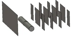
Figure 5. The structure of Prototype II
The planar folded dipole as the driven element has a size of 24 cm x 30 cm. It has two slots; horizontal slot which has a 12 cm x 4 cm dimension and vertical slot which has a 1.8 cm x 13 cm. The coaxial feeding is connected to the middle of the vertical slot.
Each array of directors consists of three columns of elements where each column has four elements. The dimension of the element is 10 cm x 6 cm. Since there are 7 arrays of directors, in total we have 7 x 3 x 4 elements = 84 elements. The spacing between the reflector and the driven element is 10 cm while the spacing between the driven element to the first array of directors is 8 cm. The spacing among the arrays is 6 cm and the spacing among the elements in vertical direction is 2 cm. The total size of Prototype II is 60 cm x 40 cm x 30 cm. Compared to Prototype I, Prototype II is bigger in the height direction. In the length and width direction, it is basically the same. The advantage of Prototype II is on the smaller spacing to give more coupling (to reduce the input impedance) to the planar folded dipole.
The simulated S-parameter magnitude is shown below,
Figure 6. The S-parameter magnitude of Prototype II (c) f = 800 MHz
directivity = 11.1 dBi
(a) f = 600 MHz
directivity = 9.7 dBi
From Fig. 6, Prototype II works from 420 MHz to 980 MHz (normalized to 75 Ohm). It has a wider band than Prototype I.
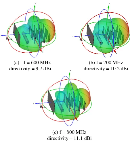
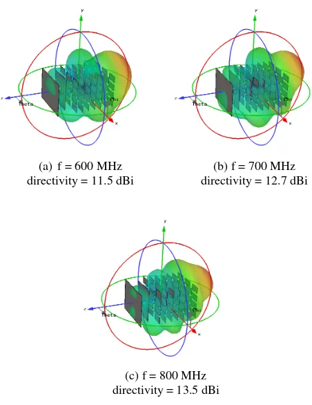
Since we use bigger reflector and more directors in Prototype II, the radiation pattern is more directive as seen on the figure below.
Figure 7. Radiation pattern of Prototype II at 600 MHz, 700 MHz, and 800 MHz frequencies
Compared to Prototype I, this antenna has a higher gain of about 2 dB.
4.2 Practical Implementation
The most interesting part in the design of antenna is the implementation or fabrication. In implementing Prototype I, we use a thin aluminum screen as the conductor for the reflector and directors. The driven element is implemented by using two cans made of aluminum plate. All these conductors are backed by Styrofoam with a thickness of 1.3 cm, make it modular. Special backed is created on the base of the antenna where we put two pieces of Styrofoam, forming the foundation for the antenna with a dimension of 60 cm x 40 cm x 2.6 cm.
The aluminum screen is attached to the Styrofoam by using transparent adhesive tape. The connection
between Styrofoam is created by using toothpick made of bamboo makes it flexible for construction and de-construction. The realized prototype I is shown below.
Figure 8. The realized prototype I
In the realization of Prototype II, we change the half-wave dipole with a planar folded dipole. It is created by using the aluminum screen. The material for the directors is the aluminum foil. Again, to attach the aluminum screen and aluminum foil to the Styrofoam, we use transparent adhesive tape. Below is the realization of Prototype II.
Figure 9. The realized prototype II
As seen on Fig. 9, the size of Prototype II is bigger than Prototype I in the height direction. The increase in the height direction contributes to the increase of its directivity. But compared to the outdoor Yagi antenna, this antenna is still smaller and far lighter. The total implementation cost for each prototype (without cable and connector) is less than $ 2. Prototype I and II have been tested directly to the TV. The performances of these indoor Yagi aperture antennas are similar to the commercial outdoor Yagi antennas and even for certain channels, these antennas perform better.
(a)f = 600 MHz directivity = 11.5 dBi
(b) f = 700 MHz directivity = 12.7 dBi
V. CONCLUSION
Novel Yagi aperture antennas have been designed and built by using low cost materials. They covered all TV bands and had interesting properties: lightweight, smaller (than outdoor Yagi wire antennas), low cost, directive pattern, and easy to construct and de-construct. Due to these properties, these antennas were suitable and flexible for indoor use.
The bandwidth of the antennas is greatly influenced by the shape and geometry of the driven elements. To increase the gain, we can use larger reflector and add more directors as they are used in the development of prototype II. Future works to achieve higher directivity would be done by optimizing the size and the shape of the director elements using metamaterial concepts.
REFERENCE
[1] C. A. Balanis, Antenna Theory: Analysis and Design, 3rd edition, John Wiley & Sons, Inc., 2005. [2] Gary C.-Y. Chen, K.K.-M. Chan, K. Rambabu, Miniaturized Yagi Class of Antennas for GSM, WLAN, and WiMAX Application, IEEE Transactions on Consumer Electronics, Vol. 56, No. 3, August 2010.
[3] S.H. Sedighy, A.R. Mallahzadeh, M. Soleimani, J. Rashed-Mohassel, Optimization of Printed Yagi Antenna using Invasive Weed Optimization, IEEE Antennas and Wireless Letters, Vol. 9, 2010. [4] Jari Holopainen, Outi Kivekas, Clemens Icheln,
Pertti Vainikainen, Internal Broadband Antennas for Digital Television Receiver in Mobile Terminals, IEEETranscation on Antennas and Propagation, Vol. 58, No. 10, October 2010. [5] Rui Guan, Xiaomiao Zhang, Li Jin, Zhen Zhang,
Weixi Zhou, A Compact Multi-Folded Patch Antenna for UWB Application at the UHF Band, Proceedings of International Symposium of Signals, Systems and Electronics, 2010.
![Figure 1. Yagi antenna structure[1]](https://thumb-ap.123doks.com/thumbv2/123dok/2725387.1676973/1.595.317.539.540.634/figure-yagi-antenna-structure.webp)