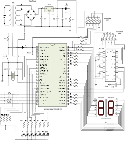
LAMPIRAN A
GAMBAR RANGKAIAN KESELURUHAN
LAMPIRAN B DAFTAR KOMPONEN
NO KOMPONEN NILAI /
10 Mikrokontroler PIC16F877 1 U1
LAMPIRAN C
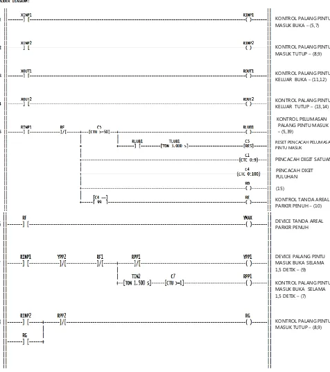
GAMBAR PROGRAM DAN STATUS INPUT OUPTUT
KONTROL PALANG PINTU MASUK BUKA – (5,7)
KONTROL PALANG PINTU MASUK TUTUP – (8,9)
KONTROL PALANG PINTU KELUAR BUKA – (11,12)
KONTROL PALANG PINTU KELUAR TUTUP – (13,14)
KONTROL PELUMASAN PALANG PINTU MASUK
– (5,39)
RESET PENCACAH PELUMASAN PINTU MASUK
PENCACAH DIGIT SATUAN
KONTROL TANDA AREAL PARKIR PENUH – (10) DEVICE TANDA AREAL PARKIR PENUH
DEVICE PALANG PINTU MASUK BUKA SELAMA 1,5 DETIK – (9)
KONTROL PALANG PINTU MASUK BUKA SELAMA 1,5 DETIK – (7) PENCACAH DIGIT PULUHAN
KONTROL PALANG PINTU MASUK TUTUP – (8,9)
DEVICE PALANG PINTU MASUK TUTUP SELAMA 1,5 DETIK - (7)
KONTROL AREAL PARKIR PENUH – (5,6,10)
KUNCI PINTU MASUK SAAT AREAL PARKIR PENUH-(7)
KONTROL PELUMASAN PALANG PINTU KELUAR – (11,40)
RESET PENCACAH PELU – MASAN PINTU KELUAR
PENCACAH SATUAN NAIK
RESET TANDA PARKIR PENUH – (10,16)
PENCACAH PULUHAN NAIK
KUNCI PINTU KELUAR SAAT NILAI COUNTER 99 ATAU SAAT AREAL PAKIR KOSONG TOTAL – (15)
DEVICE PALANG PINTU KELUAR BUKA SELAMA 1,5 DETIK – (14) KONTROL PALANG PINTU KELUAR BUKA SELAMA 1,5 DETIK – (12)
KONTROL PALANG PINTU KELUAR TUTUP – (14)
DEVICE PALANG PINTU KELUAR TUTUP SELAMA 1,5 DETIK – (12)
KUNCI PINTU KELUAR SAAT NILAI COUNTER 99 / PARKIR KOSONG –(11,15)
RESET COUTER C2
KONTROL ANGKA 8 DIGIT SATUAN – (18,38)
KONTROL ANGKA 7 DIGIT SATUAN – (38)
KONTROL ANGKA 5 DIGIT SATUAN – (38)
KONTROL ANGKA 4 DIGIT SATUAN – (38)
KONTROL ANGKA 3 DIGIT SATUAN – (38)
KONTROL ANGKA 6 DIGIT SATUAN – (38)
KONTROL ANGKA 2 DIGIT SATUAN – (38)
KONTROL ANGKA 1 DIGIT SATUAN – (38)
(12)
RESET PENCACAH DIGIT SATUAN
RESET PENCACAH DIGIT PULUHAN
KONTROL ANGKA 9 DIGIT PULUHAN – (38)
KONTROL ANGKA 8 DIGIT PULUHAN – (38)
KONTROL ANGKA 7 DIGIT PULUHAN – (38)
KONTROL ANGKA 6 DIGIT PULUHAN – (38)
KONTROL ANGKA 5 DIGIT PULUHAN – (38)
KONTROL ANGKA 0 DIGIT SATUAN – (17,18,38)
KONTROL ANGKA 4 DIGIT PULUHAN – (38)
KONTROL ANGKA 3 DIGIT PULUHAN – (38)
KONTROL ANGKA 2 DIGIT PULUHAN – (38)
KONTROL ANGKA 1 DIGIT PULUHAN – (38)
SEVEN SEGMENT A DIGIT SATUAN
SEVEN SEGMENT B DIGIT SATUAN
SEVEN SEGMENT C DIGIT SATUAN
SEVEN SEGMENT D DIGIT SATUAN
SEVEN SEGMENT E DIGIT SATUAN
SEVEN SEGMENT F DIGIT SATUAN
SEVEN SEGMENT G DIGIT SATUAN
SEVEN SEGMENT A DIGIT PULUHAN
SEVEN SEGMENT B DIGIT PULUHAN
SEVEN SEGMENT C DIGIT PULUHAN
SEVEN SEGMENT D DIGIT PULUHAN
SEVEN SEGMENT E DIGIT PULUHAN
SEVEN SEGMENT F DIGIT PULUHAN
SEVEN SEGMENT G DIGIT PULUHAN
DEVICE LUBRICATION
PINTU MASUK
DEVICE LUBRICATION
LAMPIRAN D
DATA SHEET MIKROKONTROLER PIC16F877
DAT
LAMPIR
TA SHEET
RAN E
TIC MAX 2232
LAMPIRAN F
LAMPIRAN G
LITERATUR IN CIRCUIT SERIAL PROGRAMMING
How to program a PIC 12Fxxx/16Fxxx
These PICs are programmed using a proprietary serial protocol. So you can't connect them directly to any "usual" interface. Fortunately, the timing requirements are rather lax. This gives the possibility to use some pins of a parallel or serial port of the PC to generate the programming sequence by
software.
Besides the operating voltage, three further signals are necessary: the programming voltage Vpp (about 13V) and the programming Clock (clk = PGC = ICSPCLK) and Data (data = PGD = ICSPDAT).
Since most PICs tolerate a programming voltage Vpp
somewhat below the specification, one can take advantage of the ±12V signal levels of the serial port of a Desktop PC and "burn" a PIC without the need for an extra power supply.
The level conversion can be done with a few components.
However, this simple circuit has its limitations and allows only reading and programming the PIC. There is no guarantee that it works with all controllers, since it does not meet all programming specifications.
(Board layout (inverted), Placing)
See below how to connect the programming signals to the PIC.
In-circuit programming of a PIC
ICSP offers the possibility to program the microcontroller within the application circuit. This is especially beneficial in class room or developing environments, where repetitive change between programming the PIC and testing the circuit occurs. It not only avoids risks when moving the PIC between different sockets – like bending the pins or
To be able to use ICSP neither the circuit must disturb the programming signals nor the programming signals should affect the circuit.
The main programming conditions are:
1. The programming voltage Vpp applied at /MCLR should switch between zero and 13 volts within a few microseconds.
2. The clock and data signals must reach near rail-to-rail levels within one microsecond.
3. Some PICs use a pin (RB3 or RB4) as PGM signal to offer Low Voltage Programming (LVP). This pin must stay Low while programming.
4. Some PICs require that the programming voltage Vpp is applied before the operating voltage Vdd. In this case Vdd must be operated by the programmer module.
The simplest way to fulfil the first two conditions is, not to use the corresponding pins within the application circuit. If you
also want to use the debugger, this is a must.
Recommendations:
Don't connect active circuits to /MCLR.
If /MCLR is used to reset the PIC, there should be a
resistor greater than 56kΩ between /MCLR and Vdd. It may be combined with a small capacitor of less than 100 pF to GND (Vss).
There must not be any
inductive or capacitive load on the programming signal pins. You may connect a high-impedance circuit (>10kΩ), e.g., a key.
When the operating voltage Vdd is operated by the programmer module, eventually you must isolate the Vdd pin of the PIC from the rest of the application circuit during programming. This may be the case, if the application circuit
o contains its own voltage regulator for Vdd,
o has a big decoupling capacitor, which the programmer module can't charge
fast enough,
o is designed for a supply voltage of 3.3V, and the PIC needs at least 4.5V for
programming.
Instead of a complete isolation, possibly a Schottky diode may work.
Always enable the Power-Up Timer in the configuration word. Its delay of more than 40ms gives enough time to have a stable Vdd before starting any operation and avoids unintended program execution before entering programming mode.
During programming the other port pins stay in input mode, e.g., they have a very high impedance. The application circuit should handle this state in the most inactive way possible. To avoid undesired 'side effects' you may consider pull-down or pull-up resistors.
To be able to re-program a PIC with Vdd below 4.5V, the memory must not be protected, since the "Chip Erase" – which is the only way to remove code or data protection – requires a Vdd above 4.5V on almost all PIC.
Assignment of the ICSP signals to the pins of a PIC
12Fxxx/16Fxxx
The number below the signal name corresponds to the pin of the ICSP connector of the
programmer module.
Pay attention: the ICSP connector of this programmer module has a different order of signals than other PIC-programmers. For using it with third-party test boards an adaptor is necessary.
Controller Vpp
Connection schemes with lateral placing of the ICSP connector
The following schemes show how to connect the programming signals to the PIC 12Fxxx/16Fxxx.