MOLECULAR DYNAMICS SIMULATION
By
LAKSHMIKANTH GANTI
B.Tech., Indian Institute of Technology, Madras, India.
May, 2000
A PORTFOLIO
Submitted in partial fulfillment of the requirements for the degree
MASTER OF SOFTWARE ENGINEERING
Department of Computing and Information Sciences
College of Engineering
Kansas State University
Manhattan, Kansas
2004
Approved by:
ABSTRACT
Molecular Dynamics Simulation is an extremely powerful technique which involves solving the many-body problem in contexts relevant to the study of matter at the atomic level. The method allows the prediction of the static and dynamic properties of substances directly from the underlying interactions between the molecules. Because there is no alternative approach capable of handling such a broad range of problems at the required level of detail, molecular dynamics methods have proved themselves indispensable in both pure and applied research. Molecular Dynamics Simulations are computationally very intensive and hence an ideal application of Parallel Programming concepts.
The purpose of this project is to develop software in Java that uses MD Simulation technique to simulate the interaction between atoms in a group of molecules which interact due to Lennard-Jones potential (or any other similar system whose motion can be simulated by stepping through discrete instants of time).
TABLE OF CONTENTS
CHAPTER 1: VISION DOCUMENT ... 1
CHAPTER 2: SOFTWARE REQUIREMENTS SPECIFICATION ... 7
CHAPTER 3: PROJECT PLAN... 18
CHAPTER 4: SOFTWARE QUALITY ASSURANCE PLAN... 30
CHAPTER 5: ARCHITECTURE DESIGN ... 40
CHAPTER 6: FORMAL REQUIREMENTS SPECIFICATION ... 63
CHAPTER 7: TEST PLAN ... 66
CHAPTER 8: COMPONENT DESIGN... 70
CHAPTER 9: ASSESSMENT EVALUATION... 85
CHAPTER 10: USER MANUAL ... 97
CHAPTER 11: PROJECT EVALUATION ... 107
CHAPTER 12: FORMAL TECHNICAL INSPECTION ... 111
REFERENCES ... 114
LIST OF FIGURES
Figure 1 : Lennard-Jones potential ... 3
Figure 2: Object Model... 15
Figure 3: Gantt Chart ... 21
Figure 4: Partitions of the system ... 45
Figure 5: Class Diagram ... 55
Figure 6: Sequence Diagram, Read Data From Input Files ... 59
Figure 7: Sequence Diagram... 60
Figure 8: Sequence Diagram, Calculate and Print Energies ... 61
Figure 9: Sequence Diagram, Calculate Averages and Fluctuations ... 62
Figure 10: JPF Model ... 64
Figure 11: Class Atom ... 70
Figure 12: Class Barrier ... 72
Figure 13: Class BinarySemaphore ... 73
Figure 14: Class CountingSemaphore ... 73
Figure 15: Class EnergyWriter ... 74
Figure 16: Class IO_Utils ... 76
Figure 17: Class LineReader... 77
Figure 18: Class MdConstants ... 78
Figure 19: Class MdPar ... 79
Figure 20: Class ObjBuf ... 81
Figure 21: Class ParThread... 82
LIST OF TABLES
Table 1: Weights for features... 23
Table 2: Influence Factors ... 24
Table 3: Legend ... 25
Table 4: COCOMO Model ... 26
Table 5 : Bounded Buffer Coordinates in 3D Grid System ... 51
Table 6: Bounded Buffer Coordinates in Vertical Pipeline system... 52
Table 7: Test Cases and Results... 88
Table 8: Speedup (Design I, fine grained) ... 90
Table 9: Speedup (Design I, coarse grained) ... 90
Table 10: Speedup (Design II , fine grained)... 92
Table 11: Speedup (Design II, coarse grained)... 92
Table 12: Speedup (Final Design, fine grained) ... 94
Table 13: Speedup (Final Design, coarse grained) ... 94
Table 14: Estimated and actual LOC ... 109
ACKNOWLEDGEMENTS
I sincerely thank Dr. Virgil Wallentine, my major professor, for giving me timely guidance, encouragement and facilities to complete the project. I also thank him for being flexible and accomodating during the course of this project.
I would like to thank Dr. Paul Smith and Dr. Mitch Neilsen for serving in my project committee.
I would like to thank Ms. Delores Winfough for helping me understand the policies and procedures of Graduation.
CHAPTER 1: VISION DOCUMENT
1. Introduction
1.1.Motivation
Molecular Dynamics (MD) Simulation is an extremely powerful technique which involves solving the many-body problem in contexts relevant to the study of matter at the atomic level. The method allows the prediction of the static and dynamic properties of substances directly from the underlying interactions between the molecules. Because there is no alternative approach capable of handling such a broad range of problems at the required level of detail, molecular dynamics methods have proved themselves indispensable in both pure and applied research. However, Molecular Dynamics Simulations are computationally very intensive and hence an ideal application of Parallel Programming concepts. These ideas motivated me to use my knowledge of parallel programming to develop a software for MD Simulation which can run on multiple processors and hence computationally efficient.
1.2.Molecular Dynamics Simulation
2. Project Overview
2.1. Purpose
The purpose of this project is to develop software in Java that uses MD Simulation technique to simulate the interaction between atoms in a group of molecules (or any other similar system whose motion can be simulated by stepping through discrete instants of time).
2.2. Goals
The goals of this project are to develop robust and efficient software, enhance the usability of the system with good documentation of the design and the overall system, and make the system as self sufficient as possible and unambiguous specification of the constraints under which the system will work.
2.3. Direction
Figure 1 : Lennard-Jones potential
The potential resulting from these attractive and repulsive interactions is called the Lennard--Jones potential and is described by the following equation:
and are the specific Lennard--Jones parameters, different for different interacting particles. r is the distance between the interacting particles. For the current system, the values of these parameters are: σ = 0.3 Nanometers and ε = 1.0 KJ/mole. The Lennard--Jones force between two atoms is given by the equation:
The software takes input from three different files: 1) a data file (.dat) which supplies parameters like the total number of particles, mass of each particle, number of dynamics steps etc. The file lists in a specific format the value of the parameter, the variable name used to hold the parameter and a brief description of the parameter. 2) A file in the .pdb (protein data bank) format [3] that supplies the program with the initial coordinates of the atoms in space. 3) A data file from which the initial velocities of particles in all dimensions could be read by the program. The velocities are read from this file only for testing purposes. Otherwise, the program calculates the velocities for all the atoms based on a random Gaussian distribution. Various string handling methods of the Java language are used to extract the exact numerical values from the formatted input files.
2.4. Features
Multi-threaded programming that can be executed on more than one processor will be used to improve the efficiency of the system. These parallel programs will be implemented using different designs [4] based on,
• Synchronization mechanism i.e. Message Passing versus Barrier, Monitor etc.
• The pattern of thread creation i.e. grid shaped where each thread only
communicates only with its neighbors versus a vertical pipeline where each thread communicates with its upper and bottom neighbors.
• Granularity i.e. Course-grained versus fine-grained, which is determined by the
frequency of thread synchronization or communication relative to the amount of computation done.
The performance of these parallel programs will be compared to predict the best suited design for a system such as the Molecular Dynamics Simulation.
2.5 Risks
CHAPTER 2: SOFTWARE REQUIREMENTS
SPECIFICATION
1. Introduction
1.1 Purpose
The purpose of this chapter is to specify requirements to explain the behavior of the proposed software system. The audience of this chapter is physics, biochemistry and software researchers, designers, and students who are interested in applying Molecular Dynamics Simulation techniques to simulate physical systems.
1.2 Overview
The purpose of this project is to develop a software package that uses Molecular dynamics simulation techniques to simulate the interaction between the atoms in a group of molecules (or any other similar system whose motion can be simulated by stepping through discrete instants of time).
1.3 Scope
1.4 Definitions, Acronyms and Abbreviations
Molecular Dynamics Terms:
Molecular Dynamics Simulation: A technique where the time evolution of a set of
atoms is followed by integrating their equations of motion.
Lennard-jones potential: An interaction potential existing between atoms which are
considered here.
PDB: Protein Data Bank
Potential Energy: The energy resulting from position or configuration of an atom.
Kinetic Energy: The energy resulting from motion of an atom.
Velocity: The rate of motion of an atom in a particular direction.
Temperature: A measure of the Kinetic energy in atoms of a substance.
Cut-off Distance: Distance between the atoms above which there are no interaction
Software Terms:
Pattern: Extension of Object-oriented methods of analysis and design
SLOC: Source Lines of Code
IEEE: Institute for Electrical and Electronic Engineers
SRS: Software Requirements Specifications
SQA: Software Quality Assurance
2. Overall Description
2.1 Product Perspective
2.1.1 Approach
2.1.2 Applications
There are numerous applications of Molecular Dynamics in many fields of study, for e.g. Biopolymers, Biomedicine, and Biochemistry etc. MD Simulations allow prediction of properties for novel materials, which have not yet been synthesized, and for existing materials whose properties are difficult to measure or poorly understood. The results of the current simulation of molecules are used in protein folding studies.
2.1.3 Constraints
1. Data is read from three files, which should be in a specific format.
• The Data file (.dat) should have the value of the parameter as first ten
characters, the variable used for that parameter as next eight characters and the description of the parameter on rest of the line.
• The file from which velocities are read (.in) should display the velocity in x –
direction as the first twenty five characters, velocity in y – directions as next twenty five and velocity in z- direction as the last twenty five characters in a line. All the three values for an atom should be in one line.
• The file from which the coordinates are read (.pdb) should be in the protein
data bank format for atomic coordinate files.
2.2 Product Functions
assign: Assigns the atoms to the partitions in a thread, depending on their coordinates.
force: calculates the force on an atom due to all the other atoms within the cut-off
distance and updates the potential energy of the system.
calculateEnergies: calculates the potential, kinetic and the total energies at the current step of the simulation.
incrementVel: increments the velocity of the atoms depending on the forces of
interaction at each step.
displace: displaces the atoms depending on the increment in velocity at each step.
CalculateAvgsAndFlucs: calculates the average energies and the fluctuations in
energies during the entire simulation.
printEnergies: prints the kinetic energy, potential energy, total energy and the
2.3 User Characteristics
This Product is developed for applications in scientific computing involving molecular dynamics simulations. Therefore, the user is assumed to have necessary background in solving equations of motion and molecular dynamics simulations. It is also assumed that the user has basic computing knowledge and Java Programming background.
2.4 Assumptions and Dependencies
It is assumed that user has basic background has discussed under User Characteristics and JDK version 1.3 or above is installed.
2.5 Apportioning of Requirements
In future version implementations of the simulation programs, message passing interface could be implemented so that the program could be run on a distributed system with more number of processors to increase performance.
3. Specific Requirements
3.1 External Interface Requirements
3.1.1 User Interfaces
• Input screen to enter the program arguments such as the number of threads to be
created.
3.1.2 Hardware Interface
As the application is developed in java, it is platform independent.
3.1.3 Software Interface
• Java JDK Library.
3.2 Classes/Attributes
Figure 2: Object Model
3.3 General Requirements
• To produce a neat interface so that it is easy for the user to understand and use.
• To produce statistical data to show the speed improvements.
• To produce API documentation in JavaDoc style, explaining the classes and their
corresponding methods and attributes
• To produce a user manual explaining, with detailed instructions of how to use the
application.
• Design specification document explaining all the design features of the application.
• Documented source code.
• SQA plan.
• Test plan.
• Project plan details.
• Object Model, showing classes and their relationships.
• Interaction diagrams.
3.4 Performance Requirements
• To be able to calculate the physical properties at different simulation steps correctly
for system of any size.
• To achieve maximum speed-up and efficiency when executed on multiple processors.
• To be able to perform time wise comparison between implementations using different
• Time taken to run the parallel program on a multi processor machine should be less
than the time taken to run on a single processor machine.
• To be able to read data from a file specified in certain format
• To be able to handle the stability constraints on data
• Handle perturbations in data
• Minimize memory usage
3.5 Hardware and Software Requirements
• Application will be developed in Java, facilitating use of the application in any
platform with JDK version 1.3 or above installed in it.
• There are no special hardware requirements to use this application although a
machine with processor speeds of more than 400 MHz is recommended for improved performance.
3.6 Critical Requirements
• The system should be free from deadlock i.e. where each thread waits on each other
to make progress and thus no progress is made.
• The system should be safe i.e. there should not be any miscalculations by interference
of threads activities with each other.
• The system should not violate simple assertions such as a thread gets the exact
CHAPTER 3: PROJECT PLAN
1. Introduction
The success of any project depends very much on how well a Project Plan is set up. We need to know what the standard milestones or events for the project will be and plan the project accordingly. The most successful approach in planning a project is the Iterative Planning Approach, where the software is developed on an iterative basis with specific cost and schedule guidelines. The key planning elements include the Work Breakdown Structure, Cost Estimation and the Architecture Elaboration Plan.
2. Work Breakdown Structure
The Work Breakdown Structure displays and defines the tasks to be done in each iteration phase of the project life cycle. It should clearly describe each task and the completion criteria for each task in the life cycle. All artifacts are identified in the work breakdown structure and the completion criteria are determined. The different phases and the important artifacts that are produced in each phase are listed below:
2.1 Inception Phase
executable prototype, by the committee after the first presentation. The changes that are recommended by the committee are identified as actions items for the next iteration.
2.2 Elaboration Phase
The Elaboration phase involves the development of an architectural baseline for the software product, keeping in mind the action items identified during the inception phase. The design is drafted using the overall architecture developed in the inception phase. Critical Use cases are designed which are used to develop the second executable prototype that will be demonstrated during the second presentation. The conclusion of this phase depends upon the approval of the committee that the executable prototype demonstrates all critical use cases. Some of the critical use cases would be increasing the system size i.e. the total number of molecules, running the parallel program with number of threads equal to one and maximum number of threads that the program could handle before throwing an out of memory exception.
2.3 Production Phase
2.4 Testing Phase
The testing phase involves testing the entire software system for correctness and performance. It is checked if all the critical use cases are satisfied. Unit testing and Integration Testing are performed during this phase. An error free software system marks the end of this phase.
2.5 Documentation Phase
This phase involves developing several artifacts that will be submitted along with the final software at the end of the third presentation. The documents include all the artifacts developed in each phase and the User Manual. The User Manual will demonstrate to the user, how to use the software and contains help and trouble shooting sections. A test report will be developed that would describe how the tests were conducted and their results. An evaluation report will also be written in this phase which would give a brief evaluation of the entire project and lessons learned. The end of the phase will be marked by the approval of the final version of the software and the documentation, by the committee.
3. Project Plan and Gantt chart
Figure 3: Gantt chart
4. Cost Estimation
4.1 Functional Point Analysis
4.1.1 Program Features
• Outputs
Each user output that provides application-oriented information to the user is counted. In this context output refers to reports, screens, error messages, and so on. Individual data items within a report are not counted separately. For this application, we have three outputs 1) output data written to screen 2) output data written to a file and 3) final coordinates written to a file. All the outputs can be classified as simple.
• Inputs
They are each unique user data or control input that enters the application boundary and also updates (adds to changes, or deleted from) a logical internal file, data set, table or independent data item. Each input is uniquely formatted or processed portion. For this application, we have two inputs 1) a data file and 2) a file in .pdb format which has the initial coordinates. All the inputs can be classified as simple.
• Files
given number of time steps is printed out, 4) final_positions, the output file to which the position coordinates of all the atoms of the system after the simulation are written.
• External Interfaces
All machine-readable interfaces (e.g. data files on tape or disk) that are used to transmit information to another system are counted. There are no external interfaces for this system.
• User Inquiries
An inquiry is defined as an online input that results in the generation of some immediate software response in the form of an on-line output. Each distinct inquiry is counted. There are no user inquiries for this application.
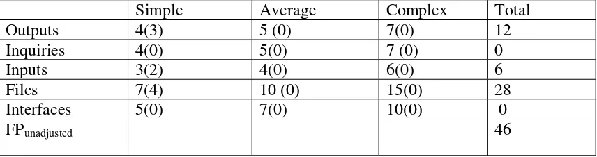
4.1.2 Weights for features
Simple Average Complex Total
Outputs 4(3) 5 (0) 7(0) 12
Inquiries 4(0) 5(0) 7 (0) 0
Inputs 3(2) 4(0) 6(0) 6
Files 7(4) 10 (0) 15(0) 28
Interfaces 5(0) 7(0) 10(0) 0
FPunadjusted 46
Table 1: Weights for features
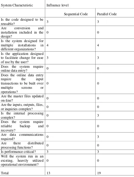
4.1.3 Influence Factors
System Characteristic Influence level
Sequential Code Parallel Code
Is the code designed to be
reusable? 3 3
Are conversion and installation included in the design?
0 0 Is the system designed for
multiple installations in different organizations?
4 4 Is the application designed
to facilitate change for ease of use by the user?
3 3 Does the system require
online data entry? 0 0
Does the online data entry require the input transactions to be built over multiple screens or operations?
0 0
Are the master files updated
on-line? 0 0
Are the inputs, outputs, files,
or inquiries complex? 0 0
processing functions? 0 0
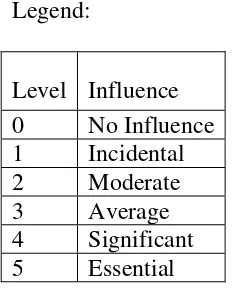
Legend:
Level Influence
0 No Influence
1 Incidental 2 Moderate 3 Average 4 Significant 5 Essential Table 3: Legend
Sequential Code:
Process Complexity Adjustments = .65 + 0.01 * (sum of influence ratings) = .78
FPadjusted = FPunadjusted * (.65 + 0.01 * (sum of ratings)) = 46 * (.65 + .01 * (13)) = 35.88 Source lines of code (SLOC) = FP * Language Factor (for Java) = 35.88 * 40 = 1435.2
Parallel Code:
Process Complexity Adjustments = .65 + 0.01 * (sum of influence ratings) = .84
FPadjusted = FPunadjusted * (.65 + 0.01 * (sum of ratings)) = 46 * (.65 + .01 * (19)) = 38.64
Source lines of code (SLOC) = FP * Language Factor (for Java) = 38.64 * 40 = 1545.6
4.2 Cost Estimation by COCOMO Model
The above table lists the equations to calculate the Person Months (a measure of programmer productivity) and the development time in months for a given KLOC/KDSI* for different types of Software Programs i.e. Application programs, Utility programs and System Programs. The current software project fits into the category of an application program.
5. Architecture Elaboration Plan
The following activities have to be accomplished prior to the architecture presentation:
• Action Items: The action items identified during each of the phases, along with
the efforts made to satisfy them, will be documented.
• Updated Vision Document: The vision document will be updated to provide a
complete and adequate representation of all the requirements. A set of “critical” requirements will be identified by ranking the requirements according to
importance. These modifications will be based on the recommendations made by the members of the graduate committee.
• Updated Project Plan: The project plan will detail the phases, iterations, and
milestones that will comprise the project. Each deliverable will be included in the plan with estimated dates, sign-offs and evaluation criteria.
o Cost Estimate: The document will also provide an updated estimate on the size, cost and effort required for the project implementation.
• Formal Requirement specification: The properties of the system are formally
expressed using Object Constraint Language (OCL). Use of a formal language to express the requirements will help making them adequate (it will adequately state the problem at hand), internally consistent (it will have a meaningful semantic interpretation that makes true all specified properties taken together),
unambiguous (it may not have multiple interpretations of interest making it true), and minimal (it should not state properties that are irrelevant to the problem or that are only relevant to a solution for that problem).
• Architecture Design: The complete architectural design of the project is
documented using modeling languages such as UML. Use case diagrams, Class diagrams and sequence diagrams will be used to illustrate the architecture design of the system. Re-use of pre-existing components will be documented.
• Test Plan: A set of test cases, the types of tests that will be used for these test
cases, the data that will be used for each test case and the requirement traces for each test case will be identified. The results of the test are documented.
• Formal Technical Inspection: One of the technical artifacts (design, formal
requirement or executable prototype) will be subjected to a formal technical inspection by two independent MSE students – Srinivas Kolluri and
• Executable Architecture Prototype: An executable architecture prototype will be
CHAPTER 4: SOFTWARE QUALITY ASSURANCE PLAN
1. Introduction
This document explains the Software Quality Assurance Plan (SQAP) for MSE project of Lakshmikanth Ganti. The project is to develop an application in Java that uses Molecular Dynamics Simulation techniques to simulate the interaction between the atoms in a group of molecules.
1.1 Purpose
Software Quality Assurance Plan (SQAP) consists of those procedures, techniques and tools used to ensure that a product meets the requirements specified in software requirements specification.
1.2 Scope
The scope of this document is to outline all procedures, techniques and tools to be used for quality assurance of this project.
This plan:
• Identifies the SQA responsibilities of the project developer and the SQA
consultant
• Lists the activities, processes, and work products that the SQA consultant will
review and audit
1.3 Reference Documents
• Lecture notes, CIS 748 Software Management, Dr. Scott Deloach, Spring 2002
• Lecture Notes, CIS 771 Software Specifications, Dr. John Hatcliff, Spring 2001
• Software Engineering, Roger S. Pressman, 5th Ed.
• IEEE Guide for Software Quality Assurance Planning, IEEE STD 730.1 – 1995.
• IEEE Standard for Software Quality Assurance Plans, IEE STD 730 – 1998.
1.4 Overview of the Document
The rest of the document is organized as follows:
Management: A description of each major element of the organization and a description of the SQA tasks and their relationships
Documentation: Identification of the documents related to development, verification, validation, use and maintenance of the software.
SQAP Requirements: This section defines the SQA review, reporting, and auditing procedures used to ensure that software deliverables are developed in accordance with this plan and the project’s requirements.
Training: This section describes the training program for the developer.
2. Management
2.1 Organization
member involved, it will be the sole responsibility of the developer to review the product’s usability, efficiency, reliability, and accuracy. The major professor will however conduct inspections, reviews, and walk-through on a regular basis. In addition a committee consisting of the major professor and two other faculty members will review the documents of each phase before every presentation. Major Professor's and the committee’s specifications and suggestions will be used in places where quality decisions need to out-weigh development schedule decisions.
2.2 Roles
• The committee consists of Dr. Virgil Wallentine, Dr. Paul Smith and Dr.Mitch
Neilsen.
• Major Professor: Dr. Virgil Wallentine
• Developer: Lakshmikanth Ganti.
2.3 Tasks and Responsibilities
The responsibilities of the developer are as follows:
• Develop the requirement specification and cost estimation for the project
• Develop the design plan and test plan for testing the tool
• Implement and test the application and deliver the application along with the
necessary documentation
• Give a formal presentation to the committee on completion of the analysis, design
• Planning, coordinating, testing and assessing all aspects of quality issues.
The responsibilities of the committee members are to:
• Review the work performed by the developer
• Provide feedback and advice
2.4 SQA Implementation in different phases
Quality assurance will be implemented through all the software life cycles of the tool’s development process, until the release of the software product. The following are the quality assurance tasks for each phase of the software development:
Requirements phase: When the SRS is being developed, the developer has to ensure that it elucidates the proposed functionality of the product and to keep refining the SRS until the requirements are clearly stated and understood.
Specification and Design phase: Due to the great importance for accuracy and
completeness in these documents, weekly reviews shall be conducted between the developer and the professor to identify any defects and rectify them.
Implementation phase: The developer shall do code reviews when the construction phase of the Tool begins.
Software testing phase: The developer shall test each case. The final product shall be verified with the functionality of the software as specified in the Software Requirements Specification (SRS) for the Tool.
Through all these phases of the software development, the following shall also be conducted to improve the software quality:
• Communication and Feedback: The developer is encouraged to freely express
disagreements, suggestions and opinions about all aspects of the weekly process of software development.
• Internal audits and evaluations: The Major professor and the committee are
expected to do auditions and evaluations at the end of each phase in the project.
3. Documentation
In addition to this document, the essential documentation will include: 1) The Software Requirements Specification (SRS), which
• Prescribes each of the essential requirements (functions, performances, design
constraints and attributes) of the software and external interfaces
• Objectively verifies achievement of each requirement by a prescribed method
(e.g. Inspection, analysis, demonstration or test)
• Facilitates traceability of requirements specification to product delivery.
• Gives estimates of the cost/effort for developing the product including a project
plan.
2) The Formal Specification Document, which gives the formal description of the product design specified in Object Constraint Language (OCL).
The Software Design Description (SDD)
• Describes the components and sub-components of the software design,
including various packages and frameworks, if any.
• Gives an object model that is developed using Rational Rose highlighting the
essential classes that would make up the product.
• Gives a sample interaction diagram, showing the key interactions in the
application. This should also be a part of the object model.
3) Software Test Plan: Describes the test cases that will be employed to test the product.
4) Software User Manual (SUM)
• Identify the required data and control inputs, input sequences, options, program
limitations or other actions.
• Identify all error messages and describe the associated corrective actions.
• Describe a method for reporting user-identified errors.
• Documented Source Code.
The following documents will be provided at the end of each phase by the developer: Phase 1: Objectives
• Project Overview
• Cost analysis
• Project plan
• Software quality assurance plan
Phase 2: Architecture
• Implementation Plan
• Formal Requirement Specification
• Architecture design
• Test plan
Phase 3: Implementation
• User Manual
• Assessment Evaluation
• Project Evaluation
• References
• Formal Technical Inspection Letters
Appendix
• Source code
4. SQA Program Requirements
4.1 Standards
• Coding standards – Java 1.4
• Coding Documents standards – Java Documentation
• Test Standards – IEEE Standard for software test documentation
4.1.Metrics
• LOC - lines of code is used to measure the size of the software
4.2.Software Documentation Audit
Quality Assurance for this project will include at least one review of all current work products in each stage of development (Requirement, Design, and Implementation). The reviews will assure that the established project processes and procedures are being followed effectively, and exposures and risks to the current project plan are identified and addressed. The review process includes:
• A formal presentation at the end of each development phase (Requirement,
Design and Implementation). All current work products are presented to the committee members for review.
• A managerial review by the advisor periodically to ensure the work generated is
in compliance with project requirements.
• Reviews by the committee after each presentation.
4.3.Requirements Traceability
4.4.Software Development Process
The software development process involves three stages: 1) Requirements phase, 2) Design phase (this phase also involves the development of the product prototype and 3) Implementation and testing phase. During each phase, the Major Professor and the committee will review the deliverable documents. The developer would incorporate modifications suggested by the committee. This would ensure quality of the software product.
4.5.Project Reviews
The Committee will perform a review at the 3 stages of the project as described in the section above. This review will determine whether the requirements have been met for the deliverable, check that the product meets the requirements, ensure that the SQA plan has been adhered to, verify the performance of the software and ensure that acceptance testing is carried out. In addition the developer will conduct a Formal Technical Review after the design phase. A design checklist will be used and the developer will check to see whether his/her design meets the checklist criteria.
4.6.Testing and Quality Check
5. Training
The following courses taken by the developer at Kansas State University and Research experience under the guidance of Dr. Virgil Wallentine and Dr. Paul Smith will provide the required training.
• CIS 540: Software Engineering –1
• CIS 740: Software Engineering – 2
• CIS 748: Software Management
• CIS 771: Software Specification
CHAPTER 5: ARCHITECTURE DESIGN
1. Introduction
The purpose of this document is to describe the architecture design of the Molecular Dynamics Simulation tool that will capture the requirements as outlined in the requirements specification section. The document will outline the goals, key design principles along with class diagram and sequence diagrams.
2. References
IEEE STD 1016-1998, “IEEE Recommended practice for Software Design Description”.
3. Definitions and Abbreviations
• SDD: Software Design Description
• Molecular Dynamics Simulation: A technique where the time evolution of a set of
atoms is followed by integrating their equations of motion.
• Lennard-jones potential: An interaction potential existing between atoms that are
considered here.
• PDB: Protein Data Bank
• Potential Energy: The energy resulting from position or configuration of an atom.
• Kinetic Energy: The energy resulting from motion of an atom.
• Cut-off distance: Distance between atoms above which there are no interaction
forces.
4. Goals
The overall goal of the system is to calculate the final coordinates of all the atoms, the energies and the temperature of the system after simulating through a certain number of time steps. This depends on doing the following tasks correctly at each time step: 1) Calculate the force on an atom due to every other atom within the interaction distance 2) Use the force calculated above to calculate the increment in velocity and displacement of the atom.3) Calculate the potential energy contributed by each atom in the system.4) Calculate the total Kinetic energy of the system and the temperature of the system using the kinetic energy.
5. Key Design Principles
5.1 Algorithm
1. Compute forces.
Clear potential and force accumulators
V := 0
for i = 1 to Np do Fi: = 0 Accumulate forces for i = 1 to Np – 1 do for j = i + 1 to Np do
Find force Fij of particle j on particle i Fi: = Fi + Fij
Fj: = Fj - Fij
Find the potential energy contribution V = V + Vij
2. Integrate equations of motion for i = 1 to Np do
Velinew: = Veliold + (Fi/mi)DT Xinew: = Xiold + VeliDT 3. Update time counter
t: = t + DT
The equations for calculating Fij and Vij are called the Lennard-Jones equations for calculating potential and force and are given as follows:
and are the specific Lennard--Jones parameters, different for different
interacting atoms. r is the distance between the interacting atoms. The values of these parameters for the system under consideration are: σ = 0.3 nanometers and ε = 1.0 KJ/mole. The Lennard--Jones force between two atoms is given by the equation:
5.2 Design
Performance is a key issue in computationally intensive systems such as the one being programmed here. The majority of the computation in the code occurs in the calculation of force on each atom due to every other atom. The fact that there will be no interacting forces between atoms whose separation is greater than a specific cut-off distance is taken into consideration and the following model is designed for calculating forces, which improves performance.
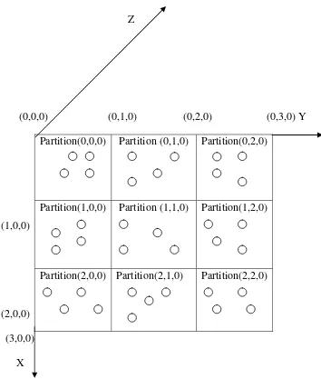
The ideal number of partitions in the current system would be 8x8x8, since the length of the simulation box is 8.09202 nm and the cut-off distance is 1.0 nm, and the length of each partition would be 1.0115025 nm. Each partition is uniquely identified by three indices. For example if each partition is of length 1, then the partition which is identified by partition (0,0,0) holds the atoms whose coordinates are such that 0<=x<1, 0<=y and 0<=z<1. The following diagram shows how the whole system of atoms is assigned to partitions. The partitions are connected like a torus interconnection system to accommodate the periodic boundary conditions property of the simulation system. So, partition (0,2,0) is the left neighbor of partition (0,0,0). Similarly partition (2,0,0) is the
Z
(0,0,0) (0,1,0) (0,2,0) (0,3,0) Y Partition(0,0,0) Partition (0,1,0) Partition(0,2,0)
Partition(1,0,0) Partition (1,1,0) Partition(1,2,0)
(1,0,0)
(2,0,0)
Partition(2,0,0) Partition(2,1,0) Partition(2,2,0)
(3,0,0) X
Figure 4: Partitions of the system
Initialize forces and potential energy
check if distance between the atoms < cut-off distance
{
exploited here by examining each pair of bodies just once (note the check “check if atom number in partition1 > atom number in partition2”).
5.3 Design considerations for a parallel program
The current project is an ideal application of parallel programming owing to the intense computational nature of the molecular dynamics simulations. Parallelizing the program and running it on multiple processors significantly reduces the time taken for the simulation, since the work is shared by multiple threads each running on different processors.
The simplest design of a parallel program from the above sequential code would be to distribute the partitions equally between all the threads. At the end of iteration, each thread has to communicate with its neighboring threads by passing all its bordering partitions which will be required by its neighboring threads to run the simulation of its own partitions. Various designs for a parallel program based on 1) Synchronization mechanism, 2) the pattern of thread creation and 3) Granularity, are explained below:
5.3.1 Design based on Synchronization Mechanism
synchronization can be achieved are by 1) message passing between threads and 2) using a barrier to stop all the threads, at the point where synchronization is required.
a) Message Passing
The message passing between the threads is carried out using Bounded Buffers. Each bounded buffer is represented by an object of the Java class “Objbuf” which is described in detail later in the class diagram section of this document. Two unique bounded buffers exist between each pair of neighboring threads: one to put the objects to be transferred and one to get them. The threads with which a thread communicates directly are referred to as neighboring threads. The number of neighboring threads and the mechanism of message passing depend on the pattern of thread creation, which is explained in detail in the next section. Message passing is used only when the neighboring threads need to synchronize with each other.
b) Barrier Synchronization
5.3.2 Design based on pattern on thread creation
The pattern in which the threads are arranged has no effect on the barrier synchronization mechanism since when a barrier is used we intend that all the threads be stopped irrespective of how they are arranged. However, it affects the message passing mechanism since the number of neighbors for a thread and who they are is changed based on the pattern in which they are arranged. Two possible patterns are 1) 3-D grid shaped – where each thread communicates with its twenty six neighbors and 2) Vertical pipeline – where every thread communicates only with its upper and lower neighbors. The system requires that the connections are based on torus inter-connection system i.e. in the case of Vertical pipeline, the lower neighbor of the bottom most thread is the top most thread and vice versa. The following sub-sections describe the creation of threads and message passing between them for each pattern:
a) 3-D Grid shaped
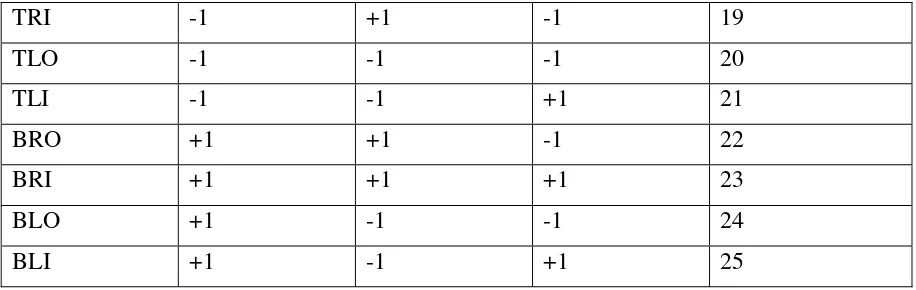
identifiers. The fourth dimension determines the other thread, which it is associated to i.e. top or left etc. The following mapping helps to determine the neighboring thread’s coordinates with relative to the coordinates of the current thread and the value of the fourth dimension of the corresponding bounded buffer. The naming convention is T: Top, B: Bottom, L: Left, R: Right, O: Outer, I: Inner. So the neighboring threads are these and their combinations. E.g. TRO represents the Top-Right-Outer thread.
Neighboring thread.
TRI -1 +1 -1 19 Table 5 : Bounded Buffer Coordinates in 3D Grid System
Each thread has an array of buffers of size 26 called “buf []” to get the bordering partitions of the neighboring threads and an array of buffers called “shad []” to put its bordering partitions into them so that the corresponding thread will fetch them. These buffers and shadows should be properly defined so that the buffer of a thread is the same as the shadow of one of the neighboring threads. For e.g. the top shadow of a thread should be the bottom buffer of the thread’s top neighbor. It is also important that the correct partitions are transferred to the corresponding neighbors. For e.g. the top layer of the partitions array is to be transferred to the top neighbor.
b) Vertical Pipeline
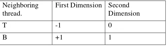
[M][2]. The first dimension is the same as the thread identifier and the second dimension determines the other thread, which it is associated to i.e. top or bottom. The following mapping helps to determine the neighboring thread’s coordinate relative to the coordinate of the current thread and the value of the second dimension of the corresponding bounded buffer. The naming convention is T: Top, B: Bottom.
Neighboring Table 6: Bounded Buffer Coordinates in Vertical Pipeline system
Each thread has an array of buffers of size 2 called “buf []” to get the bordering partitions of the neighboring threads and an array of buffers called “shad []” to put its bordering partitions into them so that the corresponding thread will fetch them. These buffers and shadows should be properly defined so that the buffer of a thread is the same as the shadow of one of the neighboring threads. For e.g. the top shadow of a thread should be the bottom buffer of the thread’s top neighbor. It is also important that the correct layer of partitions is transferred to the corresponding neighbors. For e.g. the top layer of the partitions array is to be transferred to the top neighbor.
5.3.3 Design based on Granularity
increased or decreased by altering the number of partitions assigned to a thread. For a system of fixed size, the more the number of threads, the less the granularity is. Granularity can also be increased by increasing the system size with a fixed number of threads. Measurements of the speed up with different levels of granularity will be performed.
The pseudo code for the run method of a thread i.e. what each thread will do in parallel is as follows:
For time step = 1 to number of iterations {
1) assign the atoms to the partitions that belong to this thread depending on their spatial configuration
2) put the bordering partitions in the corresponding shadows.
3) collect the bordering partitions of the neighbors from all the buffers. 4) calculate forces.
5) increment velocities and calculate displacements.
6) Calculate energies due to the contribution of atoms in this thread’s partitions and send them to energy writer class.
}
6. Class Diagram
Figure 5: Class Diagram
6.1 Class Atom
An object of this class represents each atom in the simulation system. It has the forces, velocities, and coordinates in all directions as its attributes and has get and set methods for each of these attributes.
6.2 Class IO_Utils
This is a helper class, which has methods for formatting an integer or a double to be outputted to a file in a specified pattern.
6.3 Class LineReader
This is a helper class which has methods that browse through a file and reads it line by line for a string, double or integer input.
6.4 Class ObjBuf
this variable in each of the methods. So, a thread waits in the get() method if the buffer is empty and likewise waits in the put() method if the buffer is full.
6.5 Class EnergyWriter
Since the energy calculations are distributed over multiple threads and non-neighboring threads could be at different time steps at a time, we need a class that collects the energy contributions from each thread at a particular time step and adds them together to get the totals. This is the class that does this work. It has methods for a) collecting the potential and kinetic energies form the threads at each time step b) calculating the averages and fluctuations for each of the physical quantities at each time step i.e. potential energy, kinetic energy, total energy and temperature c) printing the energies and temperature at every specified number of time steps to a file in a specified format.
6.6 Class ParThread
This is a Java Thread class and has methods to do the following tasks which are called in the standard run() method.
• Assign atoms to the partitions belonging to itself based on the atom’s coordinates
• Put the bordering partitions of this thread in all of the neighboring shadows
• Calculate forces on the atoms of the partitions belonging to this thread due to
every other atom with in the interaction distance.
• Increment the velocities and displace the atoms of the partitions belonging to this
thread.
• Pass the kinetic energy and potential energy contribution due to the atoms of the
partitions belonging to this thread, to the EnergyWriter class at each time step.
6.7 Class MdPar
This is the main class, which is responsible for starting the simulation. It creates an array of threads, joins them and records the time taken for the entire simulation. This class is also responsible for 1) initializing the coordinates and velocities of the Atoms with the data read from the velocity and coordinate input files, 2) initializing the values of the physical constants required in the simulation with the data read from the md.dat input file and 3) write the final positions of the Atoms after simulation to the coordinates output file.
6.8 Class MdConstants
6.9 Class Barrier
This class is used for synchronizing all the threads at a given point. A common Barrier is shared between all the threads. Whenever all the threads need to stop at a point and synchronize, each of the threads calls the gate () method in this class. This is used only when all the threads in the system need to stop and synchronize. If we need only the neighboring threads to stop and synchronize, the ObjBuf class serves the purpose in addition to communicating objects between the threads. In our system it is observed that the atoms did not move more than twice the length of the partition during a simulation with 100 iterations. That means a thread needs to wait only for the neighboring threads and synchronize. So an ObjBuf could be used instead of a Barrier. The Barrier class provides synchronization through the use of the Semaphore Classes (Binary and Counting Semaphores).
7. Use Cases
The primary use cases in the system are listed below and explained with the help of sequence diagrams.
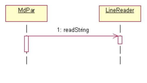
7.1 Read Data from input files
desired data e.g. velocities or coordinates in double format and other data values in integer format.
Figure 6: Sequence Diagram, Read Data From Input Files
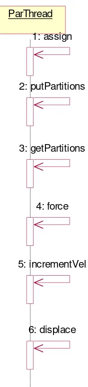
7.2 The sequence diagram below illustrates the following use cases, which involve method calls in the same class itself.
• Assigning atoms to a partitions of a thread depending on their spatial coordinates
• Put bordering partitions in all the thread’s shadows for its neighboring threads to
collect.
• Get bordering partitions from all the neighboring threads.
• Calculate forces on atoms in the partitions of the current thread
ParThread ParThread
1: assign
2: putPartitions
3: getPartitions
4: force
5: incrementVel
6: displace
Figure 7: Sequence Diagram
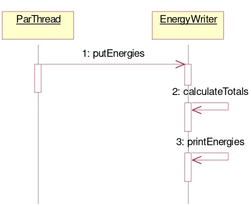
7.3 Calculate and print energies
method which calculates the total energy contributed by all the threads and calls the printEnergies() method which prints the energies to the console and a file at every given number of steps.
ParThread
ParThread EnergyWriterEnergyWriter
1: putEnergies
2: calculateTotals
3: printEnergies
Figure 8: Sequence Diagram, Calculate and Print Energies
7.4 Calculate averages and fluctuations of energies and temperature and write them to a file.
The main class (MdPar) calls the calculateAvgsAndFlucs() method of the EnergyWriter class, which calculates the averages and fluctuations of the potential energy, kinetic energy and the temperature and calls the printEnergies() method to output them to the console and a file.
MdPar
MdPar EnergyWriterEnergyWriter
1: calculateAvgsAndFlucs
2: printEnergies
CHAPTER 6: FORMAL REQUIREMENTS SPECIFICATION
1. Introduction
The purpose of this document is to present the process of formal specification and verification of the synchronization technique used in this project. Java Path Finder (JPF) has been used to formally specify and verify the synchronization properties of the system.
2. Java Path Finder
The Java Path Finder [8] is a translator from a subset of Java 1.0 to PROMELA, the programming language of the SPIN model checker. This tool is designed to establish a framework for verification and debugging of Java programs based on model checking. It simplifies the verification of Java programs by obviating the need to manually reformatting the program into a different notation (e.g. PROMELA or OCL), in order to analyze the program. This system is especially suited for analyzing multi-threaded Java applications, of which the current project is an example. The system can find deadlocks and violations of Boolean assertions stated by the programmer in a special assertion language.
3. Model
six neighbors and a buffer associated with it. The model with communication between all the twenty six threads has an enormously huge state space and very intensive in terms of time and resources. So the following prototype is proposed for the communication and has been specified using JPF:
Figure 10: JPF Model
4. JPF Specification
5. JPF Result
The above model is verified by JPF for its safety properties and assertion violations in all the possible states that can be reached. The following is the result by JPF:
=================================== No Errors Found
===================================
--- States visited : 8,970,992 Transitions executed : 27,423,628 Instructions executed: 864,227,005 Maximum stack depth : 720 Intermediate steps : 1,181,428 Memory used : 1.1GB Memory used after gc : 1.05GB Storage memory : 59.43MB Collected objects : 27,051,899 Mark and sweep runs : 25,795,428 Execution time : 3:06:53.591s Speed : 2,445tr/s
CHAPTER 7: TEST PLAN
1. Test Plan Identifier
MSE – TP 01
2. Introduction
The purpose of this document is to outline the plan for testing all the critical use cases and functionality of the Molecular Dynamics Simulation tool. The document will also describe the tools and environment used to test the software.
3. References
The following documents are used for reference:
• Software Requirements Specification
• Architecture Design
4. Test Items
The following features are to be tested:
• Read Data from files
• Read Program Arguments
5. Features not to be tested
The communication between the threads is not to be tested again, since we already validated the code for communication using Java Path Finder and ensured that it is free from deadlocks and uncaught exceptions.
6. Approach
The specific requirements specification is used as a guide to test the above-mentioned features of the software.
6.1 Read Data from files.
The software should read data from the files in a specific format i.e. integer, string or a double. Exceptions should be raised appropriately whenever a wrong format or a blank line is encountered.
6.2 Read Program Arguments:
The program should catch exceptions in the program arguments and throw an appropriate error message. For e.g., the program has an argument, the number of threads, which can be only 1,2,4 or 8.
6.3 Formatting values for output
6.4 Functional Testing
The program is tested for correctness i.e. it should give the same results when run on any number of threads.
6.5 Performance Requirements Testing
All performance requirements will be tested against their requirements described in the software requirements specification document.
7. Item/Pass Fail Criteria
The software should be able to pass all the tests for all the features and performance requirements as described in the Software requirements Specification document. Each feature will be considered passed if it satisfies the corresponding requirement and failed if the expected behavior is not met or if any exceptions are raised.
8. Suspension Criteria and Resumption Requirements
8.1 Suspension Criteria
8.2 Resumption Requirements
Testing will be resumed when all the functions listed above work adequately and correctly. When testing for new releases, testing will resume when all the features of the previous release are considered passed.
9. Test Deliverables
The following artifacts are produced after tests are conducted on the simulation software.
• Test Plan
• Test cases and results
10. Environment
CHAPTER 8: COMPONENT DESIGN
1. Introduction:
The purpose of this document is to outline the design of all the components (classes) of the software and the interaction between them necessary to achieve the desired results. The objective of the project is to develop a parallel program for the Molecular Dynamics simulation of a group of atoms acted upon by an interaction force called the Lennard-Jones force of interaction. The following sections explain in detail all the classes and their functions .The Object Model is used as a reference to explain the functionality of each class.
set_forces(x : double, y : double, z : double) set_velocities(x : double, y : double, z : double) set_positions(x : double, y : double, z : double)
An instance of this class represents an atom in the system. It holds the values of the forces, velocities and coordinates in all the directions. The methods of this Atom class are used to set or get the velocities, forces or coordinates of an atom at any instant of time. The detailed description of the methods of this class is as follows:
set_positions
public void set_positions(double x, double y, double z)
Sets the coordinates in x, y and z directions Parameters:
Sets the velocities in x, y and z directions Parameters:
Gets the coordinates in x, y and z directions Returns:
get_velocities
public double[] get_velocities()
Gets the velocities in x, y and z directions Returns:
velocities - the x, y and z velocities packed in an array
get_forces
public double[] get_forces()
Gets the forces in x, y and z directions Returns:
forces - the x, y and z forces packed in an array
3. class Barrier
Figure 12: Class Barrier
This class is mainly used for synchronization purposes. A common barrier is shared between all the threads. This is used only when it is required that all the threads stop. If not, the ObjBuf class is used for synchronization between the neighboring threads.
join
public void join()
Joins the Barrier thread
gate
This is the method that is started when the current thread is instantiated Specified by:
This class extends the Semaphore Class and is an implementation of the Binary
Semaphore i.e. this semaphore can have only two values.
5. class CountingSemaphore
CountingSemaphore
CountingSemaphore()
CountingSemaphore(initial : int)
This class extends the Semaphore Class and is an implementation of the Counting Semaphore which can have any number of values.
6. class EnergyWriter
Figure 15: Class EnergyWriter
This class is responsible for collecting the individual contributions of energies from all threads at each iteration step, calculate the total energies, averages, fluctuations and temperatures, and display them to the console as well as write to a file after every given number of steps. The detailed description of the methods of this class is as follows:
putEnergies
public void putEnergies(double pot_energy, double kin_energy, int id,
int num_iter)
throws java.lang.Exception
Collects the energy contributions from the individual threads Parameters:
pot_energy - - potential energy contribution of a thread kin_energy - - kinetic energy contribution of a thread id - - thread index
num_iter - - the current iteration step of the thread Throws:
putAtomCount
public void putAtomCount(int count, int id,
int num_iter)
This method is for only debugging purposes, to make sure that an atom is assigned only to one thread in each iteration
Parameters:
count - - Number of atoms that the thread holds id - - thread index
num_iter - - the current iteration step of the thread
calculateTotals
public void calculateTotals(int num_iter)
throws java.lang.Exception
Sum the individual contributions of each thread and calculate the total energy and temperature of the system
Parameters:
num_iter - - the iteration at which these energies and temperature are calculated Throws:
java.lang.Exception
calculateAvgsAndFlucs
public void calculateAvgsAndFlucs()
throws java.lang.Exception
Calculate Averages and Fluctuations of Energies and Temperatures over the length of the simulation
Throws:
Write energies and temperature to a file Parameters:
num_iterations - - the iteration step at which these are written total_energy - - total energy of the system
pot_energy - - potential energy of the system kin_energy - - kinetic energy of the system temperature - - temperature of the system Throws:
7. class IO_Utils
IO_Utils
doubleFormat(s : String, d : double, column_spaces : int) : String intFormat(n : int, num_alloc : int) : String
Figure 16: Class IO_Utils
IO_Utils is a helper class which has the methods for formatting numbers in a specific decimal format. This is useful while printing out energies and the final coordinates. The detailed description of the methods of this class is as follows:
doubleFormat
public static java.lang.String doubleFormat(java.lang.String s, double d,
int column_spaces) formats a double number in the required format
Parameters:
s - - the string pattern representing the format e.g. "###.##" d - - the double that needs to be formatted
column_spaces - - the number of spaces to be allocated for writing to file or console
Returns:
to_return - the formatted number as a string
intFormat
public static java.lang.String intFormat(int n,
int num_alloc) formats an integer to be outputted in a specified pattern Parameters:
n - - the integer to be outputted
num_alloc - - the number of spaces to be allocated while writing to file or console Returns:
8. class LineReader
LineReader is a Helper Class which reads a line of input from the given input stream. This is used to read the positions, velocities and values of the constants used for computation, from input files. The detailed description of the methods of this class is as follows: reads an integer input
Parameters:
prompt - - the prompt used to ask for input Returns:
input - the integer entered
readDouble
public double readDouble(java.lang.String prompt) reads a double input
prompt - - the prompt used to ask for input Returns:
input - the double entered
9. class MdConstants
MdConstants ntot : int eps : double sigma : double wmass : double box_length : double nstep : int
dt : double tbath : double ig : long rcut : double ntpr : int hdt : double hdt2 : double ckb : double M : int
Figure 18: Class MdConstants
10. class MdPar
Figure 19: Class MdPar
main
public static void main(java.lang.String[] args)
readData
private static void readData()
Read Values from md.dat values and assign them to the values in the Constant class
readCoordinates
private static void readCoordinates()
Read the coordinates from the positions file and assign to the atoms
readVelocities
private static void readVelocities()
Reads the velocities from the file vel.in, this method is called only for testing purposes
calculateVelocities
private static void calculateVelocities()
Calculates and sets the velocities of the atoms based on a random Gaussian distribution
gauss
private static double gauss(double am, double sd)
assigns velocities to the atoms randomly based on the Gaussian distribution Parameters:
am - - the mean of the distribution sd - - the random number seed Returns:
r - the velocity assigned
writeFinalCoords
private static void writeFinalCoords()
11. class ObjBuf
Figure 20: Class ObjBuf
This class represents a buffer in which a thread can put an array of partitions or get an array of partitions from it. The put and get methods are synchronized, thus enabling synchronized communication between the threads. Each pair of neighboring threads shares two instances of this class, one for putting the partitions and another for getting the partitions. The put buffer for a thread will be the get buffer for its neighbor and vice-versa. This class is used while transferring the partitions of a thread to all its neighboring threads at each iteration step. The detailed description of the methods of this class is as follows:
put
public void put(java.lang.Object x) Put an array of Partitions
Parameters: x - - An Object
get
public java.lang.Object get() Get an array of Partitions Returns: