Application of Buckling Restrained Braces for Seismic
Strengthening of Irregular Gravity Load Designed Reinforced
Concrete Frame Buildings
Chandra, J.1 and Warnitchai, P.2
Abstract: Past earthquake disasters have shown that irregular gravity load designed (GLD) reinforced concrete (RC) frame buildings were very vulnerable to strong ground shaking. Many of them collapsed and caused loss of human lives as well as materials. Hence, in order to prevent future disasters, this type of buildings needs to be strengthened against earthquake. This paper presents a case study of an innovative approach for seismic strengthening of a typical six story residential building with a soft/weak first story using buckling restrained braces (BRBs). The seismic performance of the original GLD building and the retrofitted one are compared using three dimensional nonlinear dynamic time history analysis in OpenSees. The analysis results show that the innovative seismic strengthening approach for irregular GLD RC frame buildings using BRBs can significantly reduce maximum story drifts as well as building damages which
benefits in reducing the risk of building’s collapse during earthquake.
Keywords: Irregular GLD RC frame buildings, seismic strengthening, buckling restrained braces.
_
Introduction
Due to lack of expertise in seismic design concept and construction practices, many reinforced concrete (RC) frames are only designed for gravity loads and thus are called gravity load designed (GLD) buildings. The seismic performance of GLD buildings is very poor due to non-ductile reinforcement detailing and inappropriate proportioning of beams and columns which results in strong beam-weak column behavior. Furthermore, GLD buildings are not designed based on modern seismic building codes. Therefore, most of them have irregularities such as soft story, setback, and unsymmetrical plan which make it difficult to predict the behavior of the buildings when subjected to earthquake. Most of the time, these irregularities are indeed making the
1 Civil Engineering Department, Petra Christian University,
Sura-baya, INDONESIA.
Email: [email protected]
2 School of Engineering and Technology, Asian Institute of
Technology, Bangkok, THAILAND.
Note: Discussion is expected before November, 1st 2011, and will be
published in the “Civil Engineering Dimension” volume 14, number 1, March 2012.
Received 18 May 2010; revised 19 August 2011; accepted 24 August 2011.
Many seismic strengthening techniques have been developed to improve the seismic performance of GLD buildings, such as jacketing (either with concrete, steel or fiber reinforced polymer), adding concrete or masonry walls, and adding steel braces. It should be noted that there is no single solution or one best method that can satisfy all design considerations in any condition. Hence, researches in this area are still going on to find other alternatives which can produce better solution in the future.
One of the most important developments in earthquake engineering in recent years is the
introduction of designing “damage controlled struc -tures” [1]. The basic idea of this concept is a global structure mainly consists of a primary structure and an auxiliary structure in which the primary structure will remain elastic even under strong earthquake while the auxiliary structure will take all of seismic forces. Damages will only occur in the auxiliary structure in which the damaged elements can be replaced after the earthquake and the structure remains operative even under strong earthquake. This “damage control” concept can be applied not only for designing new structures, but also for strengthening existing structures. Further-more, this concept fits well with the condition of GLD buildings in which the primary structures are not designed to resist earthquake loading. One recent seismic strengthening technique for GLD buildings
that adopts this “damage control” concept is using
buckling restrained braces (BRBs).
performance, effective cost, fast construction time, minimal disruption to the building occupants, and aesthetics [2]. Study about the use of BRBs as a seismic strengthening technique for GLD buildings has been conducted by Mazzolani et al. [3]. The results show that BRBs provide adequate improvement in structural strength, stiffness, and ductility as compared to other techniques. Another study about the application of BRBs in streng-thening a non-ductile RC column has been conducted by Yooprasertchai [4]. The non-ductile RC column was designed to represent the characteristics of column in GLD buildings. The results show that BRBs can significantly improve the seismic performance of the GLD RC column. Indeed, these superiorities make BRBs become one of the most favorable methods nowadays to be used as a seismic strengthening technique for GLD buildings. Nevertheless, study about the application of BRBs for strengthening GLD buildings which also have irregularities such as soft story and unsymmetrical plan due to effect of infill walls has not been well considered. This is quite important since in many cases GLD buildings also have these types of
irregularities which make them more vulnerable to seismic hazard.
This study aims to investigate the application and effectiveness of BRBs to be used as a seismic strengthening technique for irregular GLD buil-dings. The effectiveness of BRBs is investigated in terms of enhancing the seismic performance of GLD buildings. Other factors such as cost, time, and aesthetics are not considered in this study.
Building Considered
A typical six story residential building with a soft/weak first story taken from field survey data in Bangladesh is chosen to be investigated. From statistical analysis, soft/weak first story is the most common type of irregularity found in GLD buildings in Bangladesh. Moreover, Bangladesh is one of developing countries in Asia which is located in seismic prone area. Many significant damaging earthquakes have occurred in Bangladesh and there are potentials for damaging earthquakes to take place in the future.
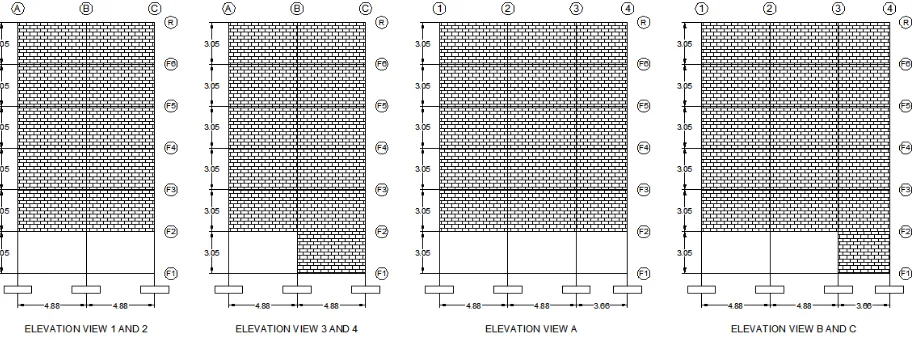
Figure 1. First floor plan (left) and typical floor plan (right) of the GLD building investigated
The investigated building has two identical spans with 4.88 m length in X-direction whereas in Y-direction it has two long spans with 4.88 m length and one short span with 3.66 m length. The story height is same for all floors which is 3.05 m. Furthermore, the GLD building investigated has soft story in the first floor due to absence of masonry infill walls. In the first floor, the infill walls are only in the corner part of the building plan while in other floors the infill walls are distributed well in the building plan. This arrangement of infill walls in the first floor is probably due to the function of the first floor as a car park area. The details of building plan and elevation views can be seen in Figures 1 and 2. The beam and column section details as well as the reinforcement arrangement can be seen in Figure 3. The column section has twelve deformed bars with 16 mm diameter for the longitudinal reinforcement and three legs tie of deformed bars with 10 mm diameter and 152 mm spacing. The beam section has four deformed bars with 16 mm diameter at the top and three deformed bars with same diameter at the bottom for the longitudinal reinforcement and two legs tie of deformed bars with 10 mm diameter and 152 mm spacing. Material properties, slab and wall thickness, and gravity loading are summarized in Table 1.
Figure 3. Details of column and beam sections (all dimen-sions are in millimeter)
Table 1. Summary of building’s data.
Concrete strength 17 MPa
Rebar strength 454 MPa
Masonry prisms strength 9 MPa
Slab thickness 152 mm (6 inch)
Infill wall thickness 127 mm (5 inch) Superimposed dead load 75 kg/m2 Design live load 200 kg/m2 Effective live load 20 kg/m2
Modeling of RC Structure
Computer models play important roles in numerical experiments. The use of inappropriate computer models may result in incorrect prediction of the complex behavior of GLD buildings. Therefore, computer models must be carefully determined and they should be able to simulate the complex behavior of GLD buildings including brittle failures. The computer models used in this study are explained in following sections.
Modeling of RC Beam, Column, and Beam-Column Joint
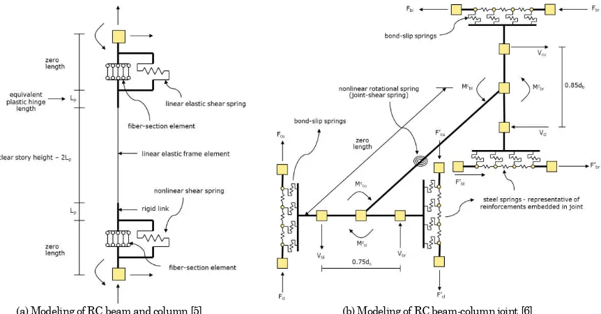
The RC beam, column, and beam-column joint models are taken from computer models developed by Suthasit and Warnitchai [5,6] which are able to simulate complex behavior of GLD buildings including brittle failures. The architecture of the models can be seen in Figure 4. Moreover, these models have been verified by Chandra [7] and Rayamajhi [8] with some real experimental results and the verification results show that these models can simulate quite well many possible failure mechanisms including the brittle ones.
(a) Modeling of RC beam and column [5] (b) Modeling of RC beam-column joint [6]
Modeling of RC Slab
In this study, since the investigated building has typical cast in place RC slab, it is therefore assumed that the RC slab behaves like a rigid floor diaphragm. This assumption is made in order to reduce the numbers of degree of freedom in the analysis which will reduce the computational effort. Furthermore, contribution of bending rigidity of the slab and the slab nonlinearity are also neglected in this study.
Modeling of Masonry Infill Wall
It has been well known that the effect of masonry infill walls should not be neglected in the seismic performance evaluation of RC buildings, especially GLD buildings. Therefore, in this study, a general approach for modeling of masonry infill wall recommended by FEMA 356 [9] is adopted. In this approach, the infill wall is modeled as a single equivalent diagonal compression strut which is connected concentrically to the RC frame.
Modeling of Foundation
In this study, the foundations are assumed to have fixed supports because of limited data about soil conditions, characteristics, and profile and limited data about foundations type, dimensions, and details.
Modeling of Buckling Restrained Brace (BRB)
As a special class of concentric brace element, the modeling concept of BRB is thus almost the same as conventional brace element. The only difference is that BRB does not buckle in compression, and hence it yields in tension as well as compression and has almost symmetrical hysteretic behavior whereas in case of conventional brace, the brace buckles in compression, and thus reduce the capability of the brace to dissipate energy during earthquake excitation. In this study, the BRB is modeled as a truss element with pin connection at both ends. The model has been verified by Chandra [7] and the verification results show that the model can simulate
very well the cyclic behavior of BRB.
Analysis Method
In this study, the software platform used is OpenSees [10]. OpenSees has been used widely nowadays to perform numerical simulation in the field of earthquake engineering. It serves as a powerful tool for numerical simulation of nonlinear systems.
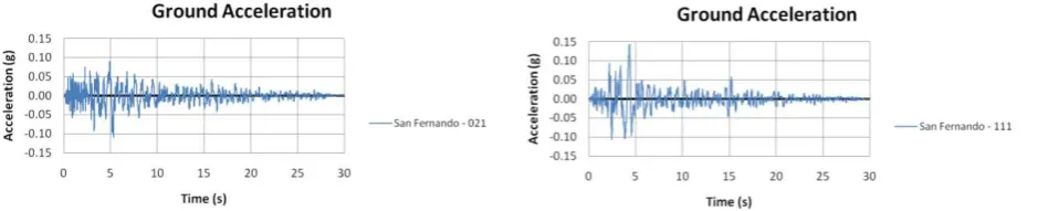
To investigate the effectiveness of BRBs to be used as a seismic strengthening technique for GLD building with a soft/weak first story, it is necessary to compare the seismic performance of the original GLD building and the retrofitted one. The seismic performance evaluation of both buildings is performed by three-dimensional nonlinear dynamic time history analysis. This advanced technique is used to take into account higher mode effects as well as the effect of unsymmetrical plan which will affect the analysis results. Two sets of ground motions taken from Pacific Earthquake Engineering Research Center (PEER) Strong Motion Database Next Generation Attenuation (NGA) Project [11] are used in this study. They are San Fernando (SF, 1971) earthquake and Northridge (NR, 1994) earthquake.
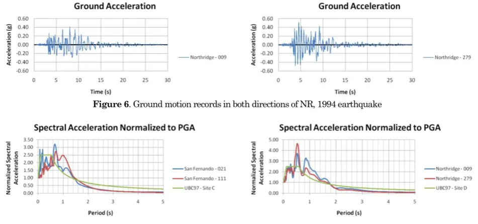
The original of these ground motion records as well as the spectral accelerations with 5% damping in both directions (X and Y) can be seen in Figures 5 to 7. Note that these spectral accelerations are compared with UBC 1997 spectra [12] in the respective site class. Later on, these ground motions are scaled based on 5% damped spectral
accele-rations at original GLD building’s fundamental
periods, T1 to simulate moderate and strong earthquakes [13]. The target spectral accelerations are set to 0.50g and 0.75g for moderate and strong earthquakes, respectively. Furthermore, the original
GLD building’s fundamental periods, T1, are 0.71s and 0.63s in X and Y directions, respectively. Since there are two horizontal components, thus spectral accelerations in both directions of these ground
motions at building’s fundamental periods, T1, are combined by geometric mean [14]. Then, scale factor
for these ground motions is determined as ratio of target spectral acceleration divided by combined spectral accelerations by geometric mean. The summary of scale factors used and the respective peak ground acceleration (PGA) of each ground motion in both directions are presented in Table 2.
Seismic Strengthening Scheme
The performance objectives of the seismic streng-thening scheme are to improve the seismic performance of the GLD building by preventing soft
story mechanism, to reduce building’s global dis -placements, interstory drifts, and building’s dama -ges. The seismic performance of the GLD building is poor due to soft story that exists in the first floor. This attracts deformation demand to be concen-trated on the first floor and leads to soft story mechanism. Therefore, the retrofit strategy should aim for strengthening and stiffening the first floor so that the soft story mechanism will not occur and the deformation demand can be well distributed throughout the building.
In this study, diagonal bracing configuration has been selected since it is the most suitable bracing configuration to be applied for strengthening the GLD building. According to AISC Seismic Provisions for Structural Steel Buildings 2005 [15], neither of
X-bracing or K-X-bracing configuration is permitted to be used for buckling restrained braced frames (BRBF). Furthermore, V-bracing and inverted V-bracing configurations are likely to cause high shear demand in the middle portion of beams which may not be suitable for the GLD building since the beams are only designed to resist gravity loads. Thus, diagonal bracing configuration seems to be the most appro-priate bracing configuration for the GLD building. For the cross section of BRB, same BRB cross section that was used by Mazzolani et al. [3] is used in this study (flat plate restrained by steel tube without in-filled mortar).
In this scheme, as the retrofit strategy aims for strengthening and stiffening the first floor, BRBs are thus designed to give additional lateral strength as well as stiffness to the first floor. The detailed process of the scheme is explained as follows. Firstly, all masonry infill walls in the first floor are removed and changed with light partitions which will not contribute much to the story strength and stiffness. This is done to remove any torsional irregularity that exists in the first floor. Later on, four BRBs are attached in the first floor as can be seen in Figure 8. These BRBs are placed and designed in such a way that they will not cause any torsional irregularity which may attract deformation demand to be concentrated on some particular frames. Furthermore,
Figure 6. Ground motion records in both directions of NR, 1994 earthquake
Figure 7. Spectral accelerations with 5% damping in both directions of SF, 1971 earthquake (left) and NR, 1994 earthquake (right)
Table 2. Summary of scale factors used and the respective PGA of each ground motion. Earthquake
Intensity
San Fernando, 1971 Northridge, 1994
Scale factor PGA-X (g) PGA-Y (g) Scale factor PGA-X (g) PGA-Y (g)
Moderate 1.6969 0.1872 0.2452 0.4354 0.1810 0.2249
there is no change made for RC columns as well as no removal of masonry infill walls in the upper floors. The details of this scheme can be seen in Figure 8 and 9. From now on, the retrofitted building is referred as BRB building.
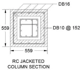
Note that in elevation views, two base columns are drawn in bold lines. From preliminary analysis, the results show localized damages on those columns due to the arrangement of BRBs. Therefore, those columns are jacketed to increase the strength capacity.
The retrofitted column section can be seen in Figure 10. Furthermore, the material properties used for concrete jacketing are same as those of original column. However, the effect of BRBs arrangement to
the building’s foundation is neglectted in this study.
Figure 10. RC jacketed column section of two base columns that are retrofitted (non-shaded area represents the original column section, all dimensions are in millimeter).
Estimating the BRBs steel core area is one of the most important steps in this scheme because it determines the additional lateral strength and Figure 8. Plan view for first floor (left) and other floors (right) of BRB building.
stiffness to the first floor. Since there is no change made for RC columns in the first floor and upper floors, thus the additional lateral stiffness needed for the first floor can be estimated from the lateral stiffness of masonry infill walls in the upper floors. Then, the BRBs steel core area can be determined to give additional lateral stiffness to the first floor so that the overall story stiffness will be approximately equal. Moreover, for story strength, since the story strength contributed from RC columns is same for all floors, then the BRBs strength can be determined from story strength contributed from masonry infill walls. However, due to strain hardening behavior which is typical characteristic of BRBs, the total lateral strength of BRBs is thus determined to be slightly lower (0.8 times) than the total lateral strength of masonry infill walls. This is done to ensure that the BRBs will yield first before masonry infill walls reach their peak strength so that the
“damage control” mechanism of BRBs will work and
they will be able to dissipate energy. Furthermore, assuming the strain hardening of BRBs is as much as 1.25 of their yield strength, thus the maximum total lateral strength of BRBs will be at least equal to the lateral strength of masonry infill walls. By doing so, soft story mechanism can be therefore avoided. The complete properties of BRBs used in this scheme are displayed in Table 3. The fundamental periods of BRB building are 0.57s and 0.50s in X and Y directions, respectively.
Analysis Results
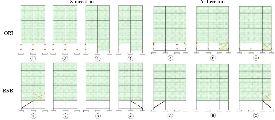
The results of seismic performance evaluation are presented in terms of maximum interstory drifts and location where damages occur during the analysis. Firstly, comparison of seismic performance of original GLD building (ORI) and the retrofitted one (BRB) under moderate earthquake is presented in Figures 11 to 13. In addition, seismic performance of BRB building under strong earthquake is presented in Figures 14 to 16 to see whether the retrofitted damage, they are symbolized as equal notation (=) at location where shear damage occurs. For beam-column joint shear damage, it is symbolized as square notation (□) at location where joint shear damage detected. For infill wall damage, it is symbolized as cross notation (x) at location where the wall is damaged. Furthermore, the lighter color (yellow in color print) represents minor to moderate damage whereas the darker color (orange in color print) represents extensive damage.
Discussions and Conclusions
Overall, as compared to the original GLD building, the seismic performance of BRB building under moderate earthquake is much better. In the case of original GLD building, the seismic performance is very poor due to soft story that exists in the first floor which attracts deformation demand to be concen-trated on the first floor. Thus, the columns and infill walls in the first floor are heavily damaged and it leads to soft story mechanism. It is likely that the original GLD building cannot survive if it is sub-jected to stronger earthquake. Therefore, the seismic performance evaluation of the original GLD building is done only for moderate earthquake. On the other hand, in the case of BRB building, it can be seen that deformation demand can be well distributed throughout the building. The maximum story drift can be reduced significantly and kept below 1% for all cases which is within acceptable limit for moderate intensity earthquake. Moreover, from damage state, the retrofitted GLD building suffers minor damages when subjected to moderate earthquake. There are only some minor damages in the BRBs and some damages in infill walls. There-fore, it can be concluded that the seismic streng-thening scheme proposed can significantly improve the seismic performance of the GLD building.
Under strong earthquake, it can be seen from the analysis results that BRB building still performs quite well although there are some differences at the
building’s responses subjected to different earthquake. The maximum story drift and building’s damages
By doing so, BRBs can limit the seismic forces acting
on RC frames and thus it results in less building’s
damages.
Another advantage of BRBs is post-earthquake repairing or rehabilitation. As can be seen in the damage state for moderate earthquake, the damages occurred in BRB building are mainly concentrated on the BRBs. This is a typical damage pattern of
“damage controlled structures” which the damages
are supposed to occur in the auxiliary structure while keeping the primary structure less damaged. Hence, after an earthquake happens, it is very easy
to restore the building’s capacity or strength by
replacing the damaged BRBs with the new ones.
Indeed, this is a major advantage of “damage controlled structures” over traditional frame struc -tures, since in traditional frame struc-tures, the damages may occur in beams, columns, beam-column joints, and infill walls and thus it needs a lot of effort to repair or rehabilitate the building in order to restore its capacity or strength after an earthquake. Therefore, due to these benefits, BRBs offer an innovative and yet effective approach for seismic strengthening of GLD RC frame buildings with a soft/weak first story.
Table 3.Properties of BRBs used in BRB building
BRB No. Yield Strength (MPa) Modulus of Elasticity (MPa) Cross Section Dimension (mm) Area (mm2)
BRB-1 320 200000 30 x 110 3300
BRB-2 320 200000 30 x 110 3300
BRB-3 320 200000 30 x 123 3690
BRB-4 320 200000 30 x 112.5 3375
Figure 11. Comparison of maximum story drift in X and Y direction of original GLD building (ORI) and BRB building (BRB) subjected to moderate SF, 1971 earthquake (left) and moderate NR, 1994 earthquake (right)
X-direction Y-direction
ORI
BRB
X-direction Y-direction
ORI
BRB
Figure 13. Comparison of damage state in X and Y direction of original GLD building (ORI) and BRB building (BRB) subjected to moderate NR, 1994 earthquake.
Figure 14. Maximum story drift in X and Y direction of BRB building subjected to strong SF, 1971 earthquake (left) and strong NR, 1994 earthquake (right).
X-direction Y-direction
BRB
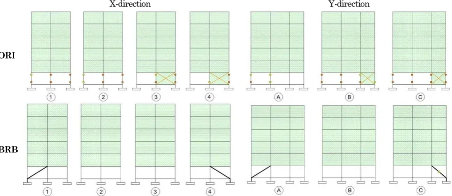
Figure 15. Damage state in X and Y direction of BRB building subjected to strong SF, 1971 earthquake
X-direction Y-direction
BRB
References
1. Huang, Y., Wada, A., Iwata, M., Mahin, S. A. and Connor, J. J., Design of Damage-Controlled Structures, In Oliveto, G., Innovative Approaches
to Earthquake Engineering, WIT Press, Ashurst,
U.K., 2001, pp. 85-118.
2. Brown, A. P., Aiken, I. D., and Jafarzadeh, F. J., Buckling Restrained Braces Provide the Key to the Seismic Retrofit of the Wallace F. Bennett Federal Building, Modern Steel Construction,
August, 2001.
3. Mazzolani, F. M., et al., Seismic Upgrading of RC Buildings by Advanced Techniques - The
ILVA-IDEM Research Project, Polimetrica Publisher,
Italy, 2006.
4. Yooprasertchai, E., Seismic Retrofitting of Low-Rise Nonductile Reinforced Concrete Buildings by
Buckling Restrained Braces (Master thesis No
ST-07-04), Asian Institute of Technology,
Bang-kok, 2007.
5. Suthasit, M., Nonlinear Modeling of Gravity Load Designed Reinforced Concrete Buildings for Seismic Performance Evaluation (Master thesis
No ST-07-06), Asian Institute of Technology,
Bangkok, 2007.
6. Suthasit, M. and Warnitchai, P., Modeling of Gravity Load Designed RC Frame Buildings for Nonlinear Dynamic Analysis, The 14th World
Conference on Earthquake Engineering, Beijing,
China, 2008.
7. Chandra, J., Seismic Retrofitting of Mid Rise Reinforced Concrete Frame Buildings with a Soft/Weak First Story Using Buckling Restrained
Braces (Master thesis No ST-09-06), Asian
Ins-titute of Technology, Bangkok, 2009.
8. Rayamajhi, D., Effects of Plan-Eccentric Infill Walls Configuration on 3D Nonlinear Response of Reinforced Concrete Frame Building (Master
thesis No ST-09-04), Asian Institute of
Techno-logy, Bangkok, 2009.
9. American Society of Civil Engineers (ASCE),
Prestandard and Commentary for the Seismic
Rehabilitation of Buildings (FEMA-356), Federal
Emergency Management Agency, Virginia, 2000.
10.Mazzoni, S., McKenna, F., Scott, M. H., Fenves, G. L., et al., Open System for Earthquake
Engi-neering Simulation (OpenSees), Pacific
Earth-quake Engineering Research Center, University of California, Berkeley, 2000.
11.http://peer.berkeley.edu/peer_ground_motion_dat abase
12.International Conference of Building Officials (ICBO), Uniform Building Code, Volume 2, Inter-national Conference of Building Officials, Califor-nia, 1997.
13.Shome, N., Cornell. A., Bazzurro. P., and Car-ballo, J.E., Earthquakes, Records, and Nonlinear Responses, Earthquake Spectra, 14(3), 1998, pp. 469-500.
14.Stewart, J. P., Liu, A. H., Choi, Y. and Baturay, M. B., Amplification Factors for Spectral Acceleration in Active Regions (PEER Report
2001/10), Pacific Earthquake Engineering
Rese-arch Center, University of California, Berkeley, 2001.
15.American Institute of Steel Construction (AISC),
Seismic Provisions for Structural Steel Buildings
(ANSI/AISC 341-05), American Institute of Steel