Computers and Structures, Inc.
Berkeley, California, USA
January 2002Version 8ETABS
®
Integrated Building Design Software
Copyright Computers and Structures, Inc., 1978-2002. The CSI Logo is a trademark of Computers and Structures, Inc. ETABS is a trademark of Computers and Structures, Inc. Windows is a registered trademark of Microsoft Corporation. Adobe and Acrobat are registered trademarks of Adobe Systems Incorporated
Copyright
The computer program ETABS and all associated documentation are proprietary and
copyrighted products. Worldwide rights of ownership rest with Computers and
Structures, Inc. Unlicensed use of the program or reproduction of the documentation in
any form, without prior written authorization from Computers and Structures, Inc., is
explicitly prohibited.
Further information and copies of this documentation may be obtained from:
Computers and Structures, Inc.
1995 University Avenue
Berkeley, California 94704 USA
Phone: (510) 845-2177
FAX: (510) 845-4096
e-mail: [email protected] (for general questions)
e-mail: [email protected] (for technical support questions)
DISCLAIMER
CONSIDERABLE TIME, EFFORT AND EXPENSE HAVE GONE INTO THE
DEVELOPMENT AND DOCUMENTATION OF ETABS. THE PROGRAM HAS
BEEN THOROUGHLY TESTED AND USED. IN USING THE PROGRAM,
HOWEVER, THE USER ACCEPTS AND UNDERSTANDS THAT NO WARRANTY
IS EXPRESSED OR IMPLIED BY THE DEVELOPERS OR THE DISTRIBUTORS
ON THE ACCURACY OR THE RELIABILITY OF THE PROGRAM.
THIS PROGRAM IS A VERY PRACTICAL TOOL FOR THE DESIGN/CHECK OF
STEEL STRUCTURES. HOWEVER, THE USER MUST THOROUGHLY READ THE
MANUAL AND CLEARLY RECOGNIZE THE ASPECTS OF STEEL DESIGN THAT
THE PROGRAM ALGORITHMS DO NOT ADDRESS.
i
©COMPUTERS AND STRUCTURES, INC., BERKELEY, CALIFORNIA DECEMBER 2001STEEL FRAME DESIGN
Contents
General Steel Frame Design Information
1 General Design Information
Design Codes 1-1
Units 1-1
Overwriting the Frame Design Procedure
for a Steel Frame 1-1
Design Load Combinations 1-2
Analysis Sections and Design Sections 1-3 Second Order P-Delta Effects 1-4 Element Unsupported Lengths 1-6 Effective Length Factor (K) 1-7 Continuity Plates and Doubler Plates 1-9
2 Steel Frame Design Process
Steel Frame Design Procedure 2-1 Automating the Iterative Design Process 2-5
3 Interactive Steel Frame Design
General 3-1
Steel Stress Check Information Form 3-1
Overwrites Button 3-4
Details Button 3-4
4 Output Data Plotted Directly on the Model
Overview 4-1
Design Input 4-1
Steel Frame Design Manual
ii
Steel Frame Design Specific to UBC97-ASD
5 General and Notation
Introduction to the UBC-ASD Series of
Technical Notes 5-1
Notations 5-3
References 5-6
6 Preferences
General 6-1
Using the Preferences Form 6-1
Preferences 6-2
7 Overwrites
General 7-1
Overwrites 7-1
Making Changes in the Overwrites Form 7-3 Resetting Steel Frame Overwrites to Default
Values 7-4
8 Design Load Combinations
9 Classification of Sections
Overview 9-1
10 Calculation of Stresses
11 Calculation of Allowable Stresses
12 Calculation of Stress Ratios
Axial and Bending Stresses 12-1
Shear Stresses 12-3
13 Seismic Requirements
Ordinary Moment Frames 13-1
Contents
iii
Braced Frame 13-2
Eccentrically Braced Frames 13-4 Special Concentrically Braced Frames 13-7
14 Joint Design
Beam/Column Plastic Moment Capacity
Ratio 14-1
Evaluation of Beam Connection Shears 14-3 Evaluation of Brace Connection Forces 14-4
15 Continuity Plates
16 Doubler Plates
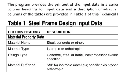
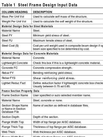
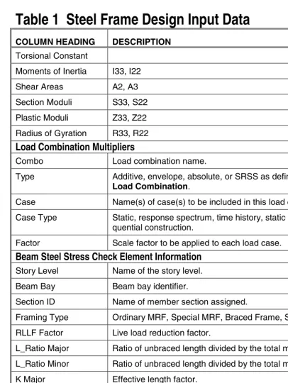
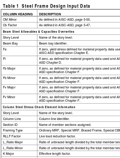
17 Input Data
Input Data 17-1
Using the Print Design Tables Form 17-5
18 Output Details
Using the Print Design Tables Form 18-4
Steel Frame Design Specific to UBC97-LRFD
19 General and Notation
Introduction to the UBC97-LRFD Series of
Technical Notes 19-1
Notation 19-3
References 19-7
20 Preferences
General 20-1
Using the Preferences Form 20-1
Preferences 20-2
21 Overwrites
Steel Frame Design Manual
iv
Overwrites 21-1
Making Changes in the Overwrites Form 21-4 Resetting Steel Frame Overwrites to Default
Values 21-5
22 Design Loading Combinations
Reference 22-2
23 Classification of Sections
24 Calculation of Factored Forces and Mo-ments
Reference 24-2
25 Calculation of Nominal Strengths 25-1
26 Calculation of Capacity Ratios
Overview 26-1
Axial and Bending Stresses 26-1
Shear Stresses 26-2
27 Seismic Requirements
Ordinary Moment Frames 27-1
Special Moment Resisting Frames 27-1
Braced Frames 27-2
Eccentrically Braced Frames 27-3 Special Concentrically Braced Frames 27-7
28 Joint Design
Weak-Beam / Strong-Column Measure 28-1 Evaluation of Beam Connection Shears 28-3 Evaluation of Brace Connection Forces 28-4
29 Continuity Plates
Contents
v
31 Input DataInput Data 31-1
Using the Print Design Tables Form 31-6
32 Output Details
Using the Print Design Tables Form 32-4
Steel Frame Design Specific to AISC-ASD89
33 General and Notation
Introduction to the AISC-ASD89 Series of
Technical Notes 33-1
Notation 33-2
34 Preferences
General 34-1 Using the Preferences Form 34-1
Preferences 34-2
35 Overwrites
General 35-1
Overwrites 35-1
Making Changes in the Overwrites Form 35-3 Resetting the Steel Frame Overwrites
to Default Values 35-4
36 Design Load Combinations
37 Classification of Sections
38 Calculation of Stresses
39 Calculation of Allowable Stresses
Allowable Stress in Tension 39-1 Allowable Stress in Compression 39-1
Steel Frame Design Manual
vi
Flexural-Torsional Buckling 39-4 Allowable Stress in Bending 39-8
I-Sections 39-8
Channel Sections 39-12
T Sections and Double Angles 39-13 Box Sections and Rectangular
Tubes 39-13
Pipe Sections 39-14
Round Bars 39-15
Rectangular and Square Bars 39-15 Single-Angle Sections 39-15
General Sections 39-18
Allowable Stress in Shear 39-18 Major Axis of Bending 39-18 Minor Axis of Bending 39-19
40 Calculation of Stress Ratios
Axial and Bending Stresses 40-1
Shear Stresses 40-4
41 Input Data
Input Data 41-1
Using the Print Design Tables Form 41-5
42 Output Details
Using the Print Design Tables Form 42-3
Steel Frame Design Specific to AISC-LRFD93
43 General and Notation
Introduction to the AISC-LRFD93 Series of
Technical Notes 43-1
Notation 43-2
44 Preferences
Contents
vii
Using the Preferences Form 44-1Preferences 44-2
45 Overwrites
General 45-1
Overwrites 45-1
Making Changes in the Overwrites Form 45-4 Resetting Steel Frame Overwrites to Default
Values 45-4
46 Design Load Combinations
Reference 46-2
47 Classification of Sections
48 Calculation of Factored Forces and Moments
Reference 48-3
49 Calculation of Nominal Strengths
Overview 49-1
Compression Capacity 49-2
Flexural Buckling 49-2
Flexural-Torsional Buckling 49-3 Torsional and Flexural-Torsional
Buckling 49-6
Tension Capacity 49-8
Nominal Strength in Bending 49-8
Yielding 49-9
Lateral-Torsional Buckling 49-9 Flange Local Buckling 49-13
Web Local Buckling 49-17
Shear Capacities 49-21
Major Axis of Bending 49-21 Minor Axis of Bending 49-22
50 Calculation of Capacity Ratios
Steel Frame Design Manual
viii
Axial and Bending Stresses 50-1
Shear Stresses 50-2
51 Input Data
Input Data 51-1
Using the Print Design Tables Form 51-6
52 Output Details
Design Codes Technical Note 1 - 1 ©COMPUTERS AND STRUCTURES, INC., BERKELEY, CALIFORNIA DECEMBER 2001
STEEL FRAME DESIGN
Technical Note 1
General Design Information
This Technical Note presents some basic information and concepts that you should know before performing steel frame design using this program.
Design Codes
The design code is set using the Options menu > Preferences > Steel Frame Design command. You can choose to design for any one design code in any one design run. You cannot design some elements for one code and others for a different code in the same design run. You can however perform different design runs using different design codes without rerunning the analysis.
Units
For steel frame design in this program, any set of consistent units can be used for input. Typically, design codes are based on one specific set of units. The documentation in this series of Technical Notes is typically presented in kip-inch-seconds units.
Again, any system of units can be used to define and design a building in this program. You can change the system of units that you are using at any time.
Overwriting the Frame Design Procedure for a Steel
Frame
The three procedures possible for steel beam design are:
General Design Information Steel Frame Design
Technical Note 1 - 2 Design Load Combinations
By default, steel sections are designed using the steel frame design procedure or the composite beam design procedure. A steel frame element qualifies for the Composite Beam Design procedure if it meets all of the following criteria:
The line type is Beam; that is, the line object is horizontal.
The frame element is oriented with its positive local 2-axis in the same direction as the positive global Z-axis (vertical upward).
The frame element has I-section or channel section properties.
If a steel frame member meets the above criteria for composite beams, it defaults to the composite beam design procedure. Otherwise, it defaults to the steel frame design procedure.
A steel frame element can be switched between the Steel Frame Design, Composite Beam Design (if it qualifies), and the "None" design procedure. Assign a steel frame element the "None" design procedure if you do not want it designed by the Steel Frame Design or the Composite Beam Design post-processor.
Change the default design procedure used for steel frame elements by se-lecting the beam(s) and clicking Design menu > Overwrite Frame Design Procedure. This change is only successful if the design procedure assigned to an element is valid for that element. For example, if you select a steel beam and attempt to change the design procedure to Concrete Frame Design, the program will not allow the change because a steel frame element cannot be changed to a concrete frame element.
Design Load Combinations
The program creates a number of default design load combinations for steel frame design. You can add in your own design load combinations. You can also modify or delete the program default load combinations. An unlimited number of design load combinations can be specified.
Techni-Steel Frame Design General Design Information
Analysis Sections and Design Sections Technical Note 1 - 3 cal Note 36 Design Load Combinations and AISC-LRFD93 Steel Frame Design Technical Note 46 Design Load Combinations for more information.
Analysis Sections and Design Sections
Analysis sections are those section properties used for a frame element to analyze the model when you click the Analyze menu > Run Analysis com-mand. The design section is whatever section has most currently been de-signed and thus designated the current design section.
It is possible for the last used analysis section and the current design section to be different. For example, you may have run your analysis using a W18X35 beam and then found in the design that a W16X31 beam worked. In this case, the last used analysis section is the W18X35 and the current design section is the W16X31. Before you complete the design process, verify that the last used analysis section and the current design section are the same using the Design menu > Steel Frame Design > Verify Analysis vs De-sign Section command.
The program keeps track of the analysis section and the design section separately. Note the following about analysis and design sections:
Assigning a line object a frame section property using the Assign menu > Frame/Line > Frame Section command assigns this sec-tion as both the analysis secsec-tion and the design secsec-tion.
Running an analysis using the Analyze menu > Run Analysis com-mand (or its associated toolbar button) always sets the analysis sec-tion to be the same as the current design secsec-tion.
Using the Assign menu > Frame/Line > Frame Section command to assign an auto select list to a frame section initially sets the analysis and design section to be the section with the median weight in the auto select list.
General Design Information Steel Frame Design
Technical Note 1 - 4 Second Order P-Delta Effects
Using the Design menu > Steel Frame Design > Select Design Combo command to change a design load combination deletes design results, but it does not delete or change the design section.
Using the Define menu > Load Combinations command to change a design load combination deletes your design results, but it does not delete or change the design section.
Using the Options menu > Preferences > Steel Frame Design command to change any of the steel frame design preferences deletes design results, but it does not delete or change the design section. Deleting the static nonlinear analysis results also deletes the design
results for any load combination that includes static nonlinear forces. Typically, static nonlinear analysis and design results are deleted when one of the following actions is taken:
9 Use the Define menu > Frame Nonlinear Hinge Properties command to redefine existing or define new hinges.
9 Use the Define menu > Static Nonlinear/Pushover Cases command to redefine existing or define new static nonlinear load cases.
9 Use the Assign menu > Frame/Line > Frame Nonlinear Hinges command to add or delete hinges.
Again note that this only deletes results for load combinations that include static nonlinear forces.
Second Order P-Delta Effects
Typically design codes require that second order P-Delta effects be considered when designing steel frames. The P-Delta effects come from two sources. They are the global lateral translation of the frame and the local deformation of elements within the frame.
Steel Frame Design General Design Information
Second Order P-Delta Effects Technical Note 1 - 5
The total second order P-Delta effects on this frame element are those caused by both ∆ and δ.
The program has an option to consider P-Delta effects in the analysis. Con-trols for considering this effect are found using the Analyze menu > Set Analysis Options command and then clicking the Set P-Delta Parameters button. When you consider P-Delta effects in the analysis, the program does a good job of capturing the effect due to the ∆ deformation shown in Figure 1, but it does not typically capture the effect of the δ deformation (unless, in the model, the frame element is broken into multiple pieces over its length). In design codes, consideration of the second order P-Delta effects is generally achieved by computing the flexural design capacity using a formula similar to that shown in Equation. 1.
MCAP = aMnt + bMlt Eqn. 1
where,
MCAP = flexural design capacity
∆
δ
Original position of frameelement shown by vertical line
Position of frame element as a result of global lateral translation, ∆, shown by dashed line
Final deflected position of frame element that includes the global lateral translation, ∆, and the local deformation of the element, δ
General Design Information Steel Frame Design
Technical Note 1 - 6 Element Unsupported Lengths
Mnt = required flexural capacity of the member assuming there is no translation of the frame (i.e., associated with the δ de-formation in Figure 1)
Mlt = required flexural capacity of the member as a result of lat-eral translation of the frame only (i.e., associated with the ∆ deformation in Figure 1)
a = unitless factor multiplying Mnt
b = unitless factor multiplying Mlt (assumed equal to 1 by the program, see below)
When the program performs steel frame design, it assumes that the factor b is equal to 1 and it uses code-specific formulas to calculate the factor a. That b = 1 assumes that you have considered P-Delta effects in the analysis, as previously described. Thus, in general, if you are performing steel frame de-sign in this program, you should consider P-Delta effects in the analysis be-fore running the design.
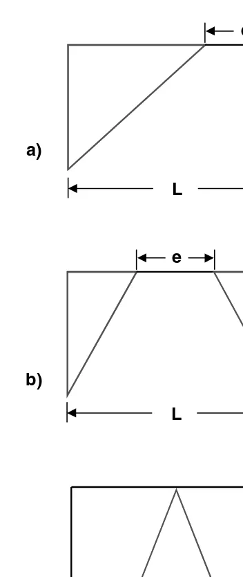
Element Unsupported Lengths
The column unsupported lengths are required to account for column slender-ness effects. The program automatically determines these unsupported lengths. They can also be overwritten by the user on an element-by-element basis, if desired, using the Design menu > Steel Frame Design > View/Revise Overwrites command.
There are two unsupported lengths to consider. They are l33 and l22, asshown in Figure 2. These are the lengths between support points of the element in the corresponding directions. The length l33 corresponds to instability about the 3-3 axis (major axis), and l22 corresponds to instability about the 2-2 axis (minor axis). The length l22 is also used for lateral-torsional buckling caused by major direction bending (i.e., about the 3-3 axis).
Steel Frame Design General Design Information
Element Unsupported Lengths Technical Note 1 - 7
It is possible for the unsupported length of a frame element to be evaluated by the program as greater than the corresponding element length. For exam-ple, assume a column has a beam framing into it in one direction, but not the other, at a floor level. In this case, the column is assumed to be supported in one direction only at that story level, and its unsupported length in the other direction will exceed the story height.
Effective Length Factor (
K
)
The program automatically determines K-factors for frame elements. These K-factors can be overwritten by the user if desired using the Design menu > Steel Frame Design > View/Revise Overwrites command. See the bulleted list at the end of this section for some important tips about how the program calculates the K-factors.
The K-factor algorithm has been developed for building-type structures, where the columns are vertical and the beams are horizontal, and the behav-ior is basically that of a moment-resisting nature for which the K-factor cal-culation is relatively complex. For the purpose of calculating K-factors, the elements are identified as columns, beams and braces. All elements parallel
General Design Information Steel Frame Design
Technical Note 1 - 8 Element Unsupported Lengths
to the Z-axis are classified as columns. All elements parallel to the X-Y plane are classified as beams. The rest are braces.
The beams and braces are assigned K-factors of unity. In the calculation of the K-factors for a column element, the program first makes the following four stiffness summations for each joint in the structural model:
x
where the x and y subscripts correspond to the global X and Y directions and the c and b subscripts refer to column and beam. The local 2-2 and 3-3 terms EI22/L22 and EI33/L33 are rotated to give components along the global X and Y directions to form the (EI/L)x and (EI/L)y values. Then for each column, the joint summations at END-I and the END-J of the member are transformed back to the column local 1-2-3 coordinate system and the G-values for END-I and the END-J of the member are calculated about the 2-2 and 3-3 directions as follows:
Steel Frame Design General Design Information
Continuity Plates and Doubler Plates Technical Note 1 - 9 from which K = π/α. This relationship is the mathematical formulation for the evaluation of K-factors for moment-resisting frames assuming sidesway to be uninhibited. For other structures, such as braced frame structures, the K-factors for all members are usually unity and should be set so by the user. The following are some important aspects associated with the column K-factor algorithm:
An element that has a pin at the joint under consideration will not en-ter the stiffness summations calculated above. An element that has a pin at the far end from the joint under consideration will contribute only 50% of the calculated EI value. Also, beam elements that have no column member at the far end from the joint under consideration, such as cantilevers, will not enter the stiffness summation.
If there are no beams framing into a particular direction of a column element, the associated G-value will be infinity. If the G-value at any one end of a column for a particular direction is infinity, the K-factor corresponding to that direction is set equal to unity.
If rotational releases exist at both ends of an element for a particular direction, the corresponding K-factor is set to unity.
The automated K-factor calculation procedure can occasionally gener-ate artificially high K-factors, specifically under circumstances involving skewed beams, fixed support conditions, and under other conditions where the program may have difficulty recognizing that the members are laterally supported and K-factors of unity are to be used.
All K-factors produced by the program can be overwritten by the user. These values should be reviewed and any unacceptable values should be replaced.
The beams and braces are assigned K-factors of unity.
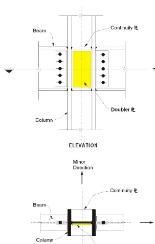
Continuity Plates and Doubler Plates
General Design Information Steel Frame Design
Technical Note 1 - 10 Continuity Plates and Doubler Plates based on a component of the beam major moment, rather than the full beam moment.
The design equations for doubler and continuity plates are described further in the following Technical Notes:
Steel Frame Design Procedure Technical Note 2 - 1 ©COMPUTERS AND STRUCTURES, INC., BERKELEY, CALIFORNIA DECEMBER 2001
STEEL FRAME DESIGN
Technical Note 2
Steel Frame Design Process
This Technical Note describes a basic steel frame design process using this program. Although the exact steps you follow may vary, the basic design pro-cess should be similar to that described herein. The other Technical Notes in the Steel Frame Design series provide additional information.
Steel Frame Design Procedure
The following sequence describes a typical steel frame design process for a new building. Note that although the sequence of steps you follow may vary, the basic process probably will be essentially the same.
1. Use the Options menu > Preferences > Steel Frame Design command to choose the steel frame design code and to review other steel frame design preferences and revise them if necessary. Note that default values are provided for all steel frame design preferences, so it is unnecessary to define any preferences unless you want to change some of the default values. See UBC97-ASD Steel Frame Design Technical Note 6 Preferences, UBC97-LRFD Steel Frame Design Technical Note 20 Preferences, AISC-ASD89 Steel Frame Design Technical Note 34 ences, and AISC-LRFD93 Steel Frame Design Technical Note 44 Prefer-encesfor more information.
2. Create the building model.
3. Run the building analysis using the Analyze menu > Run Analysis command.
Steel Frame Design Process Steel Frame Design
Technical Note 2 - 2 Steel Frame Design Procedure the analysis is run. See UBC97-ASD Steel Frame Design Technical Note 7 Overwrites, UBC97-LRFD Steel Frame Design Technical Note 21 Over-writes, AISC-ASD89 Steel Frame Design Technical Note 35 OverOver-writes, and AISC-LRFD93 Steel Frame Design Technical Note 45 Overwrites for more information.
5. Designate design groups, if desired, using the Design menu > Steel Frame Design > Select Design Group command. Note that you must have already created some groups by selecting objects and clicking the Assign menu > Group Names command.
6. To use design load combinations other than the defaults created by the program for your steel frame design, click the Design menu > Steel Frame Design > Select Design Combo command. Note that you must have already created your own design combos by clicking the Define menu > Load Combinations command. See UBC97-ASD Steel Frame Design Technical Note 8 Design Load Combinations, UBC97-LRFD Steel Frame Design Technical Note 22 Design Load Combinations, AISC-ASD89 Steel Frame Design Technical Note 36 Design Load Combinations, and AISC-LRFD93 Steel Frame Design Technical Note 46 Design Load Combi-nations for more information.
7. Designate lateral displacement targets for various load cases using the Design menu > Steel Frame Design > Set Lateral Displacement Targets command.
8. Click the Design menu > Steel Frame Design > Start Design/Check of Structure command to run the steel frame design.
9. Review the steel frame design results by doing one of the following:
a. Click the Design menu > Steel Frame Design > Display Design Info command to display design input and output information on the model. See Steel Frame Design Technical Note 4 Output Data Plotted Directly on the Model.
Steel Frame Design Steel Frame Design Process
Steel Frame Design Procedure Technical Note 2 - 3 If design results are not currently displayed (and the design has been run), click the Design menu > Steel Frame Design > Interactive Steel Frame Design command and right click a frame element to enter the interactive design mode for that element. See Steel Frame Design Technical Note 3 Interactive Steel Frame Design for more in-formation.
c. Use the File menu > Print Tables > Steel Frame Design command to print steel frame design data. If you select frame elements before using this command, data is printed only for the selected elements. See UBC97-ASD Steel Frame Design Technical Note 17 Input Data, UBC97-LRFD Steel Frame Design Technical Note 31 Input Data, ASD89 Steel Frame Design Technical Note 41 Input Data, and AISC-LRFD93 Steel Frame Design Technical Note 51 Input Data, and ASD Steel Frame Design Technical Note 18 Output Details, UBC97-LRFD Steel Frame Design Technical Note 32 Output Details, AISC-ASD89 Steel Frame Design Technical Note 42 Output Details, and AISC-LRFD93 Steel Frame Design Technical Note 52 Output Details for more information.
10. Use the Design menu > Steel Frame Design > Change Design Section command to change the design section properties for selected frame elements.
11. Click the Design menu > Steel Frame Design > Start De-sign/Check of Structure command to rerun the steel frame design with the new section properties. Review the results using the procedures described above.
12. Rerun the building analysis using the Analyze menu > Run Analysis command. Note that the section properties used for the analysis are the last specified design section properties.
13. Compare your lateral displacements with your lateral displacement tar-gets.
Steel Frame Design Process Steel Frame Design
Technical Note 2 - 4 Steel Frame Design Procedure Note:
Steel frame design in this program is an iterative process. Typically, the analysis and design will be rerun multiple times to complete a design.
15. Again use the Design menu > Steel Frame Design > Change De-sign Section command to change the deDe-sign section properties for se-lected frame elements, if necessary.
16. Repeat the processes in steps 12, 13, 14 and 15 as many times as nec-essary.
17. Select all frame elements and click the Design menu > Steel Frame Design > Make Auto Select Section Null command. This removes any auto select section assignments from the selected frame elements (if they have the Steel Frame design procedure).
18. Rerun the building analysis using the Analyze menu > Run Analysis command. Note that the section properties used for the analysis are the last specified design section properties.
19. Verify that your lateral displacements are within acceptable limits.
20. Click the Design menu > Steel Frame Design > Start De-sign/Check of Structure command to rerun the steel frame design with the new section properties. Review the results using the procedures described in step 9.
21. Click the Design menu > Steel Frame Design > Verify Analysis vs Design Section command to verify that all of the final design sections are the same as the last used analysis sections.
Steel Frame Design Steel Frame Design Process
Automating the Iterative Design Process Technical Note 2 - 5 section sizes and then run a design check using the forces obtained from that analysis. Use the Design menu > Steel Frame Design > Verify Analysis vs Design Section command to verify that the design sections are the same as the analysis sections.
Automating the Iterative Design Process
If frame elements have been assigned as auto select sections, the program can automatically perform the iterative steel frame design process. To initiate this process, first use the Options menu > Preferences > Steel Frame Design command and set the Maximum Auto Iterations item to the maximum number of design iterations you want the program to run automatically. Next run the analysis. Then, making sure that no elements are selected, use the Design menu > Steel Frame Design > Start Design/Check of Structure command to begin the design of the structure. The program will then start a cycle of (1) performing the design, (2) comparing the last-used Analysis Sec-tions with the Design SecSec-tions, (3) setting the Analysis SecSec-tions equal to the Design Sections, and (4) rerunning the analysis. This cycle will continue until one of the following conditions has been met:
the Design Sections and the last-used Analysis Sections are the same
General Technical Note 3 - 1 ©COMPUTERS AND STRUCTURES, INC., BERKELEY, CALIFORNIA DECEMBER 2001
STEEL FRAME DESIGN
Technical Note 3
Interactive Steel Frame Design
General
Interactive steel frame design allows you to review the design results for any frame element and to interactively change the design overwrites and immedi-ately review the results.
Note that a design must have been run for the interactive design mode to be available. To run a design, click Design menu > Steel Frame Design > Start Design/Check of Structure command.
Right click on a frame element while the design results are displayed on it to enter the interactive design mode and interactively design the element. If de-sign results are not currently displayed (and the dede-sign has been run), click the Design menu > Steel Frame Design > Interactive Steel Frame De-sign command and then right click a frame element to enter the interactive design mode for that element and display the Steel Stress Check Information form.
Steel Stress Check Information Form
Table 1 identifies the features that are included in the Steel Stress Check In-formation form.
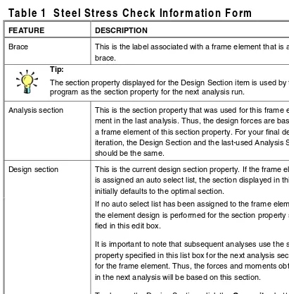
Table 1 Steel Stress Check Information Form
FEATURE DESCRIPTION
Story ID This is the story level ID associated with the frame element. Beam This is the label associated with a frame element that is a
beam.
Interactive Steel Frame Design Steel Frame Design
Technical Note 3 - 2 Table 1 Steel Stress Check Information Form
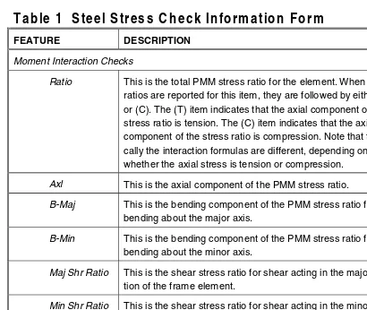
Table 1 Steel Stress Check Information Form
FEATURE DESCRIPTION
Brace This is the label associated with a frame element that is a brace.
Tip:
The section property displayed for the Design Section item is used by the program as the section property for the next analysis run.
Analysis section This is the section property that was used for this frame ele-ment in the last analysis. Thus, the design forces are based on a frame element of this section property. For your final design iteration, the Design Section and the last-used Analysis Section should be the same.
Design section This is the current design section property. If the frame element is assigned an auto select list, the section displayed in this form initially defaults to the optimal section.
If no auto select list has been assigned to the frame element, the element design is performed for the section property speci-fied in this edit box.
It is important to note that subsequent analyses use the section property specified in this list box for the next analysis section for the frame element. Thus, the forces and moments obtained in the next analysis will be based on this section.
To change the Design Section, click the Overwrites button.
Stress Details Table
The stress details table shows the stress ratios obtained for each design load combina-tion at each output stacombina-tion along the frame element. Initially the worst stress ratio is high-lighted. Following are the headings in the table:
Combo ID This is the name of the design load combination considered. Station location This is the location of the station considered, measured from
Steel Frame Design Interactive Steel Frame Design
Table 1 Steel Stress Check Information Form Technical Note 3 - 3
Table 1 Steel Stress Check Information Form
FEATURE DESCRIPTION
Moment Interaction Checks
Ratio This is the total PMM stress ratio for the element. When stress ratios are reported for this item, they are followed by either (T) or (C). The (T) item indicates that the axial component of the stress ratio is tension. The (C) item indicates that the axial component of the stress ratio is compression. Note that typi-cally the interaction formulas are different, depending on whether the axial stress is tension or compression. Axl This is the axial component of the PMM stress ratio. B-Maj This is the bending component of the PMM stress ratio for
bending about the major axis.
B-Min This is the bending component of the PMM stress ratio for bending about the minor axis.
Maj Shr Ratio This is the shear stress ratio for shear acting in the major direc-tion of the frame element.
Min Shr Ratio This is the shear stress ratio for shear acting in the minor direc-tion of the frame element.
Overwrites Button
Click this button to access and make revisions to the steel frame overwrites and then immediately see the new design results. If you modify some overwrites in this mode and exit both the Steel Frame Design Overwrites form and the Steel Stress Check Information form by clicking their respective OK buttons, the changes made to the overwrites are saved permanently.
Interactive Steel Frame Design Steel Frame Design
Technical Note 3 - 4 Table 1 Steel Stress Check Information Form
Details Button
Overview Technical Note 4 - 1 ©COMPUTERS AND STRUCTURES, INC., BERKELEY, CALIFORNIA DECEMBER 2001
S
TEELF
RAMED
ESIGNTechnical Note 4
Output Data Plotted Directly on the Model
This Technical Note describes the input and output data that can be plotted directly on the model.
Overview
Use the Design menu > Steel Frame Design > Display Design Info command to display on-screen output plotted directly on the program model. If desired, the screen graphics can then be printed using the File menu > Print Graphics command. The on-screen display data provides design input and output data.
Design Input
Table 1 identifies the types of data that can be displayed directly on the model by selecting the data type (shown in bold type) from the drop-down list on the Display Design Results form. Display this form by selecting the Design menu > Steel Frame Design > Display Design Info command.
Table 1 Data Displayed Directly on the Model
DATA TYPE DESCRIPTION
Design Sections The current design section property.
Design Type Steel, concrete or other. In this section, steel would be
selected.
Live Load Red Fac-tors
These reduction factors are used by the program to automatically reduce the live load in the design post-processor. They are set using the Options menu > Preferences command.
Output Data Plotted Directly on the Model Steel Frame Design
Technical Note 4 - 2 Design Output
Table 1 Data Displayed Directly on the Model
DATA TYPE DESCRIPTION
Effective Length K-Factors
As defined in AISC-ASD Table C-C2.1 or AISC-LRFD Table C-C2.1.
Axial Allowables
Bending Allowables
Shear Allowables
Note that you cannot simultaneously display multiple listed items on the model.
Design Output
Table 2 identifies the types of data that can be displayed directly on the model after the model has been run by selecting the data type (shown in bold type) from the drop-down list on the Display Design Results form. Display this form by selecting he Design menu > Steel Frame Design > Display De-sign Info command.
Table 2 Data Available After a Model Has Been Run
DATA TYPE DESCRIPTION
PM Ratio Colors & Values
Colors indicating stress ranges for ratio of acting axial and bending stresses or forces divided by the allowable numerical values.
PM Colors/Shear Ratio Values
Colors indicating axial and bending ratio, and numerical values indicating shear stress ratio.
PM Ratio Color/no Values
Colors indicating axial and bending ratio only.
de-Steel Frame Design Output Data Plotted Directly on the Model
Table 2 Data Available After a Model Has Been Run Technical Note 4 - 3 sign must have been run for the output selection to be available. Select P-M Ratios Colors & Values from the drop-down box. Click the OK button and your selection will display on the model in the active window. Access the other two display options in the same manner.
General and Notation Technical Note 5 - 1 ©COMPUTERS AND STRUCTURES, INC., BERKELEY, CALIFORNIA DECEMBER 2001
STEEL FRAME DESIGN UBC97-ASD
Technical Note 5
General and Notation
Introduction to the UBC97-ASD Series of Technical
Notes
The UBC97-ASD design code in this program implements the International Conference of Building Officials' 1997 Uniform Building Code: Volume 2: Structural Engineering Design Provisions, Chapter 22, Division III, "Design Standard for Specification for Structural Steel BuildingsAllowable Stress De-sign and Plastic DeDe-sign" (ICBO 1997).
For referring to pertinent sections and equations of the UBC code, a unique prefix "UBC" is assigned. For referring to pertinent sections and equations of the AISC-ASD code, a unique prefix "ASD" is assigned. However, all refer-ences to the "Specifications for Allowable Stress Design of Single-Angle Mem-bers" (AISC 1989b) carry the prefix of "ASD SAM." Various notations used in the Steel Frame Design UBC97-ASD series of Technical Notes are described herein.
When using the UBC97-ASD option, the following Framing Systems are rec-ognized (UBC 1627, 2213):
Ordinary Moment Frame (OMF)
Special Moment-Resisting Frame (SMRF) Concentrically Braced Frame (CBF) Eccentrically Braced Frame (EBF)
Special Concentrically Braced Frame (SCBF)
General and Notation Steel Frame Design UBC97-ASD
Technical Note 5 - 2 General and Notation
View/Revise Overwrites) on a member-by-member basis. If any member is assigned with a frame type, the change of the frame type in the Preference will not modify the frame type of the individual member for which it is as-signed.
When using the UBC97-LRFD option, a frame is assigned to one of the fol-lowing five Seismic Zones (UBC 2213, 2214):
Zone 0 Zone 1 Zone 2 Zone 3 Zone 4
By default the Seismic Zone is taken as Zone 4 in the program. However, the frame type can be overwritten in the Preferences to change the default (Op-tions menu > Preferences > Steel Frame Design).
The design is based on user-specified loading combinations. To facilitate use, the program provides a set of default load combinations that should satisfy requirements for the design of most building type structures. See UCB-ASD Steel Frame Design Technical Note 8 Design Load Combinations for more in-formation.
Steel Frame Design UBC97-ASD General and Notation
General and Notation Technical Note 5 - 3
Further information is available from UBC97-ASD Steel Frame Design Techni-cal Notes 9 Classification of Sections, 14 Joint Design, 15 Continuity Plates, and 16 Doubler Plates.
Information about seismic requirements is provided in UBC97-ASD Steel Frame Design Technical Note 13 Seismic Requirements.
The program uses preferences and overwrites, which are described in UBC97-ASD Steel Frame Design Technical Notes 6 Preferences and 7 Overwrites. It also provides input and output data summaries, which are described in UBC97-ASD Steel Frame Design Technical Notes 17 Input Data and 18 Output Details.
English as well as SI and MKS metric units can be used for input. But the code is based on Kip-Inch-Second units. For simplicity, all equations and descrip-tions presented in this series of Technical Notes correspond to Kip-Inch-Second units unless otherwise noted.
Notations
A Cross-sectional area, in2
Ae Effective cross-sectional area for slender sections, in2
Af Area of flange, in2
Ag Gross cross-sectional area, in2
Av2, Av3 Major and minor shear areas, in2
Aw Web shear area, dtw, in2
Cb Bending Coefficient
Cm MomentCoefficient
Cw Warping constant, in6
General and Notation Steel Frame Design UBC97-ASD
Technical Note 5 - 4 General and Notation
Fa Allowable axial stress, ksi
Fb Allowable bending stress, ksi
Fb33, Fb22 Allowable major and minor bending stresses, ksi
Fcr Critical compressive stress, ksi
'
Fv Allowable shear stress, ksi
Fy Yield stress of material, ksi
K Effective length factor
K33, K22 Effective length K-factors in the major and minor directions
M33, M22 Major and minor bending moments in member, kip-in
Mob Lateral-torsional moment for angle sections, kin-in
P Axial force in member, kips Pe Euler buckling load, kips
Q Reduction factor for slender section, = QaQs Qa Reduction factor for stiffened slender elements
Qs Reduction factor for unstiffened slender elements
S Section modulus, in3
S33, S22 Major and minor section moduli, in3
Seff,33,Seff,22 Effective major and minor section moduli for slender
Steel Frame Design UBC97-ASD General and Notation
General and Notation Technical Note 5 - 5
Sc Section modulus for compression in an angle section, in3
V2, V3 Shear forces in major and minor directions, kips
b Nominal dimension of plate in a section, in longer leg of angle sections,
bf — 2tw for welded and bf — 3tw for rolled box sections, etc.
be Effective width of flange, in
bf Flange width, in
d Overall depth of member, in
fa Axial stress, either in compression or in tension, ksi
fb Normal stress in bending, ksi
fb33, fb22 Normal stress in major and minor direction bending, ksi
fv Shear stress, ksi
fv2, fv3 Shear stress in major and minor direction bending, ksi
h Clear distance between flanges for I shaped sections (d — 2tf), in
he Effective distance between flanges, less fillets, in
k Distance from outer face of flange to web toes of fillet, in kc Parameter used for classification of sections,
[
]
h t 70,05 . 4
w 46
.
0 if >
t h w
1 if h tw ≤ 70
l33, l22 Major and minor direction unbraced member length, in
lc Critical length, in
General and Notation Steel Frame Design UBC97-ASD
Technical Note 5 - 6 General and Notation
r33, r22 Radii of gyration in the major and minor directions, in
rz Minimum radius of gyration for angles, in
t Thickness of a plate in I, box, channel, angle, and T sec-tions, in
tf Flange thickness, in
tw Web thickness, in
βw Special section property for angles, in
References
American Institute of Steel Construction (AISC). 1989a. Specification for Structural Steel Buildings: Allowable Stress Design and Plastic Design, June 1, 1989 with Commentary, 2nd Impression. Chicago, Illinois. American Institute of Steel Construction (AISC). 1989b. Manual of Steel
Con-struction, Allowable Stress Design, 9th Edition. Chicago, Illinois.
General Technical Note 6 - 1 ©COMPUTERS AND STRUCTURES, INC., BERKELEY, CALIFORNIA DECEMBER 2001
S
TEELF
RAMED
ESIGNUBC97-ASD
Technical Note 6
Preferences
This Technical Note describes the items in the Preferences form.
General
The steel frame design preferences in this program are basic assignments that apply to all steel frame elements. Use the Options menu > Prefer-ences > Steel Frame Design command to access the Preferences form where you can view and revise the steel frame design preferences.
Default values are provided for all steel frame design preference items. Thus, it is not required that you specify or change any of the preferences. You should, however, at least review the default values for the preference items to make sure they are acceptable to you.
Using the Preferences Form
To view preferences, select the Options menu > Preferences > Steel Frame Design. The Preferences form will display. The preference options are displayed in a two-column spreadsheet. The left column of the spread-sheet displays the preference item name. The right column of the spreadspread-sheet displays the preference item value.
To change a preference item, left click the desired preference item in either the left or right column of the spreadsheet. This activates a drop-down box or highlights the current preference value. If the drop-down box appears, select a new value. If the cell is highlighted, type in the desired value. The prefer-ence value will update accordingly. You cannot overwrite values in the drop-down boxes.
Preferences Steel Frame Design UBC97-ASD
Technical Note 6 - 2 Preferences
the form, any changes made to the preferences are ignored and the form is closed.
Preferences
For purposes of explanation in this Technical Note, the preference items are presented in Table 1. The column headings in the table are described as fol-lows:
Item: The name of the preference item as it appears in the cells at the left side of the Preferences form.
Possible Values: The possible values that the associated preference item can have.
Default Value: The built-in default value that ETABS assumes for the as-sociated preference item.
Description: A description of the associated preference item.
Table 1: Steel Frame Preferences
Item
Possible Values
Default
Value Description
Design Code Any code in the program
AISC-ASD89 Design code used for design of steel frame elements.
Time History Design
Envelopes, Step-by-Step
Envelopes Toggle for design load combinations that include a time history designed for the envelope of the time history, or de-signed step-by-step for the entire time history. If a single design load combi-nation has more than one time history case in it, that design load combination is designed for the envelopes of the time histories, regardless of what is specified here.
Frame Type Ordinary MRF, Special MRF, Braced Frame,
Special CBF, EBF
Steel Frame Design UBC97-ASD Preferences
Preferences Technical Note 6 - 3
Table 1: Steel Frame Preferences
Item
Possible Values
Default
Value Description
Zone Zone 0,
Zone 1, Zone 2, Zone 3, Zone 4
Zone 4 Seismic zone
Omega 0 ≥0 2.8
Stress Ratio Limit
>0 .95 Program will select members from the auto select list with stress ratios less than or equal to this value.
Maximum Auto
Iteration ≥
General Technical Note 7 - 1 ©COMPUTERS AND STRUCTURES, INC., BERKELEY, CALIFORNIA DECEMBER 2001
STEEL FRAME DESIGN UBC97-ASD
Technical Note 7
Overwrites
General
The steel frame design overwrites are basic assignments that apply only to those elements to which they are assigned. This Technical Note describes steel frame design overwrites for UBC97-ASD. To access the overwrites, se-lect an element and click the Design menu > Steel Frame Design > View/Revise Overwrites command.
Default values are provided for all overwrite items. Thus, you do not need to specify or change any of the overwrites. However, at least review the default values for the overwrite items to make sure they are acceptable. When changes are made to overwrite items, the program applies the changes only to the elements to which they are specifically assigned; that is, to the ele-ments that are selected when the overwrites are changed.
Overwrites
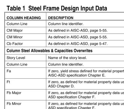
For explanation purposes in this Technical Note, the overwrites are presented in Table 1. The column headings in the table are described as follows.
Item: The name of the overwrite item as it appears in the program. To save space in the forms, these names are generally short.
Possible Values: The possible values that the associated overwrite item can have.
Default Value: The default value that the program assumes for the associ-ated overwrite item. If the default value is given in the table with an asso-ciated note "Program Calculated," the value is shown by the program before the design is performed. After design, the values are calculated by the pro-gram and the default is modified by the propro-gram-calculated value.
Overwrites Steel Frame Design UBC97-ASD
Technical Note 7 - 2 Overwrites
An explanation of how to change an overwrite is provided at the end of this Technical Note.
Table 1 Steel Frame Design Overwrites
Item
Indicates selected member size used in current design.
Element Type Ordinary MRF, Special MRF,
Live load is multiplied by this factor.
Horizontal Earthquake
Factor
≥0 1 Earthquake loads are multiplied by this
factor.
Ratio of unbraced length divided by total length.
Ratio of unbraced length divided by total length.
As defined in AISC-ASD Table C-C2.1, page 5-135.
As defined in AISC-ASD Table C-C2.1, page 5-135.
As defined in AISC-ASD, page 5-55.
Moment
Steel Frame Design UBC97-ASD Overwrites
Making Changes in the Overwrites Form Technical Note 7 - 3
Table 1 Steel Frame Design Overwrites
Item
As defined in AISC-ASD, page 5-47.
Yield stress, Fy ≥0 0 If zero, yield stress defined for material property data used.
Omega0 ≥0 From
Preferences
Seismic force amplification factor as required by the UBC.
Compressive
stress, Fa ≥
0 0 If zero, yield stress defined for material property data used and AISC-ASD specification Chapter E.
Tensile
stress, Ft ≥
0 0 If zero, as defined for material property
data used and AISC-ASD Chapter D.
Major Bending
stress, Fb3 ≥
0 0 If zero, as defined for material property
data used and AISC-ASD specification Chapter F.
Minor Bending
stress, Fb2 ≥
0 0 If zero, as defined for material property
data used and AISC-ASD specification Chapter F.
Major Shear
stress, Fv2 ≥
0 0 If zero, as defined for material property
data used and AISC-ASD specification Chapter F.
Minor Shear
stress, Fv3 ≥
0 0 If zero, as defined for material property
data used and AISC-ASD specification Chapter F.
Making Changes in the Overwrites Form
To access the steel frame overwrites, select a frame element and click the Design menu > Steel Frame Design > View/Revise Overwrites com-mand.
Overwrites Steel Frame Design UBC97-ASD
Technical Note 7 - 4 Resetting Steel Frame Overwrites to Default Values name of the overwrite item. The right column of the spreadsheet contains the overwrites values.
Initially, the check boxes in the Steel Frame Design Overwrites form are all unchecked and all of the cells in the spreadsheet have a gray background to indicate that they are inactive and the items in the cells cannot be changed. The names of the overwrite items are displayed in the first column of the spreadsheet. The values of the overwrite items are visible in the second col-umn of the spreadsheet if only one frame element was selected before the overwrites form was accessed. If multiple elements were selected, no values show for the overwrite items in the second column of the spreadsheet.
After selecting one or multiple elements, check the box to the left of an over-write item to change it. Then left click in either column of the spreadsheet to activate a drop-down box or highlight the contents in the cell in the right col-umn of the spreadsheet. If the drop-down box appears, select a value from the box. If the cell is highlighted, type in the desired value. The overwrite will reflect the change. You cannot change the values of the drop-down boxes.
When changes to the overwrites have been completed, click the OK button to close the form. The program then changes all of the overwrite items whose associated check boxes are checked for the selected members. You must click the OK button for the changes to be accepted by the program. If you click the Cancel button to exit the form, any changes made to the overwrites are ig-nored and the form is closed.
Resetting Steel Frame Overwrites to Default Values
Use the Design menu > Steel Frame Design > Reset All Overwrites command to reset all of the steel frame overwrites. All current design results will be deleted when this command is executed.
Design Load Combinations Technical Note 8 - 1 ©COMPUTERS AND STRUCTURES, INC., BERKELEY, CALIFORNIA DECEMBER 2001
S
TEELF
RAMED
ESIGNUBC97-ASD
Technical Note 8
Design Load Combinations
The design load combinations are the various combinations of the load cases for which the structural members and joints need to be designed or checked. For the UBC97-ASD code, if a structure is subjected to dead load (DL), live load (LL), wind load (WL), and earthquake induced load (EL) and considering that wind and earthquake forces are reversible, the following load combina-tions may need to be defined (UBC 1612.3):
DL (UBC 1612.3.1 12-7)
DL + LL (UBC 1612.3.1 12-8)
DL ± WL (UBC 1612.3.1 12-9)
DL + 0.75LL ± 0.75 WL (UBC 1612.3.1 12-11)
DL ± EL/1.4 (UBC 1612.3.1 12-9)
0.9 DL ± EL/1.4 (UBC 1612.3.1 12-10)
DL + 0.75 LL ± 0.75 EL/1.4 (UBC 1612.3.1 12-11)
These are also the default design load combinations in the program whenever the UBC97-ASD code is used. The user should use other appropriate load combinations if roof live load is separately treated, if other types of loads are present, or if pattern live loads are to be considered.
When designing for combinations involving earthquake and wind loads, allow-able stresses are NOT increased by a factor of 4/3 of the regular allowallow-able value (UBC 1612.3.1, 2209.3).
Live load reduction factors can be applied to the member forces of the live load case on an element-by-element basis to reduce the contribution of the live load to the factored loading. See UBC97-ASD Steel Frame Design Techni-cal Note 7 Overwrites for more information.
Design Load Combinations Steel Frame Design UBC97-ASD
Technical Note 8 - 2 Design Load Combinations
load combinations are frequently checked for specific types of members and special circumstances.
1.0 DL + 0.7 LL ±Ωo EL (UBC 2213.5.1.1.)
0.85 DL ± Ωo EL (UBC 2213.5.1.2)
where Ωo is the seismic force amplification factor, which is required to account for structural overstrength. The default value of Ωo is taken as 2.8 in the pro-gram. However, Ωo can be overwritten in the Preferences to change the de-fault and in the Overwrites on a member-by-member basis. If any member is assigned a value for Ωo, the change of Ωo in the Preferences will not modify the Ωo of the individual member for which Ωo is assigned, unless the member had been selected. The guidelines for selecting a reasonable value can be found in UBC 1630.3.1 and UCB Table 16-N. Other similar special design load combinations described in UBC97-ASD Steel Frame Design Technical Notes 13 Seismic Requirements and 14 Joint Design.
Classification of Sections Technical Note 9 - 1 ©COMPUTERS AND STRUCTURES, INC., BERKELEY, CALIFORNIA DECEMBER 2001
S
TEELF
RAMED
ESIGNUBC97-ASD
Technical Note 9
Classification of Sections
This Technical Note explains the classification of sections when the user se-lects the UBC97-ASD design code.
Overview
The allowable stresses for axial compression and flexure depend on the clas-sification of sections. The sections are classified in UBC97-ASD as either Compact, Noncompact, Slender or Too Slender in the same way as described in AISC-ASD89 Steel Frame Design Technical Note 37 Classification of Sec-tions. The program classifies the individual members according to the limiting width/thickness ratios given in Table 1 of AISC-ASD89 Steel Frame Design Technical Note 37 Classification of Sections (UBC 2208, 2212, 2213, ASD B5.1, F3.1, F5, G1, A-B5-2). The definition of the section properties required in this table is given in Figure 1 of AISC-ASD89 Steel Frame Design Technical Note 37 Classification of Sections and AISC-ASD89 Steel Frame Design Tech-nical Note 33 General and Notation.
Classification of Sections Steel Frame Design UBC97-ASD
Technical Note 9 - 2 Classification of Sections
Table 1
Limiting Width-Thickness Ratios for Classification of Sections
When Special Seismic Conditions Apply in accordance with
UBC97-ASD
(Special requirements inseismic design)
(λλλλp) Section References
bf / 2tf
(beam) ≤ 52 / Fy
UBC 2213.7.3 (SMRF) UBC 2213.10.2 (EBF)
I-SHAPE UBC 2213.9.5 (SCBF)
ASD N7
F UBC 2213.7.3 (SMRF)
UBC 2213.9.5 (SCBF)
BOX
UBC 2213.9.2.4 (SCBF)
ANGLE b / t
(brace) ≤ 52 / Fy
UBC 2213.8.2.5 (BF) UBC 2213.9.2.4 (SCBF)
DOUBLE-ANGLE b / t
(brace) ≤ 52 / Fy
UBC 2213.8.2.5 (BF) UBC 2213.9.2.4 (SCBF)
PIPE D / t
(brace) ≤ 1,300 / Fy
UBC 2213.8.2.5 (BF) UBC 2213.9.2.4 (SCBF)
CHANNEL bf / tf
hc / tw
No special requirement No special requirement
T-SHAPE bf / 2tf
d / tw
No special requirement No special requirement
ROUND BAR No special requirement
RECTANGULAR No special requirement
Calculation of Stresses Technical Note 10 - 1 ©COMPUTERS AND STRUCTURES, INC., BERKELEY, CALIFORNIA DECEMBER 2001
STEEL FRAME DESIGN UBC97-ASD
Technical Note 10
Calculation of Stresses
The axial, flexural, and shear stresses at each of the previously defined sta-tions for each load combination in UBC97-ASD are calculated in the same way as described in AISC-ASD89 Steel Frame Design Technical Note 38 Calcula-tion of Stresses without any excepCalcula-tion (UBC 2208, ASD A-B5.2d). For non-slender sections, the stresses are based on the gross cross-sectional areas (ASD A-B5.2c); for slender sections, the stresses are based on effective sec-tion properties (ASD A-B5.2c); and for Single-Angle secsec-tions, the stresses are based on the principal properties of the sections (ASD SAM 6.1.5).
The flexural stresses are calculated based on the properties about the princi-pal axes. For I, Box, Channel, T, Double-angle, Pipe, Circular and Rectangular sections, the principal axes coincide with the geometric axes. For Single-angle sections, the design considers the principal properties. For general sections, it is assumed that all section properties are given in terms of the principal di-rections.
Calculation of Allowable Stresses Technical Note 11 - 1 ©COMPUTERS AND STRUCTURES, INC., BERKELEY, CALIFORNIA DECEMBER 2001
STEEL FRAME DESIGN UBC97-ASD
Technical Note 11
Calculation of Allowable Stresses
The allowable stress in compression, tension, bending, and shear for Com-pact, NoncomCom-pact, and Slender sections in accordance with UBC97-ASD are calculated in the same way as described in the AISC-ASD89 Steel Frame De-sign Technical Note 39 Calculation of Allowable Stresses without any excep-tions (UBC 2208, ASD A-B5.2d). The allowable stresses for Seismic secexcep-tions are calculated in the same way as for Compact sections.
The allowable flexural stresses for all shapes of sections are calculated based on their principal axes of bending. For the I, Box, Channel, Circular, Pipe, T, Double-angle and Rectangular sections, the principal axes coincide with their geometric axes. For the Angle sections, the principal axes are determined and all computations related to flexural stresses are based on that.
The allowable shear stress is calculated along geometric axes for all sections. For I, Box, Channel, T, Double-Angle, Pipe, Circular and Rectangular sections, the principal axes coincide with their geometric axes. For Single-Angle sec-tions, principal axes do not coincide with the geometric axis.
All limitations and warnings related to allowable stress calculations in AISC-ASD89 Steel Frame Design Technical Note 39 Calculation of Allowable Stresses also apply when the user selects this code in the program.
Calculation of Stress Ratios Technical Note 12 - 1 ©COMPUTERS AND STRUCTURES, INC., BERKELEY, CALIFORNIA DECEMBER 2001
S
TEELF
RAMED
ESIGNUBC97-ASD
Technical Note 12
Calculation of Stress Ratios
This Technical Note explains that the stress ratios in UBC97-ASD are calcu-lated in the same way as described in AISC-ASD89 Steel Frame Design Tech-nical Note 40 Calculation of Stress Ratios, with some modifications as de-scribed herein.
In the calculation of the axial and bending stress ratios, first, for each station along the length of the member, the actual stresses are calculated for each load combination. Then the corresponding allowable stresses are calculated. Then, the stress ratios are calculated at each station for each member under the influence of each of the design load combinations. The controlling stress ratio is then obtained, along with the associated station and load combination. A stress ratio greater than 1.0 indicates an overstress. Similarly, a shear ca-pacity ratio is also calculated separately.
During the design, the effect of the presence of bolts or welds is not considered.
Axial and Bending Stresses
With the computed allowable axial and bending stress values and the factored axial and bending member stresses at each station, an interaction stress ratio is produced for each of the load combinations as follows (ASD H1, H2, SAM 6):
If fa is compressive and fa / Fa, > 0.15, the combined stress ratio is given
by the larger of
Calculation of Stress Ratios Steel Frame Design UBC97-ASD
Technical Note 12 - 2 Calculation of Stress Ratios
22
fb22 = bending stress about the local 2-axis
Fa = allowable axial stress
Fb33 = allowable bending stress about the local 3-axis
Fb22 = allowable bending stress about the local 2-axis
F'e = 2
cludes any wind load or seismic load (UBC 1612.3.1).
Cm33 and Cm22 are coefficients representing distribution of moment along the member length. They are calculated as described in AISC-ASD89 Steel Frame Design Technical Note 40 Calculation of Stress Ratios.
When the stress ratio is calculated for Special Seismic Load Combinations, the column axial allowable stress in compression is taken to be 1.7Fa
in-stead of Fa (UBC 2213.4.2).
If fa is compressive and fa /Fa ≤ 0.15, a relatively simplified formula is used
for the combined stress ratio.
22
If fa is tensile or zero, the combined stress ratio is given by the larger of
Steel Frame Design UBC97-ASD Calculation of Stress Ratios
Calculation of Stress Ratios Technical Note 12 - 3
22
(ASD H2-1). The second equation considers flexural buckling without any beneficial effect from axial compression.
When the stress ratio is calculated for Special Seismic Load Combinations, the column axial allowable stress in tension is taken to be Fy instead of Fa
(UBC 2213.4.2).
For circular and pipe sections, an SRSS combination is first made of the two bending components before adding the axial load component, instead of the simple addition implied by the above formula.
For Single-angle sections, the combined stress ratio is calculated based on the properties about the principal axis (ASD SAM 5.3, 6.1.5). For I, Box, Channel, T, Double-angle, Pipe, Circular and Rectangular sections, the principal axes coincide with their geometric axes. For Single-angle sections, principal axes are determined in the program. For general sections, it is assumed that all section properties are given in terms of the principal directions, and conse-quently, no effort is made to determine the principal directions.
In contrast to the AISC-ASD code, when designing for combinations involving earthquake and wind loads, allowable stresses are NOT increased by a factor of 4/3 of the regular allowable value (UBC 1612.3.1, 2209.3).
Shear Stresses
From the allowable shear stress values and the factored shear stress values at each station, shear stress ratios for major and minor directions are com-puted for each of the load combinations as follows:
Calculation of Stress Ratios Steel Frame Design UBC97-ASD
Technical Note 12 - 4 Calculation of Stress Ratios
For Single-angle sections, the shear stress ratio is calculated for directions along the geometric axis. For all other sections, the shear stress is calculated along the principle axes that coincide with the geometric axes.