Cataloging-in-Publication Data is on file with the Library of Congress
Copyright © 2006, 1998 by Ivana Suchy.
All rights reserved. Printed in the United States of America. Except as permitted under the United States
Copyright Act of 1976, no part of this publication may be reproduced or distributed in any form or by any
means, or stored in a data base or retrieval system, without the prior written permission of the publisher.
1 2 3 4 5 6 7 8 9 0 DOC/DOC 0 1 0 9 8 7 6 5
ISBN 0-07-146271-6
The sponsoring editor for this book was Larry S. Hager and the production supervisor was Richard C.
Ruzycka. It was set in Times Roman by International Typesetting and Composition. The art director for the
cover was Handel Low.
Printed and bound by RR Donnelley.
This book is printed on recycled, acid-free paper containing a minimum of 50% recycled, de-inked fiber.
McGraw-Hill books are available at special quantity discounts to use a s premiums and sales promotions, or
for use in corporate training programs. For more information, please write to the Director of Special Sales,
McGraw-Hill Professional, Two Penn Plaza, New York, NY 10121-2298. Or contact your local bookstore.
Information contained in this work has been obtained by The McGraw-Hill Companies, Inc. (“McGraw-Hill”)
from sources believed to be reliable. However, neither McGraw-Hill nor its authors guarantee the accuracy or
completeness of any information published herein and neither McGraw-Hill nor its authors shall be
responsible for any errors, omissions, or damages arising out of use of this information. This work is
published with the understanding that McGraw-Hill and its authors are supplying information but are not
attempting to render engineering or other professional services. If such services are required, the assistance of
an appropriate professional should be sought.
BASIC DIE DESIGN AND
DIE-WORK INFLUENCING
FACTORS
1-1
SHEET-METAL STAMPING IN COMPARISON
WITH OTHER METAL FABRICATING PROCESSES
In today’s practical and cost-conscious world, sheet-metal parts have already replaced many expensive cast, forged, and machined products.
The reason is obviously the relative cheapness of stamped, or otherwise mass-produced parts, as well as greater control of their technical and aesthetic parameters. That the world slowly turned away from heavy, ornate, and complicated shapes, and replaced them with functional, simple, and logical forms only enhanced this tendency. Remember old bath-tubs? They used to be cast and had ornamental legs. Today they are mostly made of coated sheet metal, if not plastics. Manufacturing methods for picture frames, chandeliers, door and wall hardware, kitchen sinks, pots and pans, window frames, and doors were gradually replaced by more practical and less costly techniques.
But, sheet-metal stampings can also be used to imitate handmade ornamental designs of previous centuries. Such three-dimensional decorations can be stamped in a fraction of time the repousséartist of yesterday needed.
Metal extrusions, stampings, and forgings, frequently quite complex and elaborate, are used to replace handmade architectural elements. Metal tubing, metal spun products, formings, and drawn parts are often but cheaper substitutes of other, more expensive merchandise.
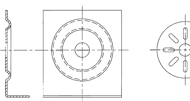
Metal stampings, probably the most versatile products of modern technology, are used to replace parts previously welded together from several components. A well-designed sheet-metal stamping can sometimes eliminate the need for riveting or other fastening processes (Fig. 1-1). Stampings can be used to improve existing designs that often are costly and labor-intensive. Even products already improved upon, with their production expenses cut to the bone, can often be further improved, further innovated, further decreased in cost.
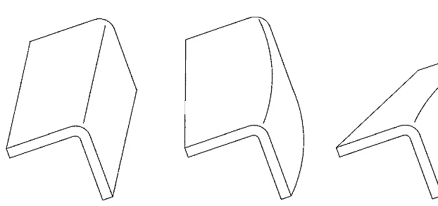
The metal stamping die(Fig. 1-2) is an ideal tool that can produce large quantities of parts that are consistent in appearance, quality, and dimensional accuracy. It is a press tool capable of cutting the metal, bending it, drawing its shape into considerable depths, embossing, coining, finishing the edges, curling, and otherwise altering the shape and the outline of the metal part to suit the wildest imaginable design concepts. Figure 1-3 shows samples of these products.
The word “die” in itself means the complete press tool in its entirety, with all the punches, die buttons, ejectors, strippers, pads, and blocks, simply with all its components assembled together.
When commenting on these little technical ingenuities, it is important to stress the role of designers of such products, both artistic and technical. Their thorough knowledge of the manufacturing field will definitely enhance not only the appearance, but the functionality, overall manufacturability, and cost of these parts.
2 CHAPTER ONE
FIGURE 1-1 Threaded part, replaced by other, less expensive means.
BASIC DIE DESIGN AND DIE-WORK INFLUENCING FACTORS 3
Metal stamping die production output can be enormous, with huge quantities of high-quality merchandise, as shown in Figs. 1-3 and 1-4; pouring forth from the press. For that reason technical ignorance is not readily excusable, as the equal quantities of rejects can be generated just the same way.
1-1-1 Grain of Material
Often, parts produced by various manufacturing methods can be redesigned to suit the sheet-metal mass production (Fig. 1-5).
FIGURE 1-3 Various sheet-metal products.
When designing such replacements, there are several aspects to be evaluated. The first and probably the most important is the grain of material (Fig. 1-6).
Sheet metal of every form, be it a strip or a sheet, displays a definite grain line. It is the direction along which the material was produced in the mill-rolling process. In coils, the grain direction always runs lengthwise, parallel with the longer edge. The grain direction
4 CHAPTER ONE
FIGURE 1-5 Additional sheet-metal replacements.
in sheets may vary, and designers must always make themselves familiar with it prior to planning a production run of any kind.
In contrast, cast or forged parts display a different grain direction, and in sintered pow-der metal parts the grain is completely gone. For this reason, each of these manufacturing methods can be used to produce items for different applications.
For example, a part, shown in Fig. 1-7, will display a different reaction to various forces and stresses when made by the forging method than when obtained through other manu-facturing processes.
Where the forging would possess a great resistance to tensile and compressive forces along the A-Aline, the same part, when made from sintered powder metal, may break or collapse under the same force.
With this shape being cast, the location of the gate is of extreme importance, as it influ-ences the part’s sturdiness in various directions. In the casting gated at the longer end (as pictured in Fig. 1-7b), the opposite end will be more susceptible to breakage, as the molten metal will reach that portion later, when already cooling down. The existence of an open-ing in that area will divide the flow of material and thus create a so-called knit line, along which a separation, resulting in defects and possible breakage, may occur.
The same casting, when gated in the middle (Fig. 1-7c), will have an equal breakage proneness at both ends. However, these ends will be somewhat sturdier, as the molten metal will reach them sooner than in the case of Fig. 1-7b. Of course, the existence of openings may have the same detrimental effect described earlier.
A similar product, made of sheet metal, as pictured in Fig. 1-8, will also display a grain-dependent behavior; the part with the lengthwise grain will be considerably sturdier along the A-Aline of force than the same shape positioned across the grain line.
Where used sensibly, the grain in sheet-metal material can serve as a backbone of future products. In formed parts where bends are oriented perpendicularly to the grain of mater-ial, such bends are rarely seen cracking or becoming distorted, and the whole structural BASIC DIE DESIGN AND DIE-WORK INFLUENCING FACTORS 5
consistency of the part is greater. Where such bends “across the grain” cannot be achieved, bends under an angle should be attempted (see Fig. 1-9). In parts with bends in both direc-tions (Fig. 1-9b), a 45°deviation from the grain line can be extremely helpful.
Aside from other advantages, sheet-metal parts are stronger and sturdier than parts pro-duced by many other manufacturing methods. For example, die cast parts can be impres-sive with their intricate shapes, nonconcentric rounds, and full-bodied mass. But they have no distinct grain direction, and where strength is required their increased thickness often serves as a substitute for sturdiness (see Fig. 1-10).
6 CHAPTER ONE
FIGURE 1-8 Grain variation in sheet-metal strip.
Sintered metals have no grain-generated backbone at all and may fail if used in high-stress applications. Forged materials do have their strength and sturdiness, but this is, again, outweighed by their bulkiness, as shown in Fig. 1-11a. Same with extruded materials (Fig. 1-11b): the grain is there, the strength is there, the columnar strength is impressive, but the increased bulkiness cannot be overlooked. Additionally, the span of applications for these products is limited and highly specific.
Plastic parts, similarly to cast products, have but the material flow to depend on and that provides them with more defects than support. And since plastic materials are generally of BASIC DIE DESIGN AND DIE-WORK INFLUENCING FACTORS 7
FIGURE 1-9 (Continued)
quite low strength when compared to metal parts of the same shape, they suffer from crack-ing when stressed or flexed, often brittle, pestered with serious agcrack-ing problems, and greatly affected by weathering effect. They are almost useless in many applications where sheet metal can substitute for them with ease. Yet, for some reason, today’s manufacturers often go into extremes of supporting a fragile plastic insert with a sturdy wire mesh or producing a complicated sheet-metal structure covered by a plastic wrapper, just to be able to use plastics. Where fillers are used in plastics moldings, the proneness of such parts to cracking can be greatly enhanced, with dependence on the percentage of filler material utilized. And considering the pressure today’s plastic parts’ production places on the petroleum industry, we actually may have no plastic parts to speak of 50 years down the road, especially when taking into account the enormity of our mass production and mass consumption.
1-1-2 Edge Formation
Another important aspect to be considered when designing sheet-metal replacements for parts manufactured by other methods is the formation of the edge. A cast part (Fig. 1-12a) will always exhibit a parting line to some degree. The visibility of this line is dependent on tool quality; with well-manufactured and well-maintained tooling, the line can be almost invisible, but with worn-out dies, rough machining, and crude assembly and fit, that area may bulge out and perhaps even show a burr at some places. The existence of draft angle in cast parts is another necessity the designer has to take into account.
If the same part were forged, it will have the edge characteristics similar to those of its cast counterpart. Sheet-metal products’ edges will be completely different. With depen-dence on the thickness of material and clearance between the punch and die, the sheet-metal parts’ cut or pierced edges will show a reasonably straight portion, with a slight distortion toward the surface opposite from the punch, as shown in Fig. 1-13. The mechanism prompt-ing such distortion to emerge at all, along with the factors contributprompt-ing to its width and volumnar growth, are explained in greater detail in Chap. 2.
Considering the terminology, here the word “die” describes the insert, which during the operation of the press receives the punch and retains the pierced slug or blanked part. Sometimes the term “die button” may be used interchangeably.
The burr on metal-stamped products is a great aid in evaluating the sequence of the manufacturing process, as it clearly indicates the direction of punching (or blanking) of each opening and of each cut.
8 CHAPTER ONE
Drawn parts’ edges are similar in that they display the characteristics of the cut metal, where produced from previously blanked material (see Fig. 1-14a). This is due to the action of blankholder, which retains the outer rim of the blank, while the middle of it is being drawn into depth.
BASIC DIE DESIGN AND DIE-WORK INFLUENCING FACTORS 9
FIGURE 1-12 Side view of the cast product.
Where no blankholder is employed, the drawn part is usually expelled through the die right after drawing, in a single, continuous motion of the press. The edges of such a part are wavy and uneven, as shown in Fig. 1-14b.
A drawn cup produced from a blankholder-restrained blank and trimmed afterwards, retains a portion of the outer radius of the previously formed flange, which gives the edge of a shell a knife-resembling sharpness (see Fig. 1-14c).
The formation of the cross section of the drawn portion further influences the product’s characteristics. There is often some thinning of the wall due to the drawing process, and the deeper the draw, the thinner the wall may become (Fig. 1-15).
10 CHAPTER ONE
FIGURE 1-14 Edge formation in drawn parts.
The reason for this is obvious: The material needed for the expanded length of the drawn portion has to be taken from somewhere, and practically (and mathematically) the volum-nar content of that section must be equal to that portion of the flat piece from which it was produced.
1-2
WHAT CONSTITUTES SUITABILITY
FOR DIE PRODUCTION?
When evaluating a part for die production, the most restrictive aspect to be considered is the cost of the tooling. To build a metal stamping die is a costly process, involving many people, many machines, and several technologies. For that reason, the demand for tooling must first be economically justified.
The quantitative demands per given time span should be evaluated first, because a sce-nario of 50,000 washers to be delivered each month requires a different treatment from 50,000 washers to be delivered each week.
A correct evaluation of the problem must be performed on the basis of:
• Availability of the appropriate press • The equipment’s running speed • The length of production shifts • Scheduling for the needed time interval
For a small run with few repetitions, a single line of tooling may be chosen. However, if the quantities are large and the time constraint exists, a multiple-part-producing tool must be built. Such a die, generating at least two or more complete parts with each stroke of a press, will speed up production admirably. But increasing the size of the tool necessitates the use of a larger and more powerful press and may even require a nonstandard width of a strip, which will certainly cost more and will have longer lead (i.e., delivery) times.
With parts other than simple washers, the shut height of the press versus the height of the part (and subsequently the height of the die) is another production-influencing factor. The width of the opening in the press plus the width of the proposed die must definitely be in congruence.
The possibility of reorders should be considered at this point, as they may result in an extended production run, greater material demands, and longer occupancy of the press. Such longer runs are usually beneficial from the economical standpoint, as they save on die-mounting procedures and press adjustments, while also decreasing the demand for quality control personnel involvement.
On the other hand, a problem of storage of these extra parts may arise along with the exis-tence of temporarily unrewarded financial investments into the purchase of material, work-force compensation, taxes, utilities, and overhead. These all need to be taken into account since they will only increase the final cost of the product, long before it can be sold to a customer.
To properly evaluate the situation, all applicable expenditures should be added up as follows:
1. Cost of the storage space (prorated rent or property taxes, cost of the building and improvements)
2. Cost of all packaging and repackaging material, storage containers, protective barriers, and insulation
3. Cost of stacking and restacking of parts, sorting them out, and discarding rusty or dam-aged pieces
4. Spoilage of possible storage-sensitive material and the scrap rate
5. Cost of raw material and other production-related necessities
6. Overhead, such as electricity, cost of heating or cooling, water, and fuel applicable to the storage of parts
7. Cost of labor, including possible overtime
8. Cost of paperwork involved with storage and subsequent handling of products
9. Interest rate at which the monies allocated to the above activities could have generated when invested otherwise
The combined expenses 1 through 9, when added up, should be equal to or less than the combined:
1. Cost of the removal of a die from the press
2. Cost of the installation of a die in the press (for the subsequent run)
3. Cost of the machine’s downtime during the die removal and installation
4. Cost of the press operator’s standby, if applicable
5. Cost of the press adjustments and trial runs
6. Cost of the first piece inspection and the cost of further adjustments and approvals, if applicable
7. Cost of the extra material and supplies, which must be purchased ahead of the time even if not immediately utilized
8. Overhead, such as cost of electricity, heating, cooling, water, and fuel
9. Cost of all subsequent billing and paperwork
10. Combined interest (per going rate) the finances allocated to the above causes would have generated when invested otherwise
The length of each run and its influence on the need for sharpening and maintenance of tool-ing must be evaluated for the entire production run. Should a maintenance-related interruption be necessary, a possible split of the previously planned combined run should be considered.
A definite advantage of the die production is its unrivaled consistency in the products’ quality and dimensional stability. In absence of design and construction mistakes, the die, once built, needs minimal amount of alterations, aside from regular sharpening.
Some dies, true, are more sensitive than others, which is mostly attributable to exces-sive demands on close tolerance ranges of parts and on the variation in material thickness. With some bending and drawing operations, the consistency in hardness of stock can be essential as well. But a regular die, well designed and well built, can deliver a great load of products before its punches begin to wear and a need for repair or sharpening arises.
Generally, it may be claimed that if the conditions of the die-operating process are kept the same and if the tool was not dropped off the forklift or similarly mangled, the parts from the die will emerge consistent with previous runs.
1-3
DESIGN CRITERIA FOR
DIE-MANUFACTURABLE PRODUCTS
Today’s world places greater and greater demands on products and materials, from which they are made. Years ago, many designers never figured out stress and strain, elasticity, fatigue, or similar values. If it broke, then you just made it 2 inches thicker, or 3 inches, or 5 inches, whatever you preferred.
But that is not how current manufacturing is governed. Resources are getting scarcer, perhaps even limited in some cases, and designers are forced to economize. After all, why should a car body be thick and heavy, when a thinner-gauge galvanized or galvannealed steel will bring about the same, if not better, results.
Demands for special alloys are continuously expanding, and they are in equal com-petition with all the new and increasingly better alloys that are being produced. Ferrous and nonferrous alloys, titanium and its and alloys, and alloys with traces of rare metals added for additional qualities are all available to fill that specific gap where they are needed.
Manufacturing methods are next on the list of economizing designers. Avoiding sec-ondary operations whenever possible, designers apply cost-conscious strategies and plan-ning not only in small shops, but in medium and large plants as well.
This certainly is a good approach to any given problem, since every product has its price. If manufacturing costs become greater than the value of a product, such an item becomes unsalable.
For these reasons, manufacturability of products is extremely important. Almost any-thing can be manufactured somehow, if people put their minds to it. But at what cost? And who will be willing to pay for it?
Out of this ever-present regard for price versus actual value, new methods are being devised daily, new approaches to old problems sought for. Crowds of engineers, designers, tool makers, model makers, and representatives of other professions are nit-picking new, almost new, or old problems, in an attempt to come up with a simple, straightforward, and cost-effective answer.
Sometimes, however, shortcuts are taken, where cheaper materials, thinner coatings, less durable tools, or less experienced labor are used. These steps are just what they present themselves as: shortcuts. They usually produce more returns, more repairs, more problems around their drawbacks, and even more expenses. There is a time and a place for every-thing, but these remedies are not always helpful. You pay for them later.
A good, sound design and overall manufacturability cannot be replaced by trinkets. The old saying “if it isn’t good, fix it” should perhaps be replaced by “if it isn’t good, redesign it!”
1-3-1 Manufacturability Aspects
The manufacturability of products depends on many factors. Sometimes a lack of space may prevent a mechanic from reaching the area of concern, and long hours may be lost before this obstacle is overcome. Or a wrong sequence of operations will cause the final product to become distorted. Sometimes an adhesive may not hold because the part was not degreased enough, or a screw may fall out because someone forgot to add that second nut or a drop of Loctite.
In die work, the manufacturability of parts is dependent on much narrower range of influences. The main areas of concern are
1. Grain direction of the material
2. Openings, their shape and location
3. Bends and other three-dimensional alterations to the flat part, their shape and location
4. Outline of the part and its size
5. Applicable tolerance ranges
6. Surface finish, flatness, straightness, and burr allowance
1-3-1-1 Grain Direction of the Material. The ever-present grain of material must be taken into consideration first. Unless absolutely necessary, it should not appear alongside a bend, a joggle, or any other deflection and elevation in the part’s surface.
Every sheet-metal material behaves differently alongside the grain line and across it. Forming, drawing, and even simple punching may sometimes show differences in the size and shape of the hole when evaluated for the grain influence. An extruded opening, shown in Fig. 1-16, illustrates this claim. By cutting across the grain line, the material behaves almost as if constantly in tension, which, when forcibly removed by the cutting process, causes the material to back off.
If a bracket such as the one shown in Fig. 1-17awill be rotated 90°and positioned on the strip with its bends along the grain line, these flanges may sometimes crack in forming or even much later, in service, afterward. For that reason, wherever the problem of multi-ple bends occurs and there is no chance of avoiding their placement alongside the grain line, an angular positioning on the strip or sheet, shown in Fig. 1-17b, should be considered.
Such a grain-line pattern should be used quite habitually with materials of the 6061-T4 (T6) aluminum group, as they are prone to cracking. Especially if, for some reason, parts are belt-sanded in flat prior to bending, their proneness to cracking will be enhanced. A greater bend radius, as well as vibratory sanding, or belt-sanding under an angle, may help to alleviate the problem to a degree.
In parts with several formed sections, the shear strength and resistance to columnar stress of their flanges will vary with their variation from the material’s grain, as shown in Fig. 1-18. Should a force A,parallel with the grain line, be applied to the bend-up section, the greatest shear strength will be encountered. However, we already know that bends run-ning parallel with the bend line are prone to cracking in forming and are not recommended. Intermediate shear strength will be encountered in the direction of the Cforce line in Fig. 1-18a, whereas the Bforce line will display the least shear strength, as the flange may tend to bend under it. Whenever a bent-up flange is acted upon by a secondary bending force, it has a tendency to follow that force’s direction only if consistent with the initial movement of the flange in forming. A force applied against the direction of bending will not flatten the material, but will break it.
14 CHAPTER ONE
BASIC DIE DESIGN AND DIE-WORK INFLUENCING FACTORS 15
FIGURE 1-17 Grain direction in formed sheet-metal parts.
Bending style shown in Fig. 1-18b, with flanges at 45°off the grain line, is considered a fair practice.
The value of the bend radius is another factor influencing the part’s behavior in forming––the smaller the radius, the greater the material’s proneness to cracking. There is a certain minimal bend radius for various materials and thicknesses, which is discussed in Chap. 8.
1-3-1-2 Openings, Their Shape and Location. Openings in the part should not be located too close to each other and certainly not too close to the edge of the sheet or strip (Fig. 1-19). At this point, it should suffice to compare the sheet-metal cutting operation to that of slicing a block of Swiss cheese. The closer to each other the cuts are placed, the more distorted they will be.
The shape of openings other than rounded, has a considerable effect on the part’s behavior in further manufacturing as well as in service (Fig. 1-20). Sharp edges in cutouts become the points of accumulated stresses and may turn into points of failure. Sharp edges are also difficult to protect from rust and corrosion, which may seep into the part through these areas. For that reason, rounded edges are preferable whenever possible.
Some minimal dimensions for punched parts are shown in Fig. 1-21. Should an open-ing be located too close to a bend, the recommended practice would be to first produce the bend and only subsequently to pierce the opening. By following this procedure, a greater dimensional stability can be achieved. Because if such an opening is pierced first and the bend produced afterward, distortion of the opening will occur (Fig. 1-22).
1-3-1-3 Bends and Other Three-Dimensional Alterations to the Flat Part, Their Shape and Location. The location of formed portions and their dependence on the direction of grain was already addressed in Sec. 1-3-1-1. In some situations, however, bending along all four edges of a square or rectangular opening cannot be avoided. This is a condition in which the results of bending along the grain and bending perpendicularly to it differ. There are charts and guidelines ready to provide us with the data on the size of the bending radius and bending allowance in either situation. But often, a simple trial run and a careful exam-ination of the bend may serve the purpose.
A slightly different problem is the formation of flanges (i.e., sides) in a four-sided enclo-sure. Here a question of the most suitable joining technique of side flanges is often brought up. Often, the sides of such a unit can be left with a small gap for welding (Fig. 1-23a), or be provided with an additional bent-up flange and spotwelded together (Fig. 1-23b).
16 CHAPTER ONE
Where the enclosure has not only four sides but the frontal, or face flanges as well (Fig. 1-23c, d, e), this dilemma is still greater. Basically, there are but three solutions to this problem. For face plates, the gaps between the joining flanges can be weld-filled and sanded smooth. For unexposed areas, or where another plate is to be used as a cover, rough-sanding to flatten the surface may be good enough.
Gaps between the flanges may be large, small, or almost nonexistent. Their size and quality depends on the bend calculation, condition of tooling, and experience of the opera-tor (in manual bending situations).
All bent-up portions should be provided with proper bend relieves (Figs. 1-24 and 1-25). These not only ease the bending process but also prevent the material from being pulled in the wrong direction, wrinkled, or torn.
BASIC DIE DESIGN AND DIE-WORK INFLUENCING FACTORS 17
FIGURE 1-20 Openings other than round.
18 CHAPTER ONE
FIGURE 1-24
20 CHAPTER ONE
On occasions where all sides of a box are to be butted against each other, a circular bend relief can sometimes be utilized. A sample of such bend relief is shown in Fig. 1-25. Here the round cutout removes that portion of material that would have been severely damaged by the bending operation.
In Fig. 1-26, some additional types of bend reliefs are shown. The most common style (Fig. 1-26b) is widely prevalent throughout the sheet-metal industry. However, even bend-ing techniques such as those marked “incorrect” in Fig. 1-26cand 1-26dmay sometimes be utilized in combination with an aggressively spring-backed pressure pad. Sometimes there would be no tear marks, cracks, or distortion visible on such parts, unless the cir-cumstances were extreme. But years later, already in service, the usually sturdy sheet-metal products may fail and break down because of the insidious and destructive effect of non-relieved stresses, created by a harsh bending process.
1-3-1-4 Outline of the Part and Its Size. Razor-sharp edges (or feather edges) must be avoided, especially if the parts are to be further handled by hand. These types of cuts are detrimental to the tooling as well, for if a punch does not engage the majority of its surface area in cutting, it tends to lean toward one side, breaking afterward. Figure 1-27 shows examples of edge trimming.
In metal stamping, feather edges may result in formation of chips and small break-offs, which tend to remain on the die surface and impair further work. These little pieces of metal may scratch the advancing strip, may become embedded in finished parts, forced into their surface by the die operation, or may even be randomly flung around, endangering the shop personnel.
Often, it may be quite tempting to use a round punch for a half-round cutout, as shown in Fig. 1-27c, or fudge the edges as in Fig. 1-27e, especially if there is a small strip of material between the part and the edge of the strip. Sometimes we just want to believe that this little sliver of metal will form an adequate support and prevent the punch from swaying aside. However, the width of the strip may come from the mill on a minus tolerance side and BASIC DIE DESIGN AND DIE-WORK INFLUENCING FACTORS 21
instead of full round cut, the punch may break through the edge and create featheredge on both sides of the cut (see Fig. 1-27d). And even where enough material was left for that pur-pose, it may be an economically unjustified waste to utilize it just for scrap. In these cases a special-shaped tool is a necessity, which will pay for itself in lesser tool damage, greater con-sistency of scrap-free production, and diminished impairment to the part and the die as well. When evaluating the outline of a part, designers should also beware of phantom bends (Fig. 1-28), and for that reason a flat layout of every bent-up part should be produced prior to any design work.
Phantom bendsare those which appear to be correct on the bent-up drawing, but actu-ally cannot be produced for various reasons. Most often there is not enough material to form the bent-up portions, or a section of the part interferes with another. These flaws are not always obvious from the part’s drawing, especially where the product is complex in shape. An accurate flat layout not only provides for spotting these problems beforehand, it also displays the extent of their interference and presents possible solutions.
Additionally, flat layouts are important for a proper assessment of the size of a blank, as shown in Figs. 1-29 and 1-30. Where a part itself may often seem small, its blank may be considerably larger than anticipated. This is most often caused by the size and location of scrap areas, attributable either to the part’s shape, or to the method of bending. If the part-forming procedure is not specified on the drawing, manufacturers may feel free to combine bends and seams to suit production practices. These alterations allow for a manipulation of the shape of the blank, shown in Fig. 1-30. By changing the blank outline, while still pro-ducing the same formed part, more economical arrangements may be arrived at.
22 CHAPTER ONE
23
FIGURE 1-28
24 CHAPTER ONE
FIGURE 1-29 Formed part and its flat layout.
However, in sheet-metal stamping, many scrap areas may be decreased, if not minimized, just by rearranging parts on the strip (Fig. 1-31). Naturally, the size of the resulting strip, and consequently the size of the die must be kept in mind in the course of such evaluation.
1-3-1-5 Applicable Tolerance Ranges. Unreasonable tolerancing demands may cause a many good die designs to turn into failures. Tolerance ranges that are too tight or out of ordinary may increase the demands for sharpening of tooling, multiply the need for addi-tional fine-finishing operations, increase the cost of a strip material, and stifle the produc-tion floor in many other ways.
What are such unreasonable tolerancing demands? These are all those that are impossible to achieve in a die work or a sheet-metal work in general. A ±.005 in. [0.13 mm] tolerance applied to a distance of an opening’s center off the edge may be considered one of them. Quite often, it cannot even be measured. After all, how do we determine where the edge starts? Is it at the upper surface of the material, or at the burr side? The burr itself may some-times amount for the total, if not more, of such tolerance. Is the edge from which we are measuring straight, or is it slightly off the parallel? Where is the hole center? It is certainly BASIC DIE DESIGN AND DIE-WORK INFLUENCING FACTORS 25
not firmly specified by a point in the midst of an opening, for which reason it is mostly deduced from the measurable diameter of that hole. Now, how do we know that the hole is completely round? What if it is minutely irregular? What if it is skewed? What if we are picking a burr or a notch instead of hole diameter?
Some may resort to giving the distance off the edge of the part to the edge of the open-ing, which is an invitation to a host of other problems. What if, for example, the punch is not exactly the size it should be? It will certainly affect the measurement greatly. And if the punch is the correct size, how do we know the tolerance between the punch and die did not affect the hole size or formation of its edge? What if we are not measuring exactly on the center line of the opening but slightly off, few degrees up or down?
These and many other questions may often puzzle designers, quality control inspectors, and production engineers, where the regular die-production problems and challenges are further enhanced by unreasonable tolerancing demands.
Another example can be seen in a ±.005 in. [0.13 mm] between two openings. This is considered a regular tolerance range of most NC turret presses. Dies can do better than that. But what if those openings are spaced 12 in. [305 mm] apart? How would the tolerance range fare at that distance? What kind of temperature is specified for such measurement to take place at? The thermal expansion coefficient of metal material can do wonders when it comes to accuracy.
We may also have a case where a ±.005 in. [0.13 mm] tolerance range is prescribed after the product has been subjected to the welding or brazing process. We all know that these operations can alter the material in many ways. These may cause it to expand, to warp, twist, or otherwise distort. In this case, even a slight expansion, warpage, or twist will instanta-neously bring us out of the given tolerance range.
Tolerance ranges are there to help us. They should not be used to act as hindrances. We must bear in mind that more stiff requirements for a hole-to-hole dimensioning may require shaving of that opening, which is an additional operation, an additional station in a pro-gressive die, and an additional cost. We must realize that a very tight tolerance range on a bend in soft metal is useless, if that bend can be further affected by the pressure of bare hand. These and many other tolerance applications must be carefully scrutinized by design-ers and judged on the basis of their adherence to the two basic manufacturing principles: common sense and work experience.
1-3-1-6 Surface Finish, Flatness, Straightness, and Burr Allowance. As can be deduced from the preceding section, tolerance ranges on flatness, straightness, and burr size vary with application. Where a greater distortion is allowable for one product, it may totally ruin the functionability of another part.
Surface flatness and straightness, as specified by the manufacturer of raw materials, may not always be adequate for our needs. The rule of thumb is, where more than generally obtain-able criteria are specified, these can most often be achieved, at an additional cost. Each and every ±.001 in. [0.025 mm] of tightened tolerance range caries along a price tag. If a product is not straight enough, it can be somewhat straightened by sizing, or flattened by grinding. Where openings are too finely dimensioned and toleranced and a burr is inexcusable, holes can be repunched, shaved, or even redrilled/milled. Welds can be ground almost invisible, edges can be sanded absolutely smooth, and parts can be polished to perfection––all that, at a cost.
Surface finish is another aspect that affects the production results extensively. How fine a surface of a product has to be? Is it but cosmetic fineness the designer is seeking, or is it a functional smoothness? Are nicks and scratches allowed on the inner (hidden) surface of the part? How many openings are to be masked prior to painting?
With unpainted products, do we know how many parts can be placed in a barrel before they will become ruined by their own weight and by the shuffle during the transport? Was packaging, designed for transport of sensitive elements properly tested? How about a drop test––is it performed routinely, or is it routinely ignored?
Products, even where arranged in layers and separated by protective barriers, can still become damaged in transport. Already the fact that one part’s sharp edge can dig into the face surface of another, or that parts may be rubbing against each other, bends in nonhard-ened materials may become further “adjusted”––these little treacheries have to be taken into account long before the first production run is delivered to the customer.
At the same time, where additional packaging requirements arise long after the quote has been submitted to the customer and accepted, these are increasing our own manufacturing expenses. Disposable packaging versus returnable barrels or crates includes a hefty sur-charge in the difference between the two. Protective wrapping, “egg crating,” or heat shrink packaging adds to the cost. Stacking the parts for packaging and restacking them for place-ment into shipping containers adds to the cost as well. And to add “insult” to the damage, by excessive handling of products we may further scuff their surfaces, damage the alignment, affect the bends, and cause many additional problems to previously perfect parts.
1-3-2 Functionability Aspects
Another method of evaluating a product is its functionability. To be functional, a part must sustain the anticipated amount of work cycles, while performing all its intended duties without any unusual wear, without excessive need for repairs, without succumbing to rust or corrosion, without significant changes in its outward characteristics, and without caus-ing damage to any other part of the assembly or manufacturcaus-ing system.
A well-designed, well-manufactured, and well-functioning part must be sturdy enough but not exaggerated in size or weight. It should use the supportive function of its grain struc-ture in places where expected or necessary. It must not become detrimental to the function of surrounding parts or mechanisms and it must not mar the surfaces of adjoining elements (including the hands of the operating personnel) even in the absence of protective means.
If the design calls for a part which may be considered aggressive to its surroundings, be it for its shape, sharp edges or unfinished corners, proper barriers or protective devices should be used in manufacturing, transport, and storage.
Where possible, parts should be designed to allow for stacking. Their size and shape must fit the packaging material freely, without any constraints, yet with no excessive free space left for their movement during transport.
The amount of parts in a shipping container must be well proportioned to their weight, so that the load of the cargo will not cause any damage to the bottom layers of the batch.
Sturdinessof a sheet-metal part is often aided by the inclusion of
1. Beads and ribs (strips)
2. Bosses or buttons
3. Flanges
4. Lightening holes
The first 3 three-dimensional structural enhancements protect the part’s surface from deformation, buckling, or so-called oilcan effect. They also strengthen the material struc-ture not only by their shape, but also by the cold work of the forming operation. To relieve a part that must be of greater thickness and yet its weight is of concern, lightening holes are used.
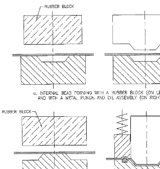
1-3-2-1 Beads and Ribs. There are two types of these formations: internal beads and external beads.
Internal Beads. It can be produced either by rubber pad forming, or by a set of match-ing dies.
forced into the die recess, the surrounding material is already restrained from movement by the pressure of the rubber pad. Therefore the only deforming portion is that of the bead itself, while the surrounding material is not influenced by the metal flow.
With die-forming of internal beads, the outward-protruding punch reaches the material first and starts to form the bead without establishing a firm restraining contact with the remaining material. The material under the punch is stretched and as the tool descends fur-ther, it pulls on the surrounding portions of material, possibly distorting it somewhat in the process, with dependence on the depth of the bead.
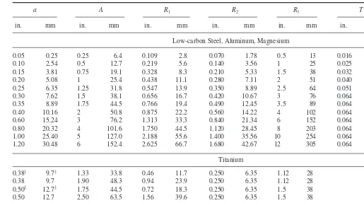
The maximum possible internal bead depth a(shown later in Figs. 1-34 and 1-35) depends primarily on the width of bead A, standard beads commonly having a ratio of width to depth between 4 and 6, or
(1-1)
On large, flat surfaces, beads should be spaced as closely as possible, to give maximum strength to the metal and to avoid large flat areas, which are inherently weak. Between parallel
A a=4 to 6
[image:30.540.39.358.66.403.2]28 CHAPTER ONE
beads, the minimum spacing is about 8ato allow full bead formation without fracturing the metal. Between a bead and a flange at right angle to the bead, allow 2a; between beads at right angles to each other, allow 3a; and between a bead and a flange parallel to the bead, allow 5a. External Beads. With external beads, the pressure of the rubber pad is first applied to the top of the bead (see Fig. 1-32b). Metal is locked at this point, and with increasing pressure the area between bead strips is stretched until it bottoms on the form block. Deformation being thus spread progressively over a large area, an external bead can be formed considerably deeper than an internal bead of the same curvature. Somewhat disadvantageous is the neces-sity of a rather large edge radius. Still, the contours of external beads are sharper than those of internal beads and for that reason the external beads are more efficient stiffeners of the two.
Of disadvantage is the wear and tear of the rubber tooling, which is considerable. This naturally drives the cost of any rubber-forming quite high.
Draw Beads. In forming or drawing process, a material-restraining action can be pro-vided by draw beads (Fig. 1-32c). These inserts not only secure the material in a given posi-tion, they further prevent its wrinkling during forming action.
The disadvantage of this application is the size of the draw radii. The draw radius of the punch should be four times the material thickness and the draw radius of the die still greater. If a smaller set of radii will be used, the material will tear. However, using greater than necessary radii will not aid the manufacturing process either. In such a case, the strip will not be restricted in its movement, and it may flow along with the forming or drawing action, resulting in the formation of wrinkles.
The only way to adapt the final corner radius to the requirements of the print or to those of practicality is to restrike that area of part after forming, with properly sized tooling.
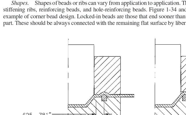
As shown in Fig. 1-33, there are two basic types of draw beads: mold-type draw beads and lock-type beads. Mold-type bead allows for some material movement in the area between the bead itself and the punch; the lock-type bead takes away that possibility.
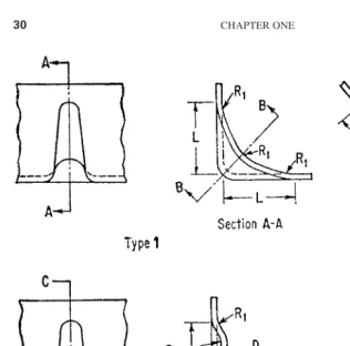
Shapes. Shapes of beads or ribs can vary from application to application. There are corner-stiffening ribs, reinforcing beads, and hole-reinforcing beads. Figure 1-34 and 1-35 show an example of corner bead design. Locked-in beads are those that end sooner than the edge of the part. These should be always connected with the remaining flat surface by liberal radii.
[image:31.540.37.361.377.578.2]BASIC DIE DESIGN AND DIE-WORK INFLUENCING FACTORS 29
30 CHAPTER ONE
[image:32.540.38.354.36.348.2]FIGURE 1-34 Corner bead design (Reprinted with permission from“Product Engineering Magazine.”)
A circumferential bulge (Fig. 1-36), a hem, a joggle, or a curl (Fig. 1-37), can all be con-sidered beads, for they provide the part with reinforcing action. A drawn-box can be rein-forced by making its sides slightly convex; a container can have a convex bottom or a recessed concave bottom not only to strengthen its construction but to flatten the circum-ferential area of its base as well.
The bead design data are given in Tables 1-1 and 1-2.
Reinforcing circumferential ribs (Fig. 1-36a) are usually formed around openings. Since the ribs are the last to be formed, with the hole already in place, they should be as far away from that opening as possible in order to minimize its distortion.
These beads are actually the size of their radius deep. The radius is dependent on the stock thickness, type of material, and forming pressure as follows:*
For circular ribs
(1-2a)
(1-2b)
and for elongated ribs
(1-3a)
(1-3b)
where R=bottom radius, in. or mm T=material thickness, in. or mm
S=tensile strength, lb/in.2or MPa (N⋅mm−2) P=forming pressure, lb/in.2or MPa (N⋅mm−2)
mm ( .
R TS P
= 6 894 10× −3) in
R =TSP
mm ( . )
( )
R = 6 894 10× −3 2TSP in
R =2(TSP )
BASIC DIE DESIGN AND DIE-WORK INFLUENCING FACTORS 31
*Formulas in this chapter are based on those given in Frank W. Wilson, Die Design Handbook, New York, 1965. Reprinted with permission from the McGraw-Hill companies.
TABLE 1-1 Corner Bead Design Data
In inches:
Spacing
Size M between
L Type R1 R2 R3 H (ref) beads
1/2 1 1/4 23/64 3/16 1/8 23/32 21/2 3/4 1 5/16 41/64 17/64 13/64 15/32 3
11/4 2 11/32 55/64 21/64 17/64 11/2 31/2
In millimeters:
12.7 1 6.4 9.1 4.8 3.2 18.3 63.5
19.1 1 7.9 16.3 6.7 5.2 29.4 76.2
31.8 2 8.7 21.8 8.3 6.7 38.1 88.9
Note: The chart refers to Fig. 1-34 .
32
a A R1 R2 R3 T* T†
in. mm in. mm in. mm in. mm in. mm in. mm in. mm
Low-carbon Steel, Aluminum, Magnesium
0.05 0.25 0.25 6.4 0.109 2.8 0.070 1.78 0.5 13 0.016 0.4 0.032 0.8
0.10 2.54 0.5 12.7 0.219 5.6 0.140 3.56 1 25 0.025 0.6 0.040 1.0
0.15 3.81 0.75 19.1 0.328 8.3 0.210 5.33 1.5 38 0.032 0.8 0.064 1.6
0.20 5.08 1 25.4 0.438 11.1 0.280 7.11 2 51 0.040 1 0.064 1.6
0.25 6.35 1.25 31.8 0.547 13.9 0.350 8.89 2.5 64 0.051 1.3 0.064 1.6
0.30 7.62 1.5 38.1 0.656 16.7 0.420 10.67 3 76 0.064 1.6 0.064 1.6
0.35 8.89 1.75 44.5 0.766 19.4 0.490 12.45 3.5 89 0.064 1.6 0.064 1.6
0.40 10.16 2 50.8 0.875 22.2 0.560 14.22 4 102 0.064 1.6 0.064 1.6
0.60 15.24 3 76.2 1.313 33.3 0.840 21.34 6 152 0.064 1.6 0.064 1.6
0.80 20.32 4 101.6 1.750 44.5 1.120 28.45 8 203 0.064 1.6 0.064 1.6
1.00 25.40 5 127.0 2.188 55.6 1.400 35.56 10 254 0.064 1.6 0.064 1.6
1.20 30.48 6 152.4 2.625 66.7 1.680 42.67 12 305 0.064 1.6 0.064 1.6
Titanium
0.38‡ 9.7‡ 1.33 33.8 0.46 11.7 0.250 6.35 1.12 28 3.88¶ 98.6¶
0.38 9.7 1.90 48.3 0.94 23.9 0.250 6.35 1.12 28
0.50‡ 12.7‡ 1.75 44.5 0.72 18.3 0.250 6.35 1.5 38 2.50¶ 63.5¶
0.50 12.7 2.50 63.5 1.56 39.6 0.250 6.35 1.5 38
0.70 17.8 3.50 88.9 2.32 58.9 0.250 6.35 2.0 51
0.88‡ 22.4‡ 3.08 78.2 1.46 37.1 0.250 6.35 2.52 64 1.76¶ 44.7¶
0.88 22.4 4.40 111.8 3.00 76.2 0.250 6.35 3.52 89
1.12‡ 28.4‡ 3.92 99.6 2.00 50.8 0.250 6.35 3.0 76 1.26¶ 32.0¶
1.12 28.4 5.60 142.2 3.82 97.0 0.250 6.35 3.0 76
*Maximum thickness for rubber-pad-formed beads on a hydraulic press. †Maximum thickness for beads formed by punch and die on a mechanical press.
‡Use when edge of bead to edge of sheet does not exceed the dimension shown.
¶Maximum distance between edge of bead and edge of sheet. See Fig. 1-35.
Note: Beads of these proportions may be formed in titanium pure AMS 4901, hot or cold. Further in titanium alloy RE-T-41 and in cold only RE-T-32. In the latter case, the radius
Copyright © 2004 The McGraw-Hill Companies. All rights reserved.
[image:34.540.70.585.36.323.2]1-3-2-2 Bosses or Buttons. These are flat-bottomed circular depressions or elevations in sheet (see Fig. 1-38). They are most often used for offsetting purposes, be it for hardware or for other applications. Their sizes and heights with respect to the given material thick-ness are listed in Table 1-3.
1-3-2-3 Flanges. These can be either straight or curved. Straight flanges are made by simple bending of a portion of sheet-metal material, with no flow of material involved in the process. Curved flanges seem to utilize simple bending technique as well; however, this is accompanied by stretching or compressing action on the material, which induces the material to flow. The material flow is similar to that in drawing or other cold work.
With curved flanges, there is always a certain amount of deformation involved. In convex or shrink flanges (Fig. 1-39b), the material of the flange is compressed in order to produce the required shape. In concave or stretched flanges (Fig. 1-39c), the material of the flange is elongated. The amount of deformation, when calculated, can be used to determine the exact type of the flange.
(1-4)
where R1is the edge radius before forming, in flat, in. or mm, and R2is the edge radius after forming, in. or mm.
% of deformation 100 2 1 1
= −
R R
BASIC DIE DESIGN AND DIE-WORK INFLUENCING FACTORS 33
[image:35.540.42.351.64.228.2]FIGURE 1-36 Circumferential ribs in stampings. (From Frank W. Wilson, “Die Design Handbook,” New York, 1965. Reprinted with permission from The McGraw-Hill Companies.)
If the deformation percentage comes out as a positive number, an elongation of mater-ial (stretch) is involved. With a negative number, the compression (shrink) is indicated. Table 1-4 gives maximum forming limits.
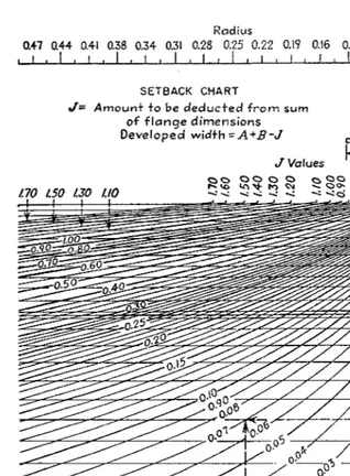
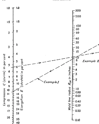
The amount of setback for all flanges can be determined from Fig. 1-40 by connecting the radius scale at the value Rto the thickness scale at the value of Twith a straight line. The setback value Jis read at the point where this line intersects the horizontal line repre-senting the bevel of the bend.
Flat-pattern flange width Ycan be calculated by using the following formula:
Y=W−J (1-5)
where Y=flange width, in flat, in. or mm W=formed flange width, in. or mm
J=value of setback, from Fig. 1-40
Dimensioning of stretch, shrink, and special flanges is given in Fig. 1-41. Dimensions for 90°flanges can be determined from Fig. 1-42, along with the percentage of elongation (stretch) or compression (shrink) in the metal of a given flange.
[image:36.540.74.321.51.228.2]34 CHAPTER ONE
TABLE 1-3 Design Data For Round Beads or Bosses
Height, h Material thickness
Suggested ratio,
in. mm in. mm H/h
1/16(.062) 1.59 .020 0.51 12–20
.031 0.79 14–24
.048 1.22 16–26
3/32 (.093) 2.38 .020 0.51 12
.031 0.79 14
.048 1.22 16
1/8 (.125) 3.18 .020 0.51 11
.031 0.79 12
.048 1.22 13
Note: Use with Fig. 1-38.
[image:36.540.77.316.442.573.2]Connect the flange width value Yto the amount of compression (shrink) with a straight line. Where this line crosses the mold line radius graph, that value is applicable to the given problem.
Dimensions for open or closed flanges can be determined from Fig. 1-43; the method for the chart’s use is similar to that described above.
The flange width Wor the projected flange width Hcan be determined from the lower scale. The approximate deformation of the free edge of curved flanges, percentagewise, is determined on the upper scale.
Permissible strain in stretched flanges depends on the edge condition of the metal, flange width (from Fig. 1-41), and method of forming. For 90°flanges, this value may be approximated by using the following formula
(1-6)
e W R
= 2
[image:37.540.45.356.63.209.2]BASIC DIE DESIGN AND DIE-WORK INFLUENCING FACTORS 35
TABLE 1-4 Maximum Forming Limits for Flanges
Stretch flanges Shrink flanges
(Elongation) (Compression)
Rubber Solid Rubber Solid
Material type tooling, % die, % tooling, % die, %
Aluminum 3003-O 20 30 5 40
Aluminum 3003-T 5 8 3 10
Aluminum 5052-O 20 25 5 35
Aluminum 5052-T 5 8 3 12
Aluminum 6061-O 21 22 8 35
Aluminum 6061-T 5 10 2 10
Aluminum 7075-O 10 18 3 30
Aluminum 7075-T 0 0 0 0
Steel 1010 – 38 – 10
[image:37.540.72.325.422.582.2]Steel 1020 – 22 – 10
where e=elongation (strain) factor at free edge of flange (see later) W= flange width, in. or mm
R2=contour radius of bent-up flange, in. or mm
Values for e. For 2024-0, -T3, and -T4 aluminum 90° flanges, 0.10 is a safe value for ewhere edges are smooth; 0.06 is a safe value for sheared edges. A larger degree of stretch
[image:38.540.41.359.62.494.2]36 CHAPTER ONE
occurs where contour radius R2is small or where the stretch flange is adjacent to a shrink flange.
Equation (1-6) for 90°stretch flanges also applies to 90°shrink flanges. Here, how-ever, the metal is in compression, and the sheet must be supported against “buckling” or “wrinkling.” With rubber forming, there is practically no support against buckling, and only slight shrinking can be accomplished, so that rubber forming is limited to very large flange radii or very narrow widths.
For 2024-0 aluminum, without subsequent rework, shrink is limited to not over 2 or 3 percent; for 2024-T3 and -T4, shrink is limited to 0.5 percent.
U.S. Air Force specifications indicate that there is danger of cracking when elongation exceeds 12 percent in 2 in. [50 mm]. Therefore, for safety, e=0.12, and
(1-7a)
For open flanges (i.e., angles smaller than 90°see Fig. 1-41) the formula is
(1-7b)
e W R
= (1−cos ) 2
α
R W R
2
2
0 88 −
= .
[image:39.540.37.359.60.332.2]BASIC DIE DESIGN AND DIE-WORK INFLUENCING FACTORS 37
Values of efor some other shaped flanges are as follows:
For flanges in Fig. 1-41c,
(1-7c)
e W R
= 1 2
[image:40.540.36.360.53.460.2]38 CHAPTER ONE
For flanges in Fig. 1-41d,
(1-7d)
For flanges in Fig. 1-41e,
(1-7e)
Cold forming changes the mechanical properties of carbon steel strip and produces cer-tain useful combinations of hardness, strength, stiffness, ductility, and other characteristics. Temper numbers indicate degrees of strength, hardness, and ductility produced in cold-rolled carbon steel strip. These temper numbers are associated with the ability of each tem-per to withstand certain degrees of cold forming.
The No. 1 temper is not suited for cold forming; temper Nos. 4 and 5 are used for pro-duction of parts that involve difficult forming or drawing operations.
1-3-2-4 Lightening Holes. These can be flanged in annealed aluminum alloys up to 0.125 in. [3.18 mm] thick and in heat-treated 2024 aluminum up to 0.064 in. [1.63 mm] thick.
Austenitic stainless steel up to 0.060 in. [1.52 mm] can be formed with external hole flanges and up to 0.050 in. [1.27 mm] thick with internal flanges. The quarter-hard stain-less steel up to 0.040 in. [1.02 mm] thick can be externally flanged, and internally flanged up to 0.030 in. [0.76 mm] thick.
Rubber-sheared lightening hole minimum diameters, in relation to aluminum alloy thicknesses, are shown in Table 1-5.
1-3-3 Forming Limitations
It is often difficult, with so many variables at stake, to guess what pitfalls the forming process will generate. Forming can turn a perfectly pierced, embossed, and blanked part into pitiful reject, eating into the company’s scrap allowance and diminishing profits. Where the edges of the part are almost invisibly splitting after blanking, large cracks and tears may emerge during forming. Heating of the part, or so-called torch annealing, may not always help. And generally advocated “laser it” approach may actually ruin the part altogether.
A laser-cut part has to put up with a molten stage around its edges, which is caused by the cutting process that depends on the speed of the tool and other variables. It will addi-tionally be disadvantaged by the difference in the material grain after cooling of the previ-ously heated areas and subsequent hardening of the surface of the cut and its immediate vicinity. Cracks and tears in the near proximity of laser cuts, especially where the laser “picked up” the path along the part’s edge, are often observed.
Lately, computerized simulating tools began to emerge. There were finite element analysis(FEA) packages developed for major three-dimensional (3D) solid modelers, with some FEA’s as standalones. Many of these are quite user friendly and some are remarkably fast for the amount of operations/calculations they must perform.
When evaluating a 3D analysis software, or perhaps any other software for that purpose, always try to have your own part, no matter how simple, modeled and analyzed right on the spot. This may help to ascertain the length of time and the amount of effort that particular software demands for an input of the information and for producing the results needed. Too many software packages nowadays can generate a so-called “movie,” which is a recording of the process, a sort of a “macro,” where only the changes on the screen are recorded and all the in-between mouse-clicks, “Enters,” keyboard hammering and frustrated hesitation, or waiting are weeded out.
e J R
= 2
e W W R
= 1+ 2 2 2
40 CHAPTER ONE
BASIC DIE DESIGN AND DIE-WORK INFLUENCING FACTORS 41
TABLE 1-5 Lightening Holes for 35°Flange∗
Flange height 0.125 in. (3.2 mm)
D H G T R
in. mm in. mm in. mm in. mm in. mm
0.445 11.30 0.812 20.62 1.223 31.06 0.020–0.040 0.51–1.02 0.187 4.75 0.400 10.16 1.212 30.78 0.051–0.072 1.30–1.83 0.250 6.35 0.570 14.48 0.938 23.83 1.348 34.24 0.020–0.040 0.51–1.02 0.187 4.75 0.525 13.34 1.337 33.96 0.051–0.072 1.30–1.83 0.250 6.35 0.695 17.65 1.062 26.97 1.473 37.41 0.020–0.040 0.51–1.02 0.187 4.75 0.650 16.51 1.462 37.13 0.051–0.072 1.30–1.83 0.250 6.35 0.820 20.83 1.188 30.18 1.598 40.59 0.020–0.040 0.51–1.02 0.187 4.75 0.775 19.69 1.587 40.31 0.051–0.072 1.30–1.83 0.250 6.35
Flange height 0.156 in. (4.0 mm)
0.900 22.86 1.312 33.32 1.800 45.72 0.020–0.040 0.51–1.02 0.187 4.75 0.852 21.64 1.791 45.49 0.051–0.072 1.30–1.83 0.250 6.35 1.150 29.21 1.562 39.67 2.050 52.07 0.020–0.040 0.51–1.02 0.187 4.75 1.082 27.48 2.041 51.84 0.051–0.072 1.30–1.83 0.250 6.35 1.276 32.41 1.688 42.88 2.175 55.25 0.020–0.040 0.51–1.02 0.187 4.75 1.208 30.68 2.166 55.02 0.051–0.072 1.30–1.83 0.250 6.35 1.400 35.56 1.812 46.02 2.300 58.42 0.020–0.040 0.51–1.02 0.187 4.75 1.332 33.83 2.294 58.27 0.051–0.072 1.30–1.83 0.250 6.35
Flange height 0.187 in. (4.7 mm)
1.606 40.79 2.062 52.37 2.625 66.68 0.020–0.040 0.51–1.02 0.187 4.75 1.543 39.19 2.617 66.47 0.051–0.072 1.30–1.83 0.250 6.35 1.490 37.85 2.611 66.32 0.081–0.102 2.06–2.59 0.312 7.92 1.856 47.14 2.875 73.03 0.020–0.040 0.51–1.02 0.187 4.75 1.793 45.54 2.312 58.72 2.867 72.82 0.051–0.072 1.30–1.83 0.250 6.35 1.740 44.20 2.861 72.67 0.081–0.102 2.06–2.59 0.312 7.92 1.982 50.34 3.000 76.20 0.020–0.040 0.51–1.02 0.187 4.75
Unfortunately, in die production, as well as in any other production, there may always be some parts that are not acceptable and which are going to be rejected. The only way to guard against large amounts of defective parts in the absence of a 3D analysis software is by testing every theory and every calculation out there, on the fac-tory floor. In fact, in critical areas, testing of formulas such as calculations of bend relieves, or the blank size development of a drawn shell, must definitely be performed using the material allotted to production of that part. Oftentimes, the tools to be used in production can be utilized for testing purposes while being groomed to size during the process.
These precautions are absolutely necessary in order to ensure that there will be no unknown or unpredictable variables affecting the results of the die operation in production and that rejects will not be streaming out of the press en masse.
[image:44.540.38.359.98.392.2]42 CHAPTER ONE
TABLE 1-5 Lightening Holes for 35°Flange (Continued)
Flange height 0.187 in. (4.7 mm)
D H G T R
in. mm in. mm in. mm in. mm in. mm
1.919 48.74 2.438 61.93 2.992 76.00 0.051–0.072 1.30–1.83 0.250 6.35 1.866 47.40 2.987 75.87 0.081–0.102 2.06–2.59 0.312 7.92 2.106 53.49 3.125 79.38 0.020–0.040 0.51–1.02 0.187 4.75 2.043 51.89 2.562 65.07 3.117 79.17 0.051–0.072 1.30–1.83 0.250 6.35 1.990 50.55 3.111 79.02 0.081–0.102 2.06–2.59 0.312 7.92 2.356 59.84 3.375 85.73 0.020–0.040 0.51–1.02 0.187 4.75 2.293 58.24 2.812 71.42 3.367 85.52 0.051–0.072 1.30–1.83 0.250 6.35 2.240 56.90 3.361 85.37 0.081–0.102 2.06–2.59 0.312 7.92 2.606 66.19 3.625 92.08 0.020–0.040 0.51–1.02 0.187 4.75 2.543 64.59 3.062 77.77 3.617 91.87 0.051–0.072 1.30–1.83 0.250 6.35 2.490 63.25 3.611 91.72 0.081–0.102 2.06–2.59 0.312 7.92 2.856 72.54 3.875 98.43 0.020–0.040 0.51–1.02 0.187 4.75 2.793 70.94 3.312 84.12 3.867 98.22 0.051–0.072 1.30–1.83 0.250 6.35 2.740 69.60 3.861 98.07 0.081–0.102 2.06–2.59 0.312 7.92 3.106 78.89 4.125 104.78 0.020–0.040 0.51–1.02 0.187 4.75 3.043 77.29 3.562 90.47 4.117 104.57 0.051–0.072 1.30–1.83 0.250 6.35 2.990 75.95 4.111 104.42 0.081–0.102 2.06–2.59 0.312 7.92 3.356 85.24 4.375 111.13 0.020–0.040 0.51–1.02 0.187 4.75 3.293 83.64 3.812 96.82 4.367 110.92 0.051–0.072 1.30–1.83 0.250 6.35 3.240 82.30 4.361 110.77 0.081–0.102 2.06–2.59 0.312 7.92 3.606 91.59 4.625 117.48 0.020–0.040 0.51–1.02 0.187 4.75 3.542 89.97 4.062 103.18 4.617 117.27 0.051–0.072 1.30–1.83 0.250 6.35 3.490 88.65 4.611 117.12 0.081–0.102 2.06–2.59 0.312 7.92 3.856 97.94 4.875 123.83 0.020–0.040 0.51–1.02 0.187 4.75 3.793 96.34 4.312 109.53 4.867 123.62 0.051–0.072 1.30–1.83 0.250 6.35 3.740 95.00 4.861 123.47 0.081–0.102 2.06–2.59 0.312 7.92
*These lightening holes may be formed in 5052-H32, 6061-T, 2024-T, 2014-T, R-301-T, and 7075-T aluminum alloy and AMC52SO and FS-Ia magnesium alloy or any softer condition of any of these alloys.
Some of these hard-to-predict outside influences, constraints, or enhancements include but are not limited to:
• Condition of the cutting, forming, or drawing surfaces
• Presence or absence of lubricants and their composition and suitability • Hardness of the material being fabricated
• Variation in thickness of sheet-metal material
• Clearance between the cutting, forming, and drawing punch and die • Spring pressure applied to the pad(s)
• Alignment between the segments of the die assembly • Ram force and speed
Most of these points are hardly accountable for in a majority of calculations. Actually, there is no way to implement them at all, for the situation will certainly change from one production run to another. For these reasons, the only safe way to proceed is to verify all applicable theo-retical results and assumptions out there on the factory floor while being aware of the possi-bility that one coil can have a different hardness or thickness than the other, watching for surprises created by spring breakage, and guarding the alignment of the die and that of the press.
1-3-4 Control of Close-Toleranced Dimensions
The control of dimensions in die work is still unequalled by other manufacturing processes. Already the fact that a fast-moving strip can be quickly and precisely positioned with the aid of pilots, stops, guides, and other locating elements just before the press comes down, speaks volumes about productivity and effectiveness. The possibility of staging various operations so that one does not affect the other, the wide range of operations that can be performed in a die, the versatility of this tooling approach are just few among many advan-tages the metal-stamping field presents.
For example, Fig. 1-44 shows a group of closely-spaced bopenings, serving as a start-ing point for some rather accurate dimensionstart-ing. The spacstart-ing between the groups would be jeopardized if a wrong sequence of die work were used. This is because such closely spaced piercing produces a distortion of the material structure, which results in its expansion in that particular area, often to the point of bulging above the remaining surface. This condition can be controlled to a degree with
• Specially shaped punches • Special cutting conditions • Staggered cutting
All these techniques are discussed in detail later. At this point, the sequence of opera-tions and their disbursement in a single progressive die will be discussed. Method No. 1 utilizes the following scenario:
1. Pierce the cluster of small bopenings by staggering the cuts as shown (two stations, each with a special cluster-punch needed)
2. Pilot on the two opposite holes, c1and c2for further strip advancement
3. Flatten the part in the die if needed or if advantageous
4. Pierce the two large holes, a1and a3, both sides
5. Pierce the middle large hole, a2, both sides
This sequence of operations should place the aholes into a reasonably exact distance off the center of the middle row of bholes.
If the punching was to be reversed and the large aholes were punched first, this by itself may have created enough stress-related movement within the material that the ±0.003 in. (0.08 mm) tolerance range will be out of question.
Flattening the part, even though recommended, cannot always be achieved. First of all, we do not know how much the part will bulge after such intense piercing, and therefore we often cannot produce such an arrangement to surely remedy the situation. After all, the results may vary from strip to strip with dependence on the hardness and the thickness of material.
Still another way to produce the hole pattern shown in Fig. 1-44 at a slightly greater cost is presented in the Method No. 2:
1. Pierce the cluster of small bopenings with a special cluster punch, all holes in one hit. However, the diametral size of each opening must be slightly smaller than that which is needed.
2. Pilot on the two opposite holes, c1and c2for further strip advance.
3. Pierce all three aholes (both sides), all of them smaller than they should be.
4. Repierce the cluster of bholes with the correct size punch and die.
5. Repierce the aholes (bot