1033 Advances in Materials and Processing Technologies II
Application of FEM in Investigating Machining Performance
Hendri Yanda
1, a, Jaharah A. Ghani
2, b, Che Hassan Che Haron
3, c1,2,3
Department of Mechanical and Materials Engineering,
Faculty of Engineering and Built Environment, Universiti Kebangsaan Malaysia, Bangi, Selangor Darul Ehsan, 43600 Malaysia
a [email protected], b [email protected], c [email protected]
Keywords: Finite element method, machining performance, rake angle, clearance angle.
Abstract. The two biggest problems that often experienced in machining cast iron are poor machinability and high hardness. Up to now, many researchers have investigated machining performance and how to find optimum condition in machining ductile cast iron. This study aims to investigate the machining performance of ductile cast iron and carbide cutting tool using FEM. Performances were evaluated by changing the cutting tool geometries on the machining responses of cutting force, stress, strain, and generated temperature on the workpiece. Deform-3D commercial finite element software was used in this study. Ductile cast iron FCD 500 grade was used as the work piece material and carbide insert DNMA432 type with WC (Tungsten) was used for the cutting tool. The effects of rake and clearance angles were investigated by designing various tool geometries. Various combination of carbide insert geometries were designed using Solid Work to produce +15, +20 and +30 deg for rake angle and 5, 7, 8 and 9 deg for clearance angle. Machining condition for the simulations were remained constant at cutting speed of 200 m/min, feed rate of 0.35 mm/rev, and depth of cut of 0.3 mm. The results of effective-stress, strain and generated temperature on both chip and material surface were analysed. The results show that by increasing the rake angle (α), it will improves the machining performance by reducing the cutting force, stress, strain and generated temperature on surface of workpiece. But, by increasing the clearance angle
(γ), it will not affect much to the cutting force, stress, strain and generated temperature on chip.
Introduction
Finite Element Analysis (FEA) technique was the first introduced in 1960s and still widely used for analysis such as in tools design and forming processes. Based on the success of FEM simulations for bulk forming processes, many researchers developed their own FEM codes to analyze metal cutting processes during the early 1980s up to now [1], [2], [3], [4] and [5]. Cerenitti et al. [1] assumed a rigid sharp tool and elasto-plastic workpiece, and defined a node separation criterion based on the geometry of the element approaching the cutting edge. Cerenitti et al. [1] used an early version of a commercial implicit FEM code “DEFORM-2DTM”. This code uses four-node quadrilateral elements and is based on static Lagrangian formulation. Today, DEFORM-3D™ code is commonly used by researchers and industry in machining simulation [6].
1034 Advances in Materials and Processing Technologies II
Methodology
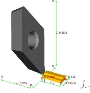
Orthogonal Cutting Condition Model. One of the important parameters in the orthogonal metal cutting process is the rake angle between the face of the cutting tool and the plane perpendicular to the cutting direction. The magnitudes of tool cutting geometries have significant effects on the performance of the cutting tool and the integrity of the cut surface. The main objective of this research is to apply the finite element method to study the rake angle and clearance effects in orthogonal metal cutting of ductile cast iron with continuous chip formation, while the other machining parameters of cutting speed, feed rate and depth of cut were kept constant. Finite element simulation results of the orthogonal metal cutting using three sets of perfectly sharp cutting tools with positive rake angles of 15, 20 and 30° and four clearance angles of 5, 7, 8 and 9 respectively. The commercial software Deform-3D for deformation analysis was used to simulate orthogonal metal cutting process. It is based on an updated Lagrangian formulation and employs an implicit integration scheme. Fig. 1 shows the schematic of orthogonal cutting condition model.
Parameter Inputs and Cutting Conditions. The three-dimensional finite element model was generated under a plane strain assumption because the width of cut was larger than the undeformed chip thickness in this orthogonal cutting arrangement. The flow stress behavior of the work material and the contact conditions were used as equation for flow stress σ models, σ = σ1εn [8]. Cutting conditions are predefined are shown in Table 1.
Table. 1: Parameter inputs in the simulation process Parameters
Cutting speed constant at 200 m/min
Feed rate constant at 0.35 mm/rev
Depth of cut (DOC) constant at 0.3 mm
Rake angle (α), deg 15 20 30
clearance angle (β), deg 5 7 8 9 5 7 8 9 5 7 8 9
The workpiece material was ductile cast iron FCD500 grade. This material was selected as the workpiece material in this study because it was widely used in automotive application. Deform-3D software was used to simulate the effect of tool cutting geometries in turning ductile cast iron using uncoated carbide cutting tool. The simulations were performed by changing the rake angle and clearance angle while the cutting speed, feed rate and depth of cut were kept constant at 200 m/min, 0.35 mm/rev and 0.3 mm respectively. The simulation results of cutting force, effective-stress, strain and generated temperature on the workpiece surface were studied and analyzed. The operation is simulated using insert carbide of DNMA432 type that has a nose angle of 55 deg and without the use of coolant. The tool was defined to be a rigid body which considers thermal transfer
1035 Advances in Materials and Processing Technologies II
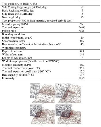
for modeling the cutting temperature field. Cutting condition, simulation models and material properties of carbide cutting tool and workpiece are shown in Table 2.
Table 2: Cutting condition to the simulation models and material properties
Displacement, shape and surface mesh of the tool and workpiece at the initial mesh of beginning the cutting operation was developed until chip formation reach step 100 as illustrated in Fig. 2a , 2b, 2c and 2d respectively. The workpiece and the tool are characteristized by non uniform mesh distribution in the simulation. Very small element is required in the contact area between tool and workpiece because of very large temperature gradient and stress that will develop in this region during the simulation.
Design of Cutting Tool Geometries. Cutting tools were designed for various rake angles of +15, +20 and +30 deg and the clearance angles of 5, 7, 8 and 9 deg. There are twelve combinations of geometry designs for carbide tool using Solid Work software as shown in Fig 3.
Tool geometry of DNMA 432
Side Cutting Edge Angle (SCEA), deg -3
Back Rack angle (BR), deg -5
Side Rack angle (SR), deg -5
Nose angle, deg 55
Tool properties (WC as base material, uncoated carbide tool)
Modulus young (GPa) 650
Heat transfer coefficient at the interface, N/s mmoC 45 Workpiece geometry
1036 Advances in Materials and Processing Technologies II
Simulation Results and Discussion
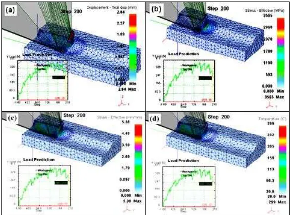
Primary and Secondary Deformation Zone. Fig. 4 shows the simulation results for displacement, cutting force, effective stress, strain and generated temperature for rake angle of +20 deg and clearance angle of 5 deg (cutting speed of 200 m/min, feed rate of 0.35 mm/rev and DOC of 3 mm) The biggest displacement was reached around 2.84 mm in total displacement at the end of chip formation (Fig. 4a). The biggest deformation was occurred on the primary deformation zone, followed by the secondary deformation zone. This also causes higher stress occurred on this area, about 3565 MPa in primary shear zone (Fig.4b). These results are agreeable with Kalhori [9], where the major deformation during cutting process were concentrated in two region close to the cutting tool edge, and the bigger deformation were occurred in the primary deformation zone, followed by secondary deformation zone, sliding region and sticking region.
Fig. 4 Simulation results for cutting speed of 200 m/min, rake angle of +20 deg and clearance angle of 5 deg), a) Displacement, b) Effective
stress, c) Effective Strain and c) Generated temperature.
1037 Advances in Materials and Processing Technologies II
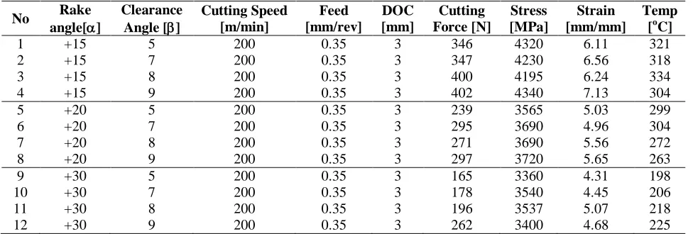
Fig. 4c shows the highest effective strain occurred on primary shear zone about 5.03 mm/mm, and then followed by secondary shear zone about less than 2.69 mm/mm. And, the highest temperature was occurred at sliding region on primary shear zone around 299 oC as shown in Fig 4d. Table 3 shows the simulation results for all various rake and clearance angle where cutting speed, feed rate and depth of cut (DOC) that were kept constant at 200 m/min, 0.35 mm/rev and 3 mm respectively.
Table 3: The result of simulation for cutting force, stress, strain, and temperature
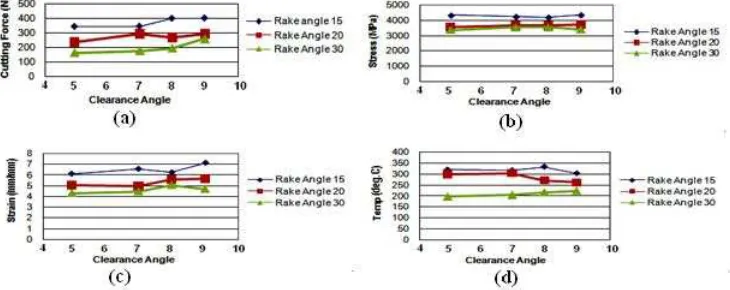
No Rake strain and generated temperature are decreasing as shown in Fig. 5a, 5b, 5c and 5d respectively. For example, increasing the rake angle from +15 deg to +20 deg, will reduce the cutting force from 346 N to 239 N, stress from 4320 MPa to 3565 MPa, strain from 6.11 to 5.03 mm/mm and temperature from 321 oC to 299 oC. This can be accepted that the reducing in cutting force, stress, strain and temperature were resulted from reduction of tool/chip contact area, so the cutting force and friction are expected to be decreased. This is agreeable with theory and experiment done by Gunay et al [10].
The Effect of Clearance Angle (γ). The increase of clearance angle does not much influence the cutting force, stress, strain and generated temperature as shown in Fig. 6a, 6b, 6c, and 6d. All of these results were also agreeable with the theory, because the change of clearance angle will not affect the cutting force and stress, but the increase of clearance angle only affects slightly on the wear rate. Clearance angle will affect wear and tool life of the cutting tool because the clearance
Fig. 5 Effect of rake angle, (a). rake angle vs cutting force, (b). rake angle vs stress, (c). rake angle vs strain, and (d). rake angle vs
1038 Advances in Materials and Processing Technologies II
face will rub against the freshly cut metal surface. In industry, the clearance angle is varied, but often in the order of 6 – 10 deg [11].
Conclusion
The distribution of cutting force, effective stress and generated temperature obtained from simulations are agreeable with the results given in literature. From the simulation, it can be
concluded that increasing the rake angle (α) in the turning of ductile cast iron using tungsten carbide (CW), it will improves the machining performance by reducing the cutting force, stress, strain and generated temperature. But, by increasing the clearance angle (γ), it will not influence much to the cutting force, stress, strain and generated temperature on chip.
References
[1] T.D. Marusich and Ortiz: Modeling and Simulation of High-Speed Machining, To appear: International Jour. Num. Metallurgy Engineering. (1995).
[2] A. E. Cerenitti, B.P. Fallbohmer, W. Wu C.W and Altan B.T: Application of 2D FEM to Chip Formation in Orthogonal Cutting, Jour. of materials Processing Technology Vol. 59
(1996), p.169-180.
[3] J. Q. Xie, A. E. Bayoumi, and H. M. Zbib: FEA Modelling and Simulation of Shear Localized Chip Formation in Metal Cutting, Jour. of Materials Processing Technology Vol. 38
(1998), p.1067-1087.
[4] C. Shet: Finite Element Analysis of the Orthogonal Metal Cutting Process, Jour. of Materials Processing Technology Vol. 105 (2000), p. 95-109
[5] A.E.Cerenitti, C.Lazzaroni, L.Menegardo and B.T.Altan: Turning Simulation Using a Three- Dimensional FEM Code, Jour. of materials Processing Technology Vol. 98 (2000), p.99-103. [6] O.H.Columbus, in : DeformTM - 3D Machining (Turning) Lab, Scientific Forming Tech.
Corporation (2007).
[7] J. Mackerle: Finite Element Analysis and Simulation of Machining: a Bibliography (1976 – 1996), Jour. of Materials Processing Technology Volume 86 (1999), p. 17-44.
[8] P. L. B. Oxley, in: Mechanics of Machining: An Analytical Approach to Assessing
Machinability, Ellis Horwood, Chichester, West Sussex (1989), p. 223–227
[9] V. Kalhori, in: Modelling and Simulation of Mechanical Cutting, Doctoral Thesis,
Institutionen for Maskinteknik, Sweden (2001).
[10] M. G. Gunay, I. Korkut, E. Aslan and U. S. Eker: Experimental investigation of the effect of cutting tool rake angle on main cutting force, Jour. of Materials Processing Technology Vol. 166 (2005), p. 44–49.
[11] E. M. Trent, in: Metal Cutting, Butterworth - Heinmann Ltd, London (1991). Fig. 6 Effect of clearance angle, (a) clearance angle vs cutting Speed, (b) clearance
1033 Advances in Materials and Processing Technologies II
Adv a n ce d M a t e r ia ls Re se a r ch ( V olu m e s 2 6 4 - 2 6 5 )
Alamat web: http://www.scientific.net/AMR.264-265.1033
1034 Advances in Materials and Processing Technologies II
Ed itors
Hu , X.Z.
The Universit y of Western Aust ralia, School of Mechanical and Chem ical Engineering; Applied Mechanics & Advanced Materials Group, Pert h, Aust ralia, WA 6009;
Lau , A.K.T. Send m ail
Hong Kong Polytechnic Universit y, Departm ent of Mechanical Engineering; Hung Hom , Kow loon, Hong Kong, China;
Publishing Edit or Wohlbier , T. Send m ail
105 Springdale Lane, Millersville, United St at es of Am erica, PA 17551; Ed itor ia l Boa rd
Bart on , J. Send m ail
Universit y of Sout ham pt on, School of Engineering Sciences; Highfield, Sout ham pt on, United Kingdom , SO17 1BJ;
Cao , P. Send m ail
Universit y of Waikat o, Departm ent of Mat erials and Process Engineering, Waikat o Cent re for Advanced Mat erials; Privat e Bag 3105, Ham ilt on, New Zealand, 3240;
Chandra , T. Send m ail
Universit y of Wollongong, Facult y of Engineering, School of Mechanicals, Mat erials and Mechat ronic Engineering; 33 Boot ie St reet, Wollongong, Aust ralia, NSW 2522;
Chicinaş , I. Send m ail
Technical Universit y of Cluj - Napoca, Departm ent of Mat erials Science and Technology; 103- 105 Muncii Blv., Cluj - Napoca, 400641, Rom ania;
Daniel , B.S.S. Send m ail
I ndian I nst it ute of Technology Roorkee, Departm ent of Metallurgical and Materials Engineering, Cent re of Nanotechnology; Roorkee, I ndia, 247 667;
Engel , U. Send m ail
Friedrich- Alexander- Universit ät Erlangen- Nürnberg, Chair of Manufact uring Technology; Egerlandst rasse 11- 13, Erlangen, 91058, Germ any;
Evans , S.L. Send m ail
Cardiff Universit y, Cardiff School of Engineering; Queen's Buildings, P.O.Box 925 Parade, Newport Road, Cardiff, United Kingdom , CF24 3AA;
Gao , H. Send m ail
Dalian Universit y of Technology, School of Mechanical Engineering; Dalian, Liaoning, China, 116024;
I bhadode , A.O.A. Send m ail
1035 Advances in Materials and Processing Technologies II
Jha , P.K. Send m ail
Bhavnagar Universit y, Departm ent of Physics; Bhavnagar, I ndia, 364001;
Kim , J.K. Send m ail
Hong Kong Universit y of Science and Technology, Departm ent of Mechanical Engineering; Clear Wat er Bay, Pokfulam Road Kow loon, Hong Kong, China;
Leng , J.S. Send m ail
Harbin I nst it ute of Technology, Center for Com posite Materials and St ruct ures; BLDG. A, Science Park of Harbin I nst it ut e of Technology, No. 2 Yikuang St reet Nangang DI ST., Harbin, Heilongj iang, China, 150080;
Palkowski , H. Send m ail
Claust hal Universit y of Technology, I nst it ute of Met allurgy; Robert - Koch-St rasse 42, Claust hal- Zellerfeld, 38678, Germ any;
Pullin , R. Send m ail
Cardiff Universit y, Cardiff School of Engineering; Queen's Buildings, P.O.Box 925 Parade, Newport Road, Cardiff, United Kingdom , CF24 3AA;
Sand , W. Send m ail
Universit y of Duisburg- Essen, Biofilm Cent re, Aquat ic Biot echnology; Geibelst rasse 41, Duisburg, 47057, Germ any;
Schikorra , M. Send m ail
Technical Universit y of Dortm und, I nst itut e of Form ing Technology and Light weight Const ruct ion ( I UL); Baroper St reet 301, Dort m und, 44227, Germ any;
Yin , Y.S. Send m ail
Shanghai Marit im e Universit y, I nst itute of Marine Materials Science and Engineering; 1550 Harbor Ave, Lingang New Cit y, Shanghai, China, 200135;
Zhang , D.L. Send m ail
Universit y of Waikat o, Waikat o Cent re for Advanced Materials (WaiCAM) , School of Engineering; Private Bag 3105, Ham ilt on, New Zealand, 3240;
Zhang , T.Y. Send m ail
1033 Advances in Materials and Processing Technologies II
DAFTAR ISI