POINT CLOUDS TO INDOOR/OUTDOOR ACCESSIBILITY DIAGNOSIS
J. Balado a, *, L. Díaz-Vilariño a,b, P. Arias a, I. Garridoa
aApplied Geotechnologies Group, Dept. Natural Resources and Environmental Engineering, University of Vigo, Campus
Lagoas-Marcosende, CP 36310 Vigo, Spain – (jbalado, lucia, parias, ivgarrido)@uvigo.es
bGIS Technology, OTB Research Institute for the Built Environment, Julianalaan 134, 2628 BL Delft, The Netherlands -
Commission IV, WG IV/5
KEY WORDS: Building accessibility, Indoor/Outdoor seamless modelling, indoor/outdoor mobility, 3D reconstruction, Building Information Modelling.
ABSTRACT:
This work presents an approach to automatically detect structural floor elements such as steps or ramps in the immediate environment of buildings, elements that may affect the accessibility to buildings. The methodology is based on Mobile Laser Scanner (MLS) point cloud and trajectory information. First, the street is segmented in stretches along the trajectory of the MLS to work in regular spaces. Next, the lower region of each stretch (the ground zone) is selected as the ROI and normal, curvature and tilt are calculated for each point. With this information, points in the ROI are classified in horizontal, inclined or vertical. Points are refined and grouped in structural elements using raster process and connected components in different phases for each type of previously classified points. At last, the trajectory data is used to distinguish between road and sidewalks. Adjacency information is used to classify structural elements in steps, ramps, curbs and curb-ramps. The methodology is tested in a real case study, consisting of 100 m of an urban street. Ground elements are correctly classified in an acceptable computation time. Steps and ramps also are exported to GIS software to enrich building models from Open Street Map with information about accessible/inaccessible entrances and their locations.
1. INTRODUCTION
3D models are becoming essential to represent cities and the basis for storing and using the information of the as-built environment. Streets can be rapidly depicted with a high level of detail with Mobile Laser Scanner systems (Puente et al., 2012), providing a large amount of unstructured data in the form of point clouds. Reconstruction from point clouds is still a challenging research topic since different applications are increasingly requiring more realistic and more detailed models. Path planning is one example of an application requiring a high level of detail. An in-depth knowledge of floor elements is essential to diagnose the accessibility to public spaces, especially in the case of people with reduced mobility (PRM) and people with disabilities that have different motor skills (Hashemi and Karimi, 2010) since a small step may become a barrier to access to a specific location. Accessibility diagnosis from point clouds has been mostly studied, from an indoor or from an outdoor perspective, as stair or curb detection. In outdoors, Serna and Marcotegui (2013) combine raster images with mathematical morphology to complete occlusions in point clouds and detect curbs and their absence (considering curb-ramps). From airborne point clouds, Vosselman and Liang (2009) analyse small height jumps close to ground to detect curbs and they extract separately with connected components. Rodríguez-Cuenca et al. (2015) support curb detection with the use of MLS trajectory, working in perpendicular sections to trajectory direction. Modelling entire regions and detecting stairs in them is another way of accessibility analysis (Sanchez and Zakhor, 2012). Schnabel et al. (2008) use topology graphs of complex elements, as stairs and columns, to detect their features in a scene. The robotics community also has an interest in accessibility analysis. Mobile robots based on legs (Luo et al., 2013; Oßwald et al., 2011) or wheels (Riascos, 2015; Zhang et al., 2011) should perceive and understand their immediate environment to be able to move
* Corresponding author
through them, detecting and climbing curbs and stairs. Unlike methodologies based on large point clouds, robots focus on the acquisition and processing in small zones near them, without difference between indoor and outdoor environments. Accessibility in indoors is analysed from the creation of a buffer in Díaz-Vilariño et al. (2016). The buffer, a 3D prism representing a person, is used to detect obstacles along indoor paths. Its size can be adapted to simulate PRM conditions. Transition areas between indoors and outdoors such as building entrances along façade lines are of special relevance for ensuring a seamless path planning in public spaces. Entrances are mainly approximated by doors in detection and modelling. The limitation of this method lies in the fact that when a door does not exist or it is occluded, any entrance is detected in the building. Many authors model doors as façade elements, joined with windows or balconies (Friedman and Stamos, 2011; Nguatem et al., 2014; Pu and Vosselman, 2009). Schmittwilken and Plümer (2010) reconstruct parts of facades, including doors and stairs. Their methodology pre-filters the TLS point cloud, working with less point density. Next they extract features and locations of small façade elements and, with a decision tree supported by a scored function, they predict element type. Stairs are estimated as a combination of treads and risers. In indoor scenes, doors and their gaps are detected, but not analysed regarding their accessibility, mainly because doors do not usually present any steps or physical barrier to PRM in indoors scenes. Díaz-Vilariño et al. (2015) model indoor spaces and detect closed doors from imagery and point cloud. By contrast, Quintana et al. (2016) focus indoor door detection in empty voxels in walls on detecting doors and Ochmann et al. (2014) use overlapping between different scan positions to detect door gaps.
The aim of this work is to analyse accessibility of building entrances and their immediate environment from MLS street point clouds, automatically detecting steps, ramps, curbs, and curb-ramps. The proposed methodology employs trajectory as ISPRS Annals of the Photogrammetry, Remote Sensing and Spatial Information Sciences, Volume IV-2/W4, 2017
semantic information and to save computing time in the segmentation process. Topology information is applied to improve classification quality of final results and to not only depend on geometric information. Stairs are considered as a group of steps, and the step detection is based on the vertical components (risers), that present better point density than the horizontal elements (treads) and they are the real architectonic obstacle for PRM. Ramps and steps usually are associated to entrances to shops, dwellings or basic services, so it is not necessary any methodology based on door detection. Elements detected can be georeferenced exported to enrich models reconstructed with other methodologies.
2. METHODOLOGY
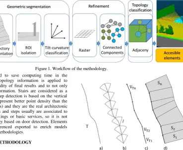
The methodology starts by analysing the geometry of the point cloud. First, the street point cloud is segmented in regular stretches and a ROI is selected to focus future calculus only in this zone, saving computer time and resources. Next, points in the ROI are classified in horizontal, inclined and vertical points using normal and curvature to refine them separately. In the refinement process, raster and connected components are used to filter and group points to detect the preliminary floor elements that are topologically classified in the last phase. Figure 1 shows the general workflow of the methodology.
2.1 Geometric segmentation
2.1.1 Trajectory segmentation: Trajectory data is a set of points geo-located along the trajectory of the vehicle registered during the acquisition. It has a smaller size than the point cloud, so processing trajectory data is faster than processing the street point cloud with the same operations. The trajectory information is used in this work to segment street point cloud in regular stretches. The set of points of the trajectory T = XT, YT, ZT (Figure 2.a) is segmented in regular intervals searching neighbours within a distance l = 1 meter (Figure 2.b). The set of points is transformed into vectors VT= V , V , V , with
‖VT‖ ≈ � and let VTi= Ti i� + − Ti i� (Figure 2.c). At this moment, street point cloud P = X , Y , Z is loaded and segmented in stretches S = {S , S … S } perpendicular of each vector at the final point Si= {P:<⊥ Ti i� + } (Figure 2.d).
2.1.2 ROI isolation: The region of interest CR i⊂ Si is the ground zone corresponding with the lowest d = 0.5 meters of each stretch, this points of the ROI are selected using M-estimator SAmple Consensus (MSAC) (Torr and Zisserman, 2000) and oriented according to the ground vector to compensate the trajectory tilt (Figure 3). The ground vectors are calculated as the cross product V = VT× V, being the façade vectors perpendicular to trajectory vectors with null V, V =
−V , V , .
2.1.3 Classification: A bidirectional classification is needed to differentiate the tilt in the trajectory direction VT and the perpendicular tilt to the trajectory directionꓕVT. The curvature associated with each point in relation to neighbour points also is used in the classification process. Tilts are calculated with the normals N = (NV
T, NꓕVT, N ) referenced to the trajectory
direction (Eq. 1-3). The number of neighbours to estimate normals is established at k = 50 points with KNN search, a balance of run-time and point cloud noise. The curvature Nvaris calculated as the mean of normal variance components of the k nearest points (Eq. 4).
tiltVT= abs atang
NVT
N (1)
tiltꓕVT= abs atang
NꓕVT
N (2)
tg= abs atang
√V + V
V (3)
Figure 1. Workflow of the methodology.
Figure 2. Trajectory segmentation: a) point line of MLS trajectory, b) radius search along trajectory, c) stretch vectors,
d) point cloud in stretches.
Figure 3. Ground vector calculation in stretches and ROI selection.
Nvar= ∑ Ni− N̅̅̅i i=
(4)
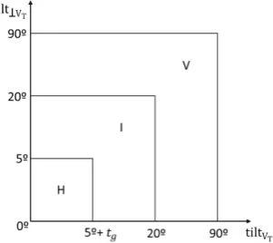
There are three thresholds in the bidirectional tilt classification (Figure 4). The 5º threshold is used to filter noise, and to correct small gradients and deformations in the ground because the floor is not completely horizontal and plane. In the trajectory direction, the threshold is compensated with ground tilt � in order not to consider all inclined floors in streets as ramps. The 20º threshold is based on ISO-21542 (ISO, 2011) that sets the max tilt in passable surfaces on 15º (5º degrees more provide robustness to the classification method). Finally, the 90º threshold limits vertical surfaces.
Figure 4. Bidirectional thresholds in the classification of points with an associated tilt horizontal-H, inclined-I and vertical-V.
The abovementioned thresholds produce good results except in the union between horizontal and vertical regions (difference in Figure 5). Tilts and normals do not change abruptly; the k neighbours used in the normal estimation produce a gradual change and wrong classified points with intermediate inclined tilts (blue vectors in Figure 5.a). To solve this, the points associated with an inclined tilt and high curvature c (experimentally set in c≥ 0.01) are saved in a temporal dataset to classify them as floor elements in future phases.
Figure 5. Normal estimation in a vertical (a) and inclined (b) element. In green, vector associated to vertical points; in blue,
inclined; and in yellow, horizontal.
2.2 Refinement
2.2.1 Horizontal regions: The points H with a horizontal associated tilt are refined in each stretch using connected components. It is a technique commonly used in image processing (Bieniek and Moga, 2000; Di Stefano and Bulgarelli, 1999; Samet, 1981) and recently in 3D point cloud processing (Trevor et al., 2013). First, the adjacency relations between points are calculated within a distancer = 5cm (Figure 6.b). Points and their adjacency relations are ordered in graphs and connected components are applied to group points in regions (Figure 6.c). The regions with less than np = 50 points are considered as noise and they are deleted. At last, points with an inclined tilt and high curvature, saved in the temporal dataset in the previous phase, are joined to the nearest group.
Figure 6. Connected components for horizontal regions: a) points with horizontal tilt, b) adjacency relation between points,
c) points grouped.
2.2.2 Inclined regions: The points I with an inclined associated tilt and low curvature are joined from all stretches. The adjacency is calculated and connected components is applied to group them. In difference with horizontal regions, inclined regions are filtered by a minimum size. The minimum size is 80cm (ISO-21542), called free passage surface, because it ensures enough space for crossing it comfortably by a person.
2.2.3 Vertical regions: The points W with a vertical associated tilt are refined in two phases: a raster process followed by connected components. First, stretch by stretch, points are rotated R and adjusted to a grid (resolution of 10cm) along the trajectory direction (Eq. 5-6) and rasterised (Figure 7). Then, the pixels with a height jump between 5cm (measure defined by scan resolution) and 20cm (measure based on max step height in built environment) are detected at less than dg = 30cm distance to the ground to prevent false positives.
αi= atan Vi⁄−Vi (5)
Hi= WiRi= Wi[
cos αi −sin αi
sin αi cos αi ] (6)
Figure 7. Point adjustment to raster grid: a) points and trajectory vector, b) points in the raster grid without adjustment, c) points
rotated in the raster grid.
The points belonging to the selected pixels are extracted and joined by the same type of points in the others stretches. Connected components are now applied, with the same aim and parameters as the inclined points.
2.3 Topology classification
In this phase, relations between regions are analysed. Horizontal regions R can be roads or sidewalks; inclined R can be ramps or curb-ramps and vertical RVcan be steps or curbs. First, in each stretch, the road region is detected as the nearest region to the trajectory data Rr adi= R i:min|R i− Ti| and the other regions are classified as sidewalks. The classified R are now joined from all the stretches. Finally, the relations of inclined and vertical regions with roads and sidewalks are processed to label each region with the correct element (Figure 8).
Figure 8. Adjacency relations between floor elements and the trajectory.
If a vertical region has adjacency with a road, it is a curb, else it is a step. If an inclined region has adjacency with a road and a sidewalk, this region is a curb-ramp, if only has adjacency with a sidewalk, it is a ramp; and if it only has adjacency with a road, this region is a camber and points that formed it are joined to the corresponding road region.
3. EXPERIMENTS
3.1 Results
The methodology was tested in a real case study with 12.7 million points in 125 meters of Florida Avenue, in Vigo, Spain (Figure 9). It is an urban street with shops, dwellings and garage entrances. It was acquired using MLS LYNX Mobile Mapper of Optech (Puente et al., 2013). The code was run on an Intel Core i7 CPU 3.40 GHz with 16GB RAM using MATLAB. The time processing was 535 seconds (about 9 minutes), an acceptable computing time in processing large zones in urban environments. The results are quantified as the number of points correctly classified using precision, recall and F1 indices (Vo et al., 2015), they are calculated with Eq. 7 to 9. The automatically processed point cloud is compared with a reference hand-made classified point cloud in steps, curbs, ramps and curb-ramps. True positive
points (TP) are those that pertains to the same element in both point clouds. False positive (FP) points are wrongly classified as a specific element when in the reference point cloud they pertain to another element. False negatives points (FN) are wrongly not classified as a specific element when in the reference point cloud they belong to it. The results of the quantitative evaluation of the dataset are shown in Table 1 and Figure 10, with the threshold values exposed in the methodology (Section 2).
��� � =|TP| + |FP||TP| (7)
����� =|TP| + |FN||TP| (8)
� = x ��� � + �������� � x ����� (9)
3.2 Discussion
Steps were correctly detected with a 92.75% of success rate (Figures 10.a,b,d,e,f). All steps in building entrances are correctly detected if their height is in the threshold explained in Section 2.2.3. There are not false positives caused by objects on sidewalks, as pedestrians, trees or containers; false positive points correspond to objects placed into building entrances and buildings and in shop windows with a similar geometry than a step.
Ramps are correctly detected in a 75.83%, being the lowest success rate of all classified elements (Figure 10.c). In the dataset, there are a lot of tree gratings (Figures 10.f,g). They are horizontal elements composed by curved elements with inclined normals. The normals are used in the methodology to classify points into horizontal/inclined regions as groups of points with horizontal/inclined normals. As they have similar size than an entrance ramp, connected components do not filter tree gratings and leave them as ramps. The rest of ramps in entrances are correctly classified. The recall index, by contrast, has a more elevated value, near to global results. All ramps in entrances are correctly detected, even in anomalous situations (Figures 10.b,d), when a ramp is built united with a step, ramps were correctly detected.
Curbs have the highest success rate among all classes: 98.66%. Their proximity to the laser scanner and the lack of occlusions produce their classification correctly (Figures 10.e-g). Only small fragments with greater height than the established thresholds are not detected (Figure 10.e).
Table 1. Results.
TP FP FN precision Recall F1
steps 28114 3011 1385 90,33% 95,30% 92,75%
ramps 11486 6528 796 63,76% 93,52% 75,83%
curbs 99747 947 1772 99,06% 98,25% 98,66%
curb-ramps 33740 4674 4896 87,83% 87,33% 87,58%
Figure 9. Florida Avenue point cloud.
There are two curb-ramps in the tested dataset, both are associated to garage entrances and not pedestrian crossings. The 87.58% of their points were correctly detected (Figure 10.g). The false positive points are in zones near sewers and sidewalks with an elevated camber. The rest of camber regions are correctly classified as road in topology classification. The false negative points are near true curb-ramps, they were not detected because of local deformations.
The variation of the thresholds influences final success rates. The classification thresholds (Section 2.1.3.) are especially relevant in final results and they are analysed in order to maximize the F1 index. Figures 11 to 13 show the F1 variation with different values of k, tilt and c, respectively. The rest of parameters are fixed in k = 50 neighbours, tilt = 5º to 20º and c = 0.001, values for the optimum results (Table 1).
The methodology has high success rates, and errors are uncommon and are located in specific zones. The results are good even in zones out of classic distributions of urban ground and building entrances: uncommon combinations of ramps with steps. The processing time is acceptable to classify one side of the street.
Modifying the size and the position of the ROI, the search can be focused on specific elements: curbs and curb-ramps selecting the zone near trajectory as the ROI, or ramps and steps selecting the
zone near façades. A smaller size of the ROI involves the diminution of time processing.
The methodology offers a robust solution against small occlusions caused by pedestrians, trees or pole-likes. In contrast, if the acquisition is carried out from a MLS mounted on a van and there are cars parked on the street, the point cloud could be very occluded and incomplete. In this case, the laser scanner must be installed in another mobile solution to acquire the point cloud with enough quality in terms of completeness.
3.3 Model enrichment
Many times it is not necessary to model a complete zone, on the internet there are databases where cities are modelled in a low level of detail. Open Street Map, for example, is a project to create free maps by users manually, but not automatically. People can map elements and zones using orthoimages, where streets and roofs are clearly visible. Although entrances are considered, they are not usually represented because they are difficult to detect in the orthoimages. Therefore, users can only mark the entrances if they already know their approximate location.
Figure 11. Relation between F1 index and k value
Figure 10. Results. Colour code: steps in orange, ramps in blue, curbs in green, curb-ramps in violet, sidewalks in olive, road in
grey and the rest of elements in dark green.
Figure 12. Relation between F1 index and bidirectional tilt ranges
Figure 13. Relation between F1 index and c value Figure 11. Relation between F1 index and k value ISPRS Annals of the Photogrammetry, Remote Sensing and Spatial Information Sciences, Volume IV-2/W4, 2017
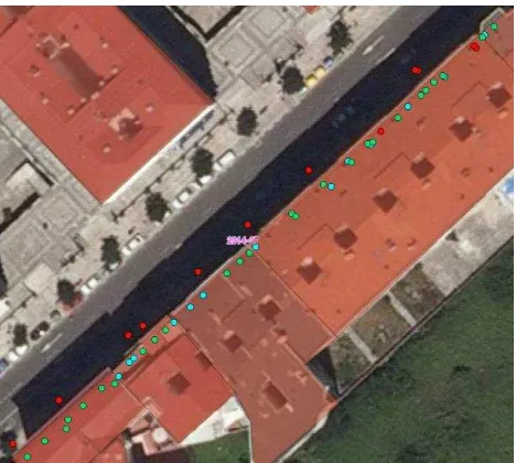
In this work, the floor elements detected with the proposed methodology are georeferenced (MLS provides georeferenced point cloud). Therefore, ramps and steps detected are exported as georeferenced points (middle point of each element) and, from Open Street Map, building polygons from the Florida Avenue were extracted to QGIS. Combining the two layers in the same Coordinate Reference System and applying the vector operation of intersecting, entrance steps and ramps are associated to the building polygons (Figure 14). Out of building polygons, false positives caused by tree gratings can be separated.
Figure 14. Location of step and ramp entrances. Colour code: buildings in semi-transparent red, step entrances in green, ramp
entrances in blue and tree gratings and entrance errors in red.
4. CONCLUSSION
This paper presents an automatic methodology for accessibility analysis in building entrances and their immediate environment. It is based on step and ramp detection without requiring a previous phase of door or gap detection. As the methodology is applied to small stretches of the street, it is scalable to large zones.
The methodology was tested on a real dataset, 125 meters of a street. The computing time was 9 minutes, an acceptable time to process urban zones. The results show a success rate of 75.9% to 98.7%, depending on the type of element, working even with a complex combination of elements (groups of stairs and ramps). There is a low rate of false detection, caused by specific elements (tree gratings) or local deformations. Elements detected can easily export to a GIS database to enrich maps or models reconstructed with other methods. It is possible to associate entrances with accessibility information to buildings, the existence of steps, ramps or both elements in entrances.
ACKNOWLEDGEMENTS
Authors would like to thank to SCI-EYSA for the financial support given through the University Chair in Smart cities and road safety (Cátedra SCI-EYSA. Smart cities e seguridade vial), to Xunta de Galicia for the financial support given through human resources grant (ED481B 2016/079-0), to the Ministerio de Economia y Competitividad -Gobierno de España- (TIN2016-77158-C4-2-R) and to the European Union –H2020- (ENGINENCY). The statements made herein are solely the responsibility of the authors.
REFERENCES
Bieniek, A., Moga, A., 2000. An efficient watershed algorithm based on connected components. Pattern recognition. 33, pp. 907–916. doi:10.1016/S0031-3203(99)00154-5
Di Stefano, L., Bulgarelli, A., 1999. A simple and efficient connected components labeling algorithm. In Image Analysis and Processing, 1999. Proceedings. International Conference on IEEE pp. 322–327. doi:10.1109/ICIAP.1999.797615
Díaz-Vilariño, L., Boguslawski, P., Khoshelham, K., Lorenzo, H., Mahdjoubi, L., 2016. Indoor navigation from point clouds: 3D modelling and obstacle detection. International Society for Photogrammetry and Remote Sensing. XLI-B4, pp. 275–281. doi:10.5194/isprsarchives-XLI-B4-275-2016
Díaz-Vilariño, L., Khoshelham, K., Martínez-sánchez, J., Arias, P., 2015. 3D Modeling of Building Indoor Spaces and Closed Doors from Imagery and Point Clouds. Sensors 15, pp. 3491– 3512. doi:10.3390/s150203491
Friedman, S., Stamos, I., 2011. Real Time Detection of Repeated Structures in Point Clouds of Urban Scenes. 3DIMPVT pp. 220– 227.
Hashemi, M., Karimi, H.A., 2010. Indoor Spatial Model and Accessibility Index for Emergency Evacuation of People with Disabilities. Journal of Computing in Civil Engineering, 30(4) 30, pp. 1–16. doi:10.1061/(ASCE)CP.1943-5487.0000534. ISO, 2011. ISO-25142 Building construction — Accessibility and usability of the built environment. ISO Int. Organ. Stand.
Luo, R.C., Hsiao, M., Liu, C.W., 2013. Multisensor integrated stair recognition and parameters measurement system for dynamic stair climbing robots, in: IEEE International Conference on Automation Science and Engineering. pp. 318– 323. doi:10.1109/CoASE.2013.6654026
Nguatem, W., Drauschke, M., Mayer, H., 2014. Localization of windows and doors in 3D point clouds of facades. ISPRS Annals of the Photogrammetry, Remote Sensing and Spatial Information Sciences II-3, pp. 87–94. doi:10.5194/isprsannals-II-3-87-2014 Ochmann, S., Vock, R., Wessel, R., Tamke, M., Klein, R., 2014. Automatic Generation of Structural Building Descriptions from 3D Point Cloud Scans, in: Proceedings of International Conference on Computer Graphics Theory and Applications on IEEE.
Oßwald, S., Gutmann, J.S., Hornung, A., Bennewitz, M., 2011. From 3D point clouds to climbing stairs: A comparison of plane segmentation approaches for humanoids, in: IEEE-RAS International Conference on Humanoid Robots. Bled, Slovenia, pp. 93–98. doi:10.1109/Humanoids.2011.6100836
Pu, S., Vosselman, G., 2009. Building Facade Reconstruction by Fusing Terrestrial Laser Points and Images. Sensors, pp. 4525– 4542. doi:10.3390/s90604525
Puente, I., González-Jorge, H., Arias, P., Armesto, J., 2012. Land-Based Mobile Laser Scanning Systems: a Review. ISPRS - International Archives of the Photogrammetry, Remote Sensing and Spatial Information Sciences. XXXVIII-5/W12, pp. 163– 168. doi:10.5194/isprsarchives-XXXVIII-5-W12-163-2011
Puente, I., González-Jorge, H., Martínez-Sánchez, J., Arias, P., 2013. Review of mobile mapping and surveying technologies.
Measurement 46 (7), pp. 2127–2145.
doi:10.1016/j.measurement.2013.03.006
Quintana, B., Prieto, S.A., Adán, A., Quintana, B., Prieto, S., Adan, A., 2016. Door Detection in 3D Colored Laser Scans for Autonomous Indoor Navigation, in: 2016 International Conference on Indoor Positioning and Indoor Navigation (IPIN) on IEEE. pp. 4–7.
Riascos, L.A.M., 2015. A low cost stair climbing wheelchair, in: 2015 IEEE 24th International Symposium on Industrial Electronics. pp. 627–632.
Rodríguez-Cuenca, B., García-Cortés, S., Ordóñez, C., Alonso, M.C., 2015. An approach to detect and delineate street curbs from MLS 3D point cloud data. Automation in Construction. 51, pp. 103–112. doi:10.1016/j.autcon.2014.12.009
Samet, H., 1981. Connected Component Labeling Using Quadtrees. Journal of the ACM (JACM) 28, pp. 487–501. doi:10.1145/322261.322267
Sanchez, V., Zakhor, A., 2012. Planar 3D modelling of building interiors from point cloud data. IEEE 978-1–4673, pp. 1777– 1780.
Schmittwilken, J., Plümer, L., 2010. Model-Based reconstruction and classification of facade parts in 3D point clouds. International Archives of the Photogrammetry, Remote Sensing and Spatial Information Sciences, 38, pp. 269–274.
Schnabel, R., Wessel, R., Wahl, R., Klein, R., 2008. Shape recognition in 3d point-clouds, in: Conf. in Central Europe on Computer Graphics, Visualization and Computer Vision.
Serna, A., Marcotegui, B., 2013. Urban accessibility diagnosis from mobile laser scanning data. ISPRS Journal of Photogrammetry and Remote Sensing. 84, pp. 23–32. doi:10.1016/j.isprsjprs.2013.07.001
Torr, P.H.S., Zisserman, A., 2000. MLESAC: A New Robust Estimator with Application to Estimating Image Geometry. Computer Vision and Image Understanding 78, pp. 138–156. doi:10.1006/cviu.1999.0832
Trevor, A.J.B., Gedikli, S., Rusu, R.B., Christensen, H.I., 2013. Efficient Organized Point Cloud Segmentation with Connected Components. Semantic Perception Mapping and Exploration (SPME).
Vo, A.V., Truong-Hong, L., Laefer, D.F., Bertolotto, M., 2015. Octree-based region growing for point cloud segmentation. ISPRS Journal of Photogrammetry and Remote Sensing 104, pp. 88–100. doi:10.1016/j.isprsjprs.2015.01.011
Vosselman, G., Liang, Z., 2009. Detection of curbstones in airborne laser scanning data. GeoInformation Science. XXXVIII, pp. 293–304.
Zhang, Q., Ge, S.S., Tao, P.Y., 2011. Autonomous Stair Climbing for Mobile Tracked Robot, in: 2011 IEEE International
Symposium on Safety,Security and Rescue Robotics.
Kyoto,Japan, pp. 92–98.