MULTI-SCALE MATCHING FOR THE AUTOMATIC LOCATION OF CONTROL
POINTS IN LARGE SCALE AERIAL IMAGES USING TERRESTRIAL SCENES
A. Berveglieri a and A. M. G. Tommaselli b
a, b
Univ Estadual Paulista
–
UNESP, Faculty of Science and Technology, Presidente Prudente, Brazil,
a
Graduate Program in Cartographic Sciences,
bDepartment of Cartography
a
[email protected],
b[email protected]
KEY WORDS: Photogrammetry, Orientation, SIFT, Bundle adjustment, Image chip
ABSTRACT:
A technique to automatically locate Ground Control Points (GCPs) in large aerial images is presented considering the availability of low accuracy direct georeferencing data. The approach is based on image chips of GCPs extracted from vertical terrestrial images. A strategy combining image matching techniques was implemented to select correct matches. These matches were used to define a 2D transformation with which the GCP is projected close to its correct position, reducing the search space in the aerial image. Area-based matching with some refinements is used to locate GCPs with sub-pixel precision. Experiments were performed with multi-scale images and assessed with a bundle block adjustment simulating an indirect sensor orientation. The accuracy analysis was accomplished based on discrepancies obtained from GCPs and check points. The results were better than interactive measurements and a planimetric accuracy of 1/5 of the Ground Sample Distance (GSD) for the check points was achieved.
1. INTRODUCTION
The technique aims at the automatic location and measurement of Ground Control Points (GCPs) in aerial images using vertical terrestrial image chips and considering large search spaces.
The availability of data derived by integrated Global Navigation Satellite System (GNSS) and Inertial Navigation System (INS) systems have been used for the direct sensor orientation (DSO) in photogrammetric processes. The correction of systematic errors and the reliability assessment of direct georeferencing (DG) data still require GCPs in the integrated processes of determination of Exterior Orientation Parameters (EOPs). These data enable the restriction of the image search space for a GCP when it is projected to the aerial images by collinearity equations.
However, in some scenarios, DG data are not available or are of low quality, e.g., as in light systems carried by Unmanned Aerial Vehicles (UAV). In this case, the projected object coordinates to the image space can be too far from their correct positions, and the search space can be large, which makes difficult to apply image matching techniques successfully. To solve this problem, the proposed approach uses a combination of matching techniques to reduce the search space and to locate a GCP in the aerial images.
A feature-based matching technique based on Scale-Invariant Feature Transform (SIFT) is used to find homologue poin ts,
as described by Lowe (2004). This enables to reduce the search space in each image by extracting the most distinct features and matching them. Next, area-based matching is applied in a reduced area to automatically find the image position corresponding to a GCP.
Several types of ground entities have already been used as control information. Some examples can be found in Malmström (1986), Tommaselli and Tozzi (1996), Heipke (1997), Schenk (2004), Fraser et al. (2001), Marcato Junior and Tommaselli (2013), among others.
The technique presented in this paper uses vertical terrestrial images of GPCs that are matched with aerial images improving the automation and overall accuracy of the integrated image orientation process. Using image matching techniques, image coordinates of GCPs are automatically determined with sub-pixel precision.
Experiments were performed with real data considering the problem of indirect sensor orientation with bundle adjustment. The results obtained with bundle block adjustment were assessed based on discrepancies in GCPs and check points. The discrepancies obtained by the proposed approach presented smaller values in comparison those achieved when the GCPs were measured interactively.
2. IMAGE MATCHING
SIFT is a technique for image processing originally conceived by Lowe (1999). It is widely applied to detect and to extract high distinctive features based on local gradients. Such features are fairly invariant to changes in illumination, image noise, rotation, scale, and 3D camera viewpoint. Feature vectors with 128-attributes are used to store histograms of local image gradient orientations, and matching is established by comparing descriptors between conjugate images.
In general, the SIFT technique can be summarized with four steps to generate the set of descriptors: scale-space extrema detection, keypoint localization, orientation assignment, and The International Archives of the Photogrammetry, Remote Sensing and Spatial Information Sciences, Volume XL-3/W1, 2014
keypoint descriptor. Further details on SIFT can be found in Lowe (1999, 2004).
On the other hand, area-based matching techniques compare grey-level pixel values (or spectral bands) in image patches. The grey levels within a reference window (or template) are compared to the grey levels within a window in the other image (search window). The similarity is measured by a correlation coefficient to determine the best match point, which can be refined with Least-Squares Matching (LSM) to achieve sub-pixel precision (Kraus, 2007). According to Gruen (1996), LSM provides an algorithmic framework that can adapt to various types of image contents. The method estimates the location of a template on a search patch minimizing the sum of squares of the grey levels differences between the image patches.
Considering that the proposed technique performs matching between terrestrial chips and aerial patches and that geometric and radiometric differences exist between these areas, robust and adaptive algorithms are required to achieve a successful solution. The properties provided by the combination of SIFT and LSM are suitable for the purposes of this approach. Terrestrial chips have specific characteristics due to their acquisition technique that results in several differences in comparison with the aerial patches. In the following sections, the strategy combining matching techniques will be presented as well as the results obtained by the application of the methodology.
3. METHODOLOGY
This section presents an automatic technique to locate GCPs in aerial images when the search space is large due to the low quality provided by the EOPs. Three steps can be identified in the proposed technique: image acquisition, reduction of the search space, and GCP location.
3.1 Image acquisition
Terrestrial images of GCPs are acquired by a specific technique. While a GCP is surveyed by a GNSS receiver, an imaging system is mounted to acquire two images, as presented in Figure 1(a).
Figure 1. (a) Devices for the acquisition of terrestrial images; (b) Original fisheye image and (c) fisheye image after
resampling.
A digital camera with panoramic lenses, positioned downward, is raised up to approximately 4.5 m above the ground. The first image is collected inserting control targets (reference bars) into the scene, and the second image, without the devices, is acquired to extract an image chip of the GCP and to match it with its corresponding aerial patch.
Figure 1(b) shows an example of a terrestrial image acquired by fisheye lens, which was resampled to correct the geometry effect caused by the characteristics of the lens and camera position, as can be seen in Figure 1(c). Previously a calibration procedure was performed to determine the Inner Orientation Parameters (IOPs) of the camera using Conrady-Brown model (Brown, 1971).
3.2 Reduction of the search space
When EOPs are inaccurate, the projection of a point to the aerial image using collinearity equation may result in position that is too far away from its correct match position, which generates a large search space in the aerial image.
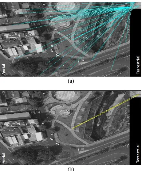
The solution for this drawback is achieved using feature-based matching with the SIFT technique. Homologue points are matched between aerial and terrestrial images to restrict the search space in the aerial image. First the initial EOPs along with their standard deviations and GCP coordinates are used to calculate the initial dimension of the search space. Next, the SIFT technique is applied. However, a filtering must be performed to eliminate mismatches, as displayed in Figure 2(a).
(a)
(b)
Figure 2. (a) Matches between a large aerial image (on the left) and a terrestrial image (on the right). (b) Correct matches after
filtering.
The parameters of a Helmert geometric transformation (scale, rotation and two translations) (Mikhail et al., 2001) between The International Archives of the Photogrammetry, Remote Sensing and Spatial Information Sciences, Volume XL-3/W1, 2014
the matched pairs are estimated, and candidate correct matches are selected by using a majority voting procedure (Skea et al., 1993). From previous approximated scale and rotation values, the transformation translation parameters are computed and stored in accumulation matrix to identify which matches have similar translations. The subset of extracted matches is again adjusted using Helmert transformation to remove remaining incorrect matches. At the end, a set of true matches is available, reducing the search space significantly. Then, a point transfer function can be defined between the aerial and terrestrial images by using the matches. Figure 2(b) exemplifies the filtering of matches between a large aerial image with 900 × 900 pixels and a vertical terrestrial image with 35 × 35 pixels.
3.3 GCP location
GCPs are located in the aerial images using the 2D geometric transformation function previously defined, which projects the points close to their correct positions.
Image chips of GCPs are oriented and resampled to be similar to the aerial images. The optimum chip size is determined based on the best similarity achieved by the cross-correlation coefficient when comparing the terrestrial chip and its respective aerial patch. This area-based matching technique is applied to automatically locate the match point. Figure 3(a) displays an example of a terrestrial chip (25 × 25 pixels) considering a GCP at its centre, and its corresponding aerial patch in (b).
(a) (b)
Figure 3. (a) A terrestrial chip with GCP (centre of the chip) and (b) the corresponding aerial patch.
Next, an adaptive LSM (Gruen, 1996) is used to match the terrestrial chip with the aerial patch with sub-pixel precision. The adjustment is iteratively performed with geometric and radiometric parameters, and small differences are labelled and excluded from the set of observations to improve the parameter estimation. Such differences can be uncommon objects, or shadows as shown in Figure 4. More details on this refinement step are presented in Berveglieri and Tommaselli (2013).
(a) (b) (c)
Figure 4. An example of elimination of differences: (a) aerial patch, (b) terrestrial chip, and (c) labelled differences to be
excluded from the LSM adjustment.
4. EXPERIMENTAL RESULTS AND ANALYSIS
The methodology was applied to multi-scale images to validate the strategy of search space reduction and automatic location of GCPs.
The proposed algorithms to reduce the search space and to locate GCPs were implemented in C/C++, and the SIFT technique used scripts developed in Matlab and available in Lowe (2005).
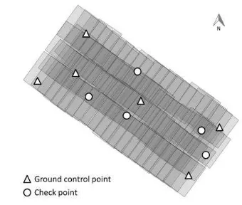
An image block was used for the experiments considering 83 aerial images arranged in four flight strips and acquired with a Hasselblad-60MP over Presidente Prudente – Brazil (see Figure 5). Six GCPs and five check points were used in a bundle block adjustment with the commercial ERDAS-LPS software. The parameters simulating an indirect sensor orientation were configured with the following standard deviations:
s = 2 m in position and s = 2° in attitude for the initial EOPs;
s = 0.05 m for the GCPs in the object space, according to the surveying accuracy;
s = 0.5 pixels for the image coordinates.
Figure 5. Geometric arrangement of six GCPs and five check points over the image block.
The project of ERDAS-LPS was also used to perform: automatic generation of tie points and point transfer of image coordinates. The GCPs were located over the images using: monoscopic manual measurements and the proposed technique (automatic measurement).
Each GCP image coordinate of both measurements was measured in a single image and then automatically transferred to homologue positions by the LPS, which uses LSM. The same project was used for the measurements in the two groups of experiments, changing only the image coordinates manually. A comparison of results was performed to assess the improvement when using the automatic technique.
Figure 6 presents the values of Root Mean Square Errors (RMSEs) resulting from the bundle adjustment at six GCPs in the object space. The automatic technique achieved values less than 0.013 m in planimetry, whereas the manual measurement obtained values less than 0.024 m. The RMSEs in the Z-coordinate were the same (0.031 m) in both measurements The International Archives of the Photogrammetry, Remote Sensing and Spatial Information Sciences, Volume XL-3/W1, 2014
due to the point transfer automatically performed by the LPS
Figure 6. Comparison of RMSEs on GCPs in the object space after bundle adjustment.
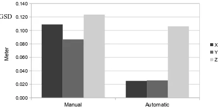
Figure 7 displays a bar graph with the RMSEs obtained in five check points in the object space. The manual technique resulted in discrepancies of 0.11 and 0.08 m for X and Y, respectively. These results were significantly improved with the automatic technique that achieved RMSEs less than 0.025 m for both X and Y. The discrepancies in Z-coordinate were also improved with the automatic technique, which indicated RMSEs smaller than 1 GSD, whereas the manual technique obtained RMSEs greater than 1 GSD.
Manual Automatic
Figure 7. Discrepancies from five check points in the object space.
The improvement in the accuracy of the check points can also be expressed in percentages when comparing the automatic with the manual measurement. The accuracy was improved in planimetry by approximately 70% and in heights by 14%.
The greatest effect of the proposed technique was in planimetry. Using the GSD as a unit, the accuracy achieved in planimetry was approximately 0.9 GSD when using the manual technique and 0.2 GSD with the automatic technique. The σ naught values of the bundle adjustment for both techniques were similar and resulted in 0.33.
5. CONCLUSIONS
A study has been conducted to automatically locate GCPs in large search space in aerial images when the DG data being used as initial approximations have low quality or are not available. The methodology presented a combination of feature-based matching with the SIFT technique and area-based matching with sub-pixel refinements.
The experiments performed with multi-scale images demonstrated sufficient reduction of the search space to apply area-based matching technique in the automatic location of GCPs successfully. To assess the automatically measured coordinates, a bundle block adjustment considering an indirect sensor orientation with inaccurate EOPs was performed, and discrepancies were analysed on GPCs and check points. The developed to further improve the approach, automating the terrestrial chip generation and using scenes from any area containing distinguishable features.
REFERENCES
Berveglieri, A., Tommaselli, A.M.G., 2013. Automatic measurement of ground control points with terrestrial control chips for bundle block triangulation. In: Proceedings of the Joint CIG Annual Conference and EOGC’2013. Canadian Institute of Geomatics, Toronto, Canada.
Brown, D. C. 1971. Close-range calibration. Photogrammetric Engineering. 37(8), pp. 855–866.
Fraser, C. S., Hanley, H. B., Yamakawa, T. 2001. Sub-metre geopositioning with ikonos geo imagery. In: ISPRS Joint Workshop. Hannover, Germany.
Gruen, A., 1996. Least square matching: a fundamental measurement algorithm. In: Atkinson, K. B. (Ed.), Close range photogrammetry and machine vision. Whittle Publishing, Bristol, pp. 217–255.
Heipke, C. 1997. Automation of interior, relative, and absolute orientation. ISPRS Journal of Photogrammetry and Remote Sensing 52(1), pp. 1–19.
Kraus, K., 2007. Photogrammetry: geometry from images and laser scans. 2nd. de Gruyter, Berlin, pp. 286-365.
Lowe, D.G., 1999. Object recognition from local scale-invariant features. In: Proceedings of the International Conference on Computer Vision, Corfu, Greece. II: 1150–1157.
Lowe, D.G., 2004. Distinctive image features from scale-invariant keypoints. International Journal of Computer Vision. pp. 91–110.
Lowe, D.G. 2005. Demo Software: SIFT Keypoint Detector. http://www.cs.ubc.ca/~lowe/keypoints/ (19 Nov. 2013).
Malmström, H., 1986. Measuring ground control points for satellite image rectification. In: Schriftenreihe Des Instituts Für Photogrametrie Der Universität. Stuttgart. pp. 127–135.
Marcato Junior, J., Tommaselli, A.M.G. 2013. Exterior orientation of CBERS-2B imagery using multi-feature control and orbital data. ISPRS Journal of Photogrammetry and Remote Sensing 79, pp. 219–225.
GSD
Mikhail, E.M, Bethel, J.S., McGlone, C.J. 2001. Introduction to Modern Photogrammetry. John Wiley & Sons, New York, pp. 351-386.
Schenk, T. 2004. From point-based to feature-based aerial triangulation. ISPRS Journal of Photogrammetry & Remote Sensing. pp 58: 315–329.
Skea, D., Barrodale, I., Kuwahara, D., Poeckert, R. 1993. A control point matching algorithm. Pattern Recognition 26(2), pp. 269–276.
Tommaselli, A.M.G., Tozzi, C.L. 1996. A recursive approach to space resection using straight lines. Photogrammetric Engineering & Remote Sensing. 62(1), pp. 57–66.
ACKNOWLEDGMENTS
The authors would like to thank the Fundação de Amparo à Pesquisa do Estado de São Paulo (FAPESP) p. 2010/16954-5 and CNPq (305111/2010-8) for financial support and Sensormap Geotecnologia for providing aerial images.