SANDWICH CONCRETE PANEL REINFORCED WITH SISAL
advantages to provide high specific strength and low density. This paper introduces the application of sisal fiber mesh to reinforce wall sandwich concrete panel for housing and building industries. The fibers were tested initially to obtain its properties included tensile strength. Ten concrete walls were designed and investigated under axial and flexural loading. The walls consisted of sandwich walls and normal walls with three various types were considered. The wall section was 300x100 mm and 300x70 mm with length of 700 mm. The sisal fiber mesh reinforcements were embedded in two sides of wall by about 15 mm from the outer surface of the wall. Experimental results showed that the axial compression did not affect by the presence of sisal fiber mesh. However, flexural strength of the wall increased 80% and 32% for normal wall and sandwich wall respectively. The thickness of the wall has also identified had significant effect to the flexural strength. Increasing wall thickness from 70 mm to 100 mm will improve flexural strength to 1.43 and 1.98 for sandwich fibers wall and normal wall respectively.Key Words: sisal, sandwich wall, lightweight concrete, compression strength, flexural strength
INTRODUCTION
Plant fibers such as pineapple fiber, ramie, jute, banana fiber, flax, coir with different species in different parts of the world are generally used for rope, sacks, fishing nets, mats, mattresses, pillows, bags, souvenirs and floor coverings (Saxena et al., 2000). It also been reported that the plant fibers to replace synthetic fibers in polymer composite materials can reduce the costs. In recent years, the use of plant fibers were widely implemented in polymer composites materials with their advantages to provide high specific strength and low density. Bismarck et al (2006) explained that the fiber plants are available in nature with low price of unit volume. This natural fiber can be considered in the industry because of its light weight, economic and sustainable material (Khoatane, 2008).
Sisal fiber is also used in combination with synthetic fibers in hybrid composites as has been done by John and Naidu (2004) by applying the sisal fibers combined with fiber glass to reinforce unsaturated polyester. Variation of tensile strength of polyester-fiber composite hybrid sisal and glass fiber is affected by the composition of the fiber. Hybrid composite tensile strength increases with increasing fiber glass portion. Hybridization was also performed by Silva et al. (2008) using combination of curauá plant fiber and glass fiber. This hybridization of the composit materials can effectively reduce water absorption.
Hybridization of weaving banana fiber and glass fiber to reinforce polyester composit is significantly increased the capacity of two-dimensional loading. The optimum mechanical properties can be obtained by variation of volume fraction, woven patterns and pattern coating. This composite material can reduce the production cost at similar strength compare to the use of composite glass fiber reinforcement alone (Laly, 2005).
The above explanation described that the use of natural fibers can achieve a good modulus elasticity under low specific gravity (Mathur, 2005). Thus pineapple fibers including fiber plants have prospect to be used as reinforcement for structural materials such as walls. In addition, the use of natural fibers materials is environmentally friendly.
Concrete research has been done in relation of sandwich beam and column components to reduce the weight of the structure (Akmaluddin and Murtiadi, 2013). However, very limited information available to the use of sisal fiber meshes on sandwich concrete elements. Therefore, the main objective of this study is to investigate the effect of sisal fiber mesh on precast concrete walls under compressive and flexural loadings for possibility applications in building industries.
EXPERIMENTAL PROGRAM
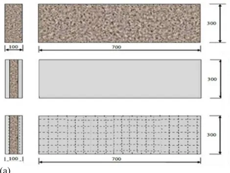
Designed specimen with two type walls of normal wall and sandwich wall were constructed to achieve the objective of this study. The walls thickness of 100 and 70 mm were considered. Normal wall was made of pumice lightweight concrete and sandwich wall was constructed using lightweight concrete as a core and mortar as a skin. Skin thickness was 15 mm and core thickness have two varies of 70 mm and 40 mm to produce 100 mm and 70 mm wall thickness respectively.
The walls were designed with and without sisal fiber mesh reinforcement of 6 mm diameter with opening of 50 mm. The walls were also designed to be tested under axial compression and flexure. Figure 1 shows typical specimen of wall with 100 mm thickness.
Figure 1 Wall Specimen of 100 mm Thickness
The wall variations were designated as presented in Table 1. The wall designation indicated wall types, fiber mesh application, thickness and testing types. For example SWF-7F means sand sandwich (SW) wall containing fiber (F) mesh with 7cm thickness for testing under flexure (F). Another example NWF-10C
indicated normal wall (NW) with fiber (F) mesh content and a thickness of 10 cm for the test under compression (C). Thus, in the discussion later on will refer to the wall designation as presented in the table.
Table 1
Wall Designation
Wall_ID Type of Test b (mm) h (mm) L (mm)
SWF-7F
Flexural
300 70 700
SWF-10F 300 100 700
NW-10F 300 100 700
NW-7F 300 70 700
NWF-7F 300 70 700
SWF-7C
Axial Compression
300 70 700
SWF-10C 300 100 700
NWF-10C 300 100 700
NW-10C 300 100 700
NW-10F 300 100 700
Materials
Lightweight concrete strength of 12 MPa and mortar strength of 17 MPa were designed. Pumice aggregate with 10 mm maximum size was used in the concrete mixture, whilst the cement proportion to the sand of 1:3 was used in the mortar to produce sandwich wall skin. Mixed design of the target strength of 12 MPa is shown in the lightweight concrete mixture in Table 2.
Table 2
Lightweight Concrete Mixture
Material Composition
Cement kg/m3 367
Water (kg/m3) 343
w/c 0.94
Sand kg/m3 473
Pumice kg/m3 378
Specimen preparation
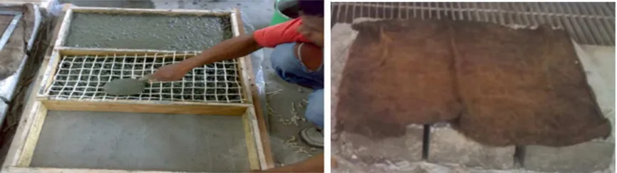
Two set molds consisted of three hole of 300x700 mm and of 100 mm thickness were made using wood thick-block as can be seen in Figure 2. To cast the sandwich wall containing fiber mesh, three steps were done. Firstly skin were construct as follows, mortar was poured into the mould until the thickness of 15 mm was achieved. A fiber mesh then laid-up on the mortar layer immediately then re-poured mortar until produce mortar total thickness of 20 mm. Secondly, once the mortar layer finished then pumice lightweight concrete core was poured into the mould up to 60 mm thickness. Finally the core then covered with mortar of 5 mm thick and fiber mesh were laid up in the mortar layer then poured mortar into the mold until 20 mm total thickness. After completion the steps the mold was then released in the next day and sandwich wall specimen were covered using wet burlap and plastic sheet for 27 days. Figure 2 shows casting of sandwich wall and its curing process.
Figure 2 Sandwich Wall Casting and Curing Process
Instrumentation and Test Procedure
determine the core and skin sandwich wall strength respectively.
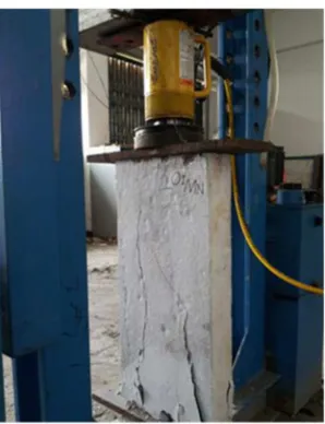
Compression testing was done by placing a wall specimen in the steel frame and was clamped in such a way as seen in Figure 3. Steel plates of 10 mm were put on the bottom and the top of the specimen. Load cell was placed and acting parallel to the axis of the wall. Load cell was powered by hydraulic jack with capacity of 500 kN. As the wall loaded, lateral deflection was measured using dial gauge in left and right direction at the center of the wall.
Initially, a small load was applied to ensure equipment installed was working properly. Figure 3 shows equipment and set up wall for axial compression test.
Figure 3 Wall under Axial Compression Test Until Failure
Flexural test was done by placing the specimen in a standard flexural test frame as can be seen in Figure 4 below. A transducer was put and set up in the top of the specimen to measured vertical deflection. Two point loads was applied in the flexural test. Setup of flexural test can be seen clearly in Figure 4 below. Loads and deflections were directly monitored and recorded automatically using computer software data acquisition.
Figure 4 Wall Flexural Test Set-up (left) and the Wall After Testing (right)
TEST RESULTS AND DISCUSSION
Behavior of concrete wall under axial loading
Figure 5 Wall Behaviors under Axial Compression Test
The more load was added the dials reading change in the bending direction indicated by the inverse reading to the initial reading as can be seen in Figure 5 above. After that the wall experience deformation in one direction up to a maximum of 1.3 mm at 60 kN (20% Pu) then both sides of the wall further deformed in the
same direction. Up to this load level loading cracks did not occur in the wall specimen. Further deformation was not recorded until the maximum load applied. At the loading reaches 70% Pu, then the straight-line cracks appeared on the surface of the wall. The cracks number increased as the loading increased and eventually the wall specimen failure.
Walls Compression Strength Capacity
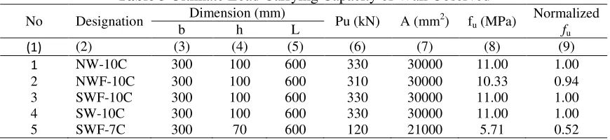
Wall strength capacities under compression loading were obtained for five wall specimen tested in this study. Table 3 shows the test results of the various specimens carried out.
Table 3 Ultimate Load Carrying Capacity of Wall Observed
No Designation Dimension (mm) Pu (kN) A (mm2) fu (MPa)
Normalized fu
b h L
(1) (2) (3) (4) (5) (6) (7) (8) (9)
1 NW-10C 300 100 600 330 30000 11.00 1.00
2 NWF-10C 300 100 600 310 30000 10.33 0.94
3 SWF-10C 300 100 600 330 30000 11.00 1.00
4 SW-10C 300 100 600 330 30000 11.00 1.00
5 SWF-7C 300 70 600 120 21000 5.71 0.52
Normal wall with 10 mm thickness (NW-10C) was used as a control specimen. This specimen failure at 330 kN loading applied produce strength capacity of 11 MPa. In general, all walls with 100 mm thickness almost failure at the average load of 325 kN. When those specimens compared with NW-10C, it can be concluded that the presence of sisal fiber mesh and wall type did not affect significantly load carrying capacity of the wall under compression. These clearly show in column (9) of Table 3 which indicated by the value of normalized fu close to 1. This also applies to any type of wall as long as they have the same
thickness. Therefore, no need similar comparison for 70 mm wall thickness. Thus simply it can be compared a 70 mm wall with any 100 mm wall as presented in Table 3. The value obtained is 0.52 which produced from 5.714/11 = 0.52. With regard to cross section area of the wall in column (7) of Table 3 it can be obtained ratio cross section of 0.7 between 70 mm and 100 mm wall thicknesses. In another word 70 mm wall have section area 30 % less than area cross section of 100 mm thickness. This means that with only 30% cross section area decreased, the strength capacity of the wall decrease almost 50%.
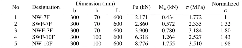
Wall Flexural Strength
Table 4 Wall Flexural Strength Observation
When comparing all 70 mm wall thickness. It can be said from Table 4 that in general the presence of fiber mesh increased the wall ability to resist flexure of 1.77 MPa, 2.335 MPa and 3.184 MPa for NW-7F, SWF-7F and NWF-SWF-7F respectively. The increasing value of the wall ability denoted as normalized is used. Thus sandwich wall with fiber (SWF-7F) have 1.32 times bigger strength ability of normal wall (NW-7F). Similarly, normal wall with fiber (NWF-7F) have flexural strength bigger of 1.80 than normal wall (NW-7F).
In another word, sandwich wall containing fiber mesh has flexural strength 32% bigger than that of a control wall and normal wall containing fiber mesh increased flexural strength of 80% to the control wall. It can also be seen in the table, the wall thickness will have significant effect to the flexural strength. Normalized to NW-7F, the flexural strength of SWF-10F and NW-10F will be 1.43 and 1.98 respectively.
CONCLUSION
Brief conclusions are summarized as follows:
• The addition of sisal fiber mesh on the walls does not significantly increase the wall resistance to
the compression load.
• The addition of sisal fiber mesh on the normal wall increased the flexural strength of 80%, while
the sandwich increased by about 32% flexural strength.
• The thickness of the wall has significant effect to the flexural strength. Increasing wall thickness
from 70 mm to 100 mm will improve flexural strength to 1.43 and 1.98 for sandwich fibers wall and normal wall respectively.
ACKNOWLEDGEMENT
The Authors would like to thank the Director of Directorate Research and Community Service for the financial support through the National Strategy Research Scheme under Directorate General of Higher Education, Ministry of National Education and Culture, Republic of Indonesia.
REFERENCES
Akmaluddin and S. Murtiadi. 2013. Hybrid Precast Concrete Column and Sandwich Concrete Beam under Static Loading. Procedia Engineering V54 pp. 286 – 298, Elsevier Ltd.
Bismarck, A. Baltazar, Y. J. Sarlkakis, K. 2006. Green Composites as Panacea? Socio-Economic Aspects of Green Materials. Environment, Development and Sustainability. V 8 No 3. Pp. 445–463.
John, K. and Naidu, S.V. 2004. Tensile Properties of Unsaturated Polyester-Based Sisal Fiber–Glass Fiber Hybrid Composites, Journal of Reinforced Plastics and Composites, V. 23. 1815 p.
Khoatane, M. C. Vorster, O. C. Sadiku, E. R. 2008. Hemp Fiber-Reinforced Pentene/ Polypropylene Copolymer: The Effect of Fiber Loading on the Mechanical and Thermal Characteristics of the Composites, Journal of Reinforced Plastics and Composites, V 27. 1533p.
Laly A. P. Potschke, P. Habler, R. Thomas, S. 2005. The Static and Dynamic Mechanical Properties of Banana and Glass Fiber Woven Fabric-Reinforced Polyester Composite, Journal of Composite Materials, V. 39. 1007p.
Mathur, V. K. 2005. Composite Materials from Local Resources, Construction and Building Materials. V20 No. 7. pp. 470–477.
Naiola, P. B. 1986. Tanaman Budidaya Indonesia Nama Serta Manfaatnya. CV. Yuasaguna. Jakarta. Saxena, M., Asokan, P. and Morchhale, R.K. 2000. Jute Composite as Wood Substitute, Building Materials
News Letter. Women in Urban Governance, World Habitat Day, Building Materials and Technology Promotion Council, New Delhi, India, pp. 67–70.