POWER FACTOR CORRECTION FOR VARIOUS TYPE OF MAGNETIC FLUX BALLAST FLOURESCENT LAMP
MOHD ALL FADZIL BIN NASIR
This Report Is Submitted In Partial Fulfillment Of Requirements For The Degree Of Bachelor In Electrical Engineering
(Power Electronic and Drives)
Faculty of Electrical Engineering
UNIVERSITI TEKNIKAL MALAYSIA, MELAKA
ii
“I declare that this report entitle “Power Factor Correction for Various type Of Magnetic
Flux” is the result that my own research except as cited in the references. The report has not been accepted for any degree and is not concurrently submitted in candidature of any other degree.
Signature : ……….
Student :MOHD ALL FADZIL BIN NASIR
iii
ACKNOWLEDGEMENTS
First of all, I would like to express my thankfulness and gratitude to Allah S.W.T who has given me all the strength complete this final year project and also prepare this report.
With this opportunity, I would like to express my gratitude to the Faculty of electrical Engineering (FKE), Universiti Teknikal Malaysia Melaka (UTeM) generally and especially to my supervisor Mr. Hairul Nizam Bin Talib for his help, advices and guidance during completely this project.
iv
ABSTRACT
v
ABSTRAK
vi
TABLE OF CONTENTS
CHAPTER TITLE PAGE
TITLE PAGE i
ADMISSION ii
ACKNOWLEDGMENT iii
ABSTRACT iv
ABSTRAK v
TABLE OF CONTENTS vi
LIST OF TABLES ix
LIST OF FIGURES x
LIST OF APPENDICES xiii
1 INTRODUCTION 1
1.1 Introduction 1
1.2 Problem Statements 2
1.3 Project Objective 2
1.4 Project Scope 3
2 LITERATURE REVIEW 4
vii
2.1.1 Fluorescent Lamp Parts 4 2.1.2 Fluorescent Lamp Operation 5 2.1.3 Fluorescent Lamp Circuit Operation 6 2.2 Electrical Characteristic of Lamp 6 2.2.1 Lamp Starting and Run Up 7 2.2.2 Lamp Running and Stability 7
2.3 Magnetic Ballast 8
2.3.1 The Preheat Circuit 9 2.3.2 Lead-lag Switch 10 2.3.3 Series-connected magnetic Ballast 10
2.4 Starter of Lamp 11
2.5 Power Factor 12
2.5.1 Power Factor Explanation 12 2.5.2 Power Factor Correction 13
3 METHODOLOGY 15
3.1 Flow chart 15
3.2 OrCAD 17
3.3 Fluke Power Quality Analyzer 19 3.3.1 Measuring Lighting Load 20
4 RESULTS 26
4.1 Calculation and simulation 26 4.1.1 Magnetic ballast 26 4.1.2 Effect of Power Factor Selected 32
Ballast
viii
4.1.4 Power Factor Improvement for 35 IL LEMAX magnetic ballast
4.2 Measurement from the 38 Fluke Analyzer
4.2.1 IL LEMAX 38
4.2.2 9 unit florescent lamp with the LITE 41 magnetic ballast
4.3 Discussions from the results 43 4.3.1 Power Factor Comparison before PFC 44 4.3.2 Power Factor Comparison after PFC 45 4.3.3 9 Unit Fluorescents Lamp 46
5 CONCLUSION AND RECOMMENDATION 48
5.1 Conclusion 48
5.2 Recommendation 48
LIST OF REFERENCES 49
ix
LIST OF TABLES
TABLE TITLE PAGE
x
LIST OF FIGURES
FIGURE TITLE PAGE
2.1 The electromagnetic spectrum 4
2.2 The fluorescent lamp 5
2.3 Structure of fluorescent lamp 5
2.4 Circuit of fluorescent lamp 6
2.5 Magnetic Ballast 8
2.6 Connection Plat E& I 8
2.7 Winding copper at the Plat 9
2.8 Pre-Heat circuit 9
2.9 Lead-lag Switch for two lamps 10
2.10 Equivalent circuit of series connected 10 ballasts
2.11 Phase displacement of VM (Supply), 11 VB (Ballast), and VL (Lamp)
2.12 Starter of Lamp 11
2.13 Place of Starter lamp 11
2.14 TH=Cathode preheats time, 12
TT= Total time to start
2.15 Phase displacement between 13
voltage and current
2.16 Power Factor Corrections 13
2.17 Phase displacement between voltage 14 and current after Power Factor Correction
xi
3.1 Flow chart of magnetic ballast for 15 power factor improvement construction
3.2 OrCAD Capture CIS 17
3.3 Schematic Diagram 17
3.4 Simulation Setting 18
3.5 Graph Simulation 18
3.6 Total Power Dissipation 19
3.7 Fluke Quality Analyzer 19
3.8 Lighting Load Connection 21
3.9 Power and Power Factor Measurement 23 Connection
3.10 Power Menu 23
3.11 Total Harmonic Distortion 24
Measurement Connection
3.12 Total Harmonic Menu 25
4.1 Resistive lamp model 26
4.2 Magnetic ballast simplified model 27
4.3 Type of magnetic ballast 27
4.4 Impedance diagram 28
4.5 Simulation model of the magnetic 29 ballast IL LEMAX
4.6 Simulation result of output voltage 31 waveform for the magnetic ballast (IL LEMAX)
4.7 Phase displacement for the magnetic 32 ballast IL LEMAX
4.8 Simulation result of current magnetic 33 ballast IL LEMAX
4.9 Falanke capacitor 34
4.10 Simulation model for IL LEMAX 36
xii
4.11 Phase Displacement between voltage and 36 current(IL LEMAX)
4.12 IL LEMAX after Power Factor Improvement 26
4.13 3 Unit Lamp 38
4.14 9 unit fluorescent lamps with LITE 41 magnetic ballast
xiii
LIST OF APPENDICES
APPENDIX TITLE PAGE
A Project Planning 50
B Simulation Model magnetic ballast 51 XC, EFR and LITE
C Output voltage waveform ballast 52
XC, EFR and LITE
D Magnetic ballast EFR 53
E Magnetic ballast XC 54
F Magnetic ballast LITE 55
CHAPTER 1
INTRODUCTION
1.1 Introduction
2
1.2 Problem statements
Based on the problem faced nowadays which is an increase in electricity rated, a research in conduct on other electricity usage that can produce the saving the power consumption In this project, power saving can be done by reducing total power consumption used by electrical appliance. Power consumption can be decreased with increasing power factor for all electrical appliance for instance at fluorescent lamp. The magnetic ballast at fluorescent lamp has the power factor as low as 0.5. Several model of magnetic ballast have a high quantity and concentration of winding within a piece of equipment reduces the power factor. In this project, magnetic ballast fluorescent lamp will be selected and all of its electrical parameter will be analyze such as starting voltage, current, steady-state condition, power consumption, power factor and harmonic. Power factor improvement will applied to the selected ballast model with addition suitable done of power factor correction.
1.3 Project Objective
These are the objectives of this project:
1. Identify the electrical model for selected type magnetic ballast fluorescent lamp.
2. To analysis the electrical parameter such as starting voltage, current, steady-state condition, harmonic, power consumption and power factor.
3
1.4 Project Scope
These are the scope of this project:
1. This project is analysis on the selected three type of magnetic ballast, there are IL LEMAX, XR, EFR, LITE fluorescent lamp.
2. Electrical model of magnetic ballast will be calculated and simulated based on the measurement of actual referred model.
3. Measurement the parameter of magnetic ballast from the lab test and simulation based on the actual model.
CHAPTER 2
LITERATURE REVIEW
2.1 Fluorescent Lamp
A fluorescent lamp can be defined as a low-pressure mercury-vapor electrical-discharge having the inside wall of glass bulb or tube coated with fluorescent material so that the ultraviolet (UV) radiation from the discharge of phosphor converted to visible radiation into the light of an acceptable color. Electrical energy dissipated in the electrical discharge is converted mainly into electromagnetic radiation in the ultraviolet (UV) region of spectrum [1]. The visible portion of the spectrum covers the wavelength range from approximately 380 nm to 780 nm as shown in Figure 2.1.
Figure 2.1: The electromagnetic spectrum [1]
2.1.1 Fluorescent Lamp Parts
Basically, a fluorescent lamp is made up of five components:
Glass Tube - coated on the inside with fluorescent powder called Phosphor Two Electrodes (cathode) – coated with emitter, supported by a glass mount
structure and sealed at the end of the tube.
5
Mercury Vapor – small amount(less than 20mg), which vaporizes during the lamp operation.
Lamp Cap – lamp cap cemented to each end of the tube to connect the lamp to the lighting circuit.
Figure 2.2: The fluorescent lamp [9]
2.1.2 Fluorescent Lamp Operation
When the circuit is energized, electricity heats the cathodes. See Figure 2.3. The cathodes are coated with material which, when heated, emits electrons. The electrons establish an electric arc between the cathodes at opposite ends of the tube. The electrons collide with the mercury atoms, causing mercury to emit invisible ultra-violet radiation [2]. The ultra-violet is absorbed by the phosphor coating on the tube and re-radiated as visible light.
6
2.1.3 Fluorescent Lamp Circuit Operation
Figure 2.4 shows the basic fluorescent lamp circuit. The circuit must contain a ballast to limit the current and a starter to provide the pre-heat conditions. Initially the starter switch closes so the two cathodes are connected in series. Current flows and the cathodes heat up emitting electrons. After a short time the starter switch opens so voltage is applied across the tube. If sufficient electrons are available an arc is struck and the starter plays no further part until the next starting operation. If there are insufficient electrons, the tube will flicker, fail to start, and the starter will repeat the heating of the cathodes. The ballast limits the current to a safe and appropriate level for the power of lamp. Without the ballast, the current would increase to a high level and the lamp would destroy itself [9].
Figure 2.4: Circuit of fluorescent lamp [10]
2.2 Electrical Characteristic of Lamp
7
2.2.1 Lamp Starting and Run Up
i. Starting Voltage
A higher and normal voltage is required to initiate the ionization process in discharge lamps. If the supply voltage is insufficient the additional starting voltage may be generated by transformers, starting devices, semi-resonant circuits or pulse producing components. The voltage required for lamp starting may depend on the external temperature, humidity and any electric fields [2].
ii. Lamp run-up
The time of run-up depends on the lamp, the circuit and the ballast. Fluorescent lamp stabilizes in a very short time and gives full light output very shortly after starting. Discharge lamps containing only rare gas required no run-up time and the electrical characteristics do not change significantly after starting [9].
2.2.2 Lamp Running and Stability
i. Current runaway
In the arc discharge region the characteristics has a negative slope due to the cumulative effect of electron-atom collisions producing ionization. To prevent current runaway and ensure stable operation from a constant voltage power supply the negative characteristics must be counterbalanced by circuit element having positive characteristics. This element is called ballast [2].
ii. Alternating current operation
8
effective impedance of the lamp is approximately equivalent to a non-linear resistance and an inductance in series.
2.3 Magnetic Ballast
Figure 2.5: Magnetic Ballast
Magnetic ballast is device intended to limit the amount of current in an electric circuit. All fluorescent lamps require ballast for starting operation to generate the required starting voltage and during running condition for limiting the alternating current us the lamp impedance becomes very low during running. For higher-power installations too much energy would be wasted in resistive ballasts, so alternatives are used that depend upon the reactance of inductors, capacitor or both. All electromagnetic ballasts are basically inductor having core made up of iron laminations and winding made up of copper or aluminum wire [9].
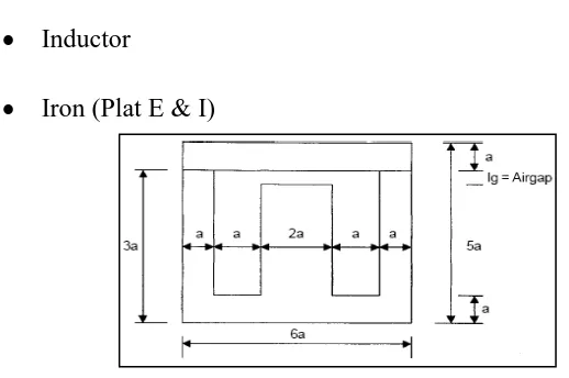
Component in magnetic ballast: Inductor
Iron (Plat E & I)
9
Figure 2.7: Winding copper at the Plat
The ballasts made to operate fluorescent lamp are not all the same. Each specific type of fluorescent lamp requires its own ballast design. Both the lamps and the ballasts are categorized according to the method by which they start and operate. The first fluorescent lamps were instants-started.
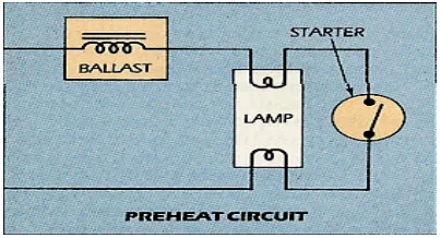
2.3.1 The Preheat Circuit
The preheat circuit was developed next as a way to reduce the ballast size, weight and cost. The lamp filaments are preheat prior to lamp ignition, but separate switching device is needed to start the lamp Most common used is referred to as the ‘glow bottle” starter.
10
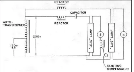
2.3.2 Lead-lag Switch
Almost at the very onset of fluorescent lamp usage, it was found desirable to operate two lamps from the same ballasts. One of the lamps is connected in series with an inductor, while the other is in series with a capacitor plus an inductor, which it still needed to help limit the current. The overall circuit will then provide a power factor close to unity.
Figure 2.9: Lead-lag Switch for two lamps [11]
2.3.3 Series-connected magnetic Ballast
The series-connected choke ballast produces a phase displacement of 55 to 65 degrees between supply voltage and lamp current and this enables a hanger sustaining voltage to be available at the start of every half-cycle(Figure 2.11.a). Operation is more stable and the current distortion is low (Figure 2.11.b). The prime function of ballast is to prevent current runaway and to operate the lamp at its correct electrical characteristics. The ballast should be efficient, ensure proper lamp starting and ensure stable lamp run-up and operation. Supply voltage in the range 220-240 V, a nominal lamp voltage in the 70-145 V.
11
a)
b)
Figure2.11: Phase displacement of VM (Supply), VB (Ballast), and VL (Lamp)
2.4 Starter of Lamp
A fluorescent light does not have the usual glowing filament of an incandescent bulb, but instead contains a mercury vapor that gives off ultraviolet light when ionized. The ultraviolet light makes particles that coat the inside of the tube, and these particles glow.
Figure 2.12: Starter of Lamp [9]
Fluorescent starters are used in several types of fluorescent lights. The starter is there to help the lamp light. When voltage is applied to the fluorescent lamp, here's what happens because the starter (which is simply a timed switch) allows current to flow through the filaments at the ends of the tube. Secondly, the current causes the starter's contacts to heat up and open, thus interrupting the flow of current and since the lighted fluorescent tube has a low resistance, the ballast now serves as a current limiter.
![Figure 2.1: The electromagnetic spectrum [1]](https://thumb-ap.123doks.com/thumbv2/123dok/631727.76529/17.595.165.448.464.574/figure-the-electromagnetic-spectrum.webp)
![Figure 2.3: Structure of fluorescent lamp [9]](https://thumb-ap.123doks.com/thumbv2/123dok/631727.76529/18.595.156.424.522.711/figure-structure-of-fluorescent-lamp.webp)
![Figure 2.4: Circuit of fluorescent lamp [10]](https://thumb-ap.123doks.com/thumbv2/123dok/631727.76529/19.595.149.462.320.446/figure-circuit-of-fluorescent-lamp.webp)
![Figure 2.13: Place of Starter Lamp [9]](https://thumb-ap.123doks.com/thumbv2/123dok/631727.76529/24.595.183.383.85.204/figure-place-of-starter-lamp.webp)
