i
INNOVATIVE OPTICAL SENSOR TO DETERMINE VIBRATION
UMI HANI BINTI ABDUL HAMID
This report is submitted in partial fulfillment of the requirements for the award of Bachelor of Electronic Engineering (Telecommunication Electronics) With Honours
Faculty of Electronic and Computer Engineering Universiti Teknikal Malaysia Melaka
ii
UNIVERSTI TEKNIKAL MALAYSIA MELAKA
FAKULTI KEJURUTERAAN ELEKTRONIK DAN KEJURUTERAAN KOMPUTER
BORANG PENGESAHAN STATUS LAPORAN
PROJEK SARJANA MUDA II
Tajuk Projek : INNOVATIVE OPTICAL SENSOR TO DETERMINE VIBRATION Sesi pengajian : 2008/2009
Saya UMI HANI BT ABDUL HAMID (HURUF BESAR)
mengaku membenarkan Laporan Projek Sarjana Muda ini disimpan di Perpustakaan dengan syarat-syarat kegunaan seperti berikut:
1. Laporan adalah hakmilik Universiti Teknikal Malaysia Melaka.
2. Perpustakaan dibenarkan membuat salinan untuk tujuan pengajian sahaja.
3. Perpustakaan dibenarkan membuat salinan laporan ini sebagai bahan pertukaran antara institusi
pengajian tinggi.
4. Sila tandakan ( √ ) :
SULIT*
(Mengandungi maklumat yang berdarjah keselamatan atau kepentingan Malaysia seperti yang termaktub di dalam AKTA RAHSIA RASMI 1972)
TERHAD*
(Mengandungi maklumat terhad yang telah ditentukan oleh organisasi/badan di mana penyelidikan dijalankan)
TIDAK TERHAD
Disahkan oleh:
__________________________ ___________________________________
iii
“I hereby declare that this report is the result of my own work except for quotes as cited in the references.”
iv
“I hereby declare that I have read this report and in my opinion this report is sufficient in term of the scope and quality for the award of Bachelor of Electronic Engineering (Telecommunication
Electronics) With Honours.”
v
DEDICATION
vi
ACKNOWLEDGEMENT
vii
ABSTRACT
viii
ABSTRAK
ix
TABLE OF CONTENTS
CHAPTER TITLE PAGE
PROJECT TITLE i
REPORT STATUS VALIDATION FORM ii
DECLARATION iii
SUPERVISOR DECLARATION iv
DEDICATION v
ACKNOWLEDGEMENT vi
ABSTRACT vii
ABSTRAK viii
TABLE OF CONTENTS ix
LIST OF TABLES xiii
LIST OF FIGURES xiv
SYMBOL, SHORT FORM & TERM LIST xvi
x
I INTRODUCTION 1
1.1 INTRODUCTION OF THE PROJECT 1
1.2 PROJECT OBJECTIVES 2
1.3 PROBLEM STATEMENT 3
1.4 SCOPE OF WORK 4
1.5 METHODOLOGY 5
1.6 REPORT STRUCTURE 6
II LITERATURE REVIEW 8
2.1 INTRODUCTION 8
2.2 OVERVIEW OF THE PROJECT 10
2.2.1 Introduction of optical fiber system 10
2.2.2 Fiber Optic vibration sensor 11
2.2.3 Energy, Velocity, Wavelength, and Frequency 12
2.2.4 Snell’s Laws 13
2.2.4.1 Law of reflection 14
2.2.4.2 Law of refraction 14
2.2.5 Comparison between single mode and multimode 14 2.3 Plastic optic fiber 16
2.4 Properties of optical fiber transmission 16
2.4.1 Attenuation 17
2.4.2 Dipersion 18
xi
2.5.1 Basic operation 20
2.5.2 Microbend application 22
2.6 LASER 23
2.7 Light Dependent Resistor (LDR) 24
2.8 Basic concept of the project 26
III PROJECT METHODOLOGY 28
3.1 PROJECT OUTLINE 28
3.2 PROJECT CHOOSING 28
3.3 PROJECT PLANNING 29
3.4 LITERATURE REVIEW 29
3.5 CIRCUIT DESIGN 30
3.6 HARDWARE DEVELOPMENT 31
3.6.1 Mounted Process 32
3.6.2 Soldering 33
3.6.3 Preparation of Soldering Iron 34
3.6.4 Soldering Process 35
3.7 MEASUREMENT DEVELOPMENT 37
3.7.1 Measurement by using oscilloscope 37
xii
1V RESULT AND DISCUSSION 42
4.1 Results 42
4.1.1 Analysis of total light received at the receiver 43
4.1.2 Observation of indicator alarm 47
4.2 Analysis On Distance Between Tx And Rx 47
V CONCLUSION AND RECOMMENDATIONS 49
5.1 CONCLUSION 49
5.2 RECOMMENDATION 50
REFERENCES 51
xiii
LIST OF TABLES
NO TITLE PAGE
1.1 Parameters and its working operation condition 5
2.1 Table Comparison of LED and LD 24
3.1 List of rules and precautions to solder components 32
4.1 Output result of the receiver (1 metre length) 43
4.2 Output result of the receiver (3 metre length) 44
4.3 Result of total intensity of light at the receiver for 1m cable length 44
4.4 Result of total intensity of light at the receiver for 3m cable length 45
xiv
LIST OF FIGURES
NO TITLE PAGE
1.1 The flow chart of the project progression 8 2.1 General optical fiber system 10
2.2 Mode of fiber 15
xv
xvi
SYMBOL, SHORT FORM & TERM LIST
AC - Alternating Current dB - Decibels
DC - Direct Current LAN - Local Area Network
LASER - Light Amplification Stimulation Emission Radiation LED - Light Emitting Diode
LD - Laser Diode
LDR - Light Dependent Resistor POF - Plastic optical fiber PSM - Projek Sarjana Muda RX - Receiver
xvii
LIST OF APPENDIX
NO TITLE PAGE
A Datasheet of NE555 54
1
CHAPTER 1
INTRODUCTION
1.1 INTRODUCTION OF THE PROJECT
Vibration study of structures at localized point on the application of various
periodic forces is very important in nondestructive testing, damage monitoring and
structural analysis. The application of metallic, ceramic and composite structures are
increasing by the day in the industry and military. Techniques like finite element method
and finite element analysis, when often applied to these structures, demands the
evaluation of mechanical properties over very small area.
The study of vibration is concerned with the oscillatory motions of bodies and
the forces associated with them. All bodies possessing mass and elasticity are capable of
2
degree, and their design generally requires consideration of their oscillatory behavior.
The ‘free vibration’ is the state of the system oscillating under the action of forces
inherent in the system and if vibration taking place under the forced excitation of
external forces, then it is called forced vibration.
This project came out with the idea where optical fibre cable is used in optical
sensor as to determine the vibration during transmission. It came out with a system that
can monitor the vibration which occurred on such a plane or structure like aircraft plane,
bridge or building. The system will detect the vibration that affect the intensity of light
being transmitted in the fibre cable. The signal detected by the system will send out an
alarm to the authority to take an action.
A prototype system comprises of an optical transmitter an optical receiver will
be the main block. This project applying basic of optical transmission where there are
light emitted and received. Areas such as the type of optical transmitter, the optical
sensor as the receiver and types of cable used as a medium transmission have to be given
a comparison and in-depth researches. Deep knowledge in optical technology is
necessary as well as the knowledge of vibration affected on a plane or structure to ensure
the implementation of the whole system is successful.
1.2 PROJECT OBJECTIVES
The basic objective of the project is to study and analyze the areas and
application of the monitoring of vibration to a particular system. Vibration measurement
can diagnose problems to machinery that can affect output, quality and production
downtime. It can also solve issues related to employee health and well-being when
3
vibration measuring and monitoring system can provide further benefits such as
predicting machine failures before they happen, providing trend information that can
determine failure warning signs, and determining maintenance scheduling needs.
The main objective is to develop a system using optical fibre as an innovative
sensor for the determination of vibration taking place as the effect of vibration can bring
about cracks, wear and tear. Such stresses and occurrence especially to the body
structure of a plane can lead to catastrophic consequences. The idea of this project is to
detect, analyse and respond to the vibration that is occurring and then send out an early
warning alarm for actions to be taken. It is hope that when this project is well developed,
it can be recommended to be installed in all the application suitable and necessary to
improve safety procedures and actions to be taken.
1.3 PROBLEM STATEMENT
Over the past 25 or 30 years, optical fibre sensors have emerged as an enabler for
sensing techniques. Due to its physical properties and characteristics, optical fibre has
replaced other medium of transmission such as conventional metallic transmission wires
for both telecommunication and computer networking.
The application of the optical fibre as a sensor to monitor vibration is vital to a
particular system. For example, the structural state monitoring has been adopted in many
applications of various engineering fields such as in civil engineering on bridges,
airports, railways, buildings, commercial and industrial facilities, dams, tunnels, offshore
platforms, telecommunications lifelines, liquid and gases transmission systems, naval
engineering on ship cruises and luxury yacht, and aerospace engineering on civil
airplanes, unmanned air vehicles, military supersonic planes, space vehicles and
4
These high technology methods are able to predict structure failure conditions
well before any failure happens or gets deteriorated. Therefore, an optical fibre cable
system can be deplored and be used to monitor the vibration in a particular situation.
Fiber optic sensor technologies are finding rapid growth and its application in the
area of monitoring of civil structures has been employed. To a large extent, this is due to
the advantages fiber optic technology can offer in terms of the cost for fiber sensors
which is dropping steadily, and this trend will continue.
In aerospace, certain parameters are critical. Vibration occurs in the aircraft and
it has to be within a certain limit. The limit varies in application and the vibration
sensors can monitor and determine the degree and state of vibrations at the same time. It
means that by using the raw data, the specific component with problem can be
identified. Usually, a copper is used inside the aircraft as medium of transmission for
vibration detected alarm system. The use of fiber optic sensor perhaps will improve the
system better due to its high sensitivity
1.4 SCOPE OF WORK
As to ensure the project is well developed, a few considerations are taken to the
limitations and facilities available during the project implementation. There are four
major areas that were identified and required to be worked upon.
a) Type of transmitter used as to transmit light
b) Type of receiver used to receive light with high sensitivity.
c) The characteristic of optical fiber used as a medium to transmit and propagate the
light.
d) Type of optical light sources and detectors used for good light transmission and
5
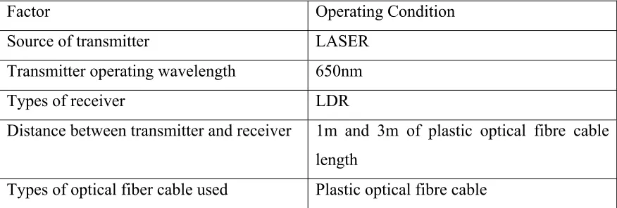
Table 1.1 below lists all the factors and operating conditions considered in this
[image:22.612.109.547.153.301.2]project.
Table 1.1 Parameters and its working operation condition
Factor Operating Condition
Source of transmitter LASER
Transmitter operating wavelength 650nm
Types of receiver LDR
Distance between transmitter and receiver 1m and 3m of plastic optical fibre cable
length
Types of optical fiber cable used Plastic optical fibre cable
Several areas that are being identified or considered that need to be worked and
included in the scope of work are listed as below:
a) The study and understanding of the optical fibre sensor.
b) Identification of the parameters and limiting errors to be considered in
this project.
c) The understanding of the circuit operation (transmitter and receiver) of the
project.
d) The development of a prototype for the project.
e) The analysis of the output data from the project circuit.
f) Finally to conduct and verify the functionality of the system.
1.5 METHODOLOGY
One of the most important aspects in undertaking a project is the methodology. It
laid down the foundation and the execution of the process will be carried out as
scheduled. The progress of the project is constantly checked and reviewed to ensure that
6
as planned. It will start from the beginning where the initial idea is proposed, up till the
end of the project where outcomes as expected are obtained. The methods and processes
involved are shown as below:
1. Project choosing
2. Project planning
3. Literature review
4. Circuit design
5. Hardware development
6. Data analysis
8. Preparation and presentation of technical report
1.6 REPORT STRUCTURE
The thesis is written to record what transpired from the initial form starting with
the idea generated to overcome a problem, the concepts applied, the methods applied to
implement the design, testing, analyzing and develop the product of the project itself.
The thesis consists of five chapters, each chapter covering each aspect of the project
implementation.
Chapter 1 introduces the idea of the project containing the introduction of the
project, the project’s objectives, the problem statement, the scope of work and the
summary of methodology.
Chapter 2 consists of the literature review that covers both the PSM 1 and PSM
II work. The theoretical principles and various applications and concepts are
considered. The major aspect on the various methods and applications in vibration
monitoring system are included for comparison and implementation of the project. This
7
Chapter 3 consists of the project methodology. This chapter deals with the
activities carried out during the development of the project, starting from choosing the
project, project planning and hardware development that form the major bulk of the
project.
Chapter 4 discusses the results found from the research and literature review. The
improvements of the project are also discussed in this chapter as well as the suggestions
for future development.
Chapter 5 concludes the overall task taken and a summary of the final outcome
regards to the findings which include conclusion, suggestion and recommendation for
the project are included. Problems that were encountered during the progress of the