PLC APPLICATION FOR FLOOD DETECTION AND PROTECTION VIA COMMUNICATION SYSTEM
MOHD AKMAL BIN ZAINAL ABIDIN
This report is submitted in partial fulfillment of the requirements for the award Bachelor of Electronic Engineering (Telecommunication Electronics) with honours.
Faculty of Electronic and Computer Engineering Universiti Teknikal Malaysia Melaka
UNIVERSTI TEKNIKAL MALAYSIA MELAKA
FAKULTI KEJURUTERAAN ELEKTRONIK DAN KEJURUTERAAN KOMPUTER
BORANG PENGESAHAN STATUS LAPORAN
PROJEK SARJANA MUDA II
Tajuk Projek : PLC Application for Flood Detection and Protection via
Communication System
Sesi
Pengajian : 0 7 / 0 8
Saya MOHD AKMAL BIN ZAINAL ABIDIN
(HURUF BESAR)
mengaku membenarkan Laporan Projek Sarjana Muda ini disimpan di Perpustakaan dengan syarat-syarat kegunaan seperti berikut:
1. Laporan adalah hakmilik Universiti Teknikal Malaysia Melaka.
2. Perpustakaan dibenarkan membuat salinan untuk tujuan pengajian sahaja.
3. Perpustakaan dibenarkan membuat salinan laporan ini sebagai bahan pertukaran antara institusi pengajian tinggi.
4. Sila tandakan ( √ ) :
SULIT* *(Mengandungi maklumat yang berdarjah keselamatan atau kepentingan Malaysia seperti yang termaktub di dalam AKTA RAHSIA RASMI 1972)
TERHAD** **(Mengandungi maklumat terhad yang telah ditentukan oleh organisasi/badan di mana penyelidikan dijalankan)
TIDAK TERHAD
Disahkan oleh:
__________________________ ___________________________________ (TANDATANGAN PENULIS) (COP DAN TANDATANGAN PENYELIA)
iii
“I hereby declare that this report is the result of my own work except for the quotes as cited in the reference.”
Signature :
iv
“I hereby declare that I have read this report and in my opinion this report is sufficient in terms of the scope and quality for the award of Bachelor of Electronic
Engineering (Telecommunication Electronics) with honours.”
Signature :
v
ACKNOWLEDGEMENTS
With the name of Allah, The Most Gracious and Merciful. Praise to Allah Almighty for giving me the will and strength to go through the industrial training and for giving me opportunity to complete this Final Year Project report successfully.
First and foremost, I would like to express my deepest gratitude and appreciation to my supervisor, Madam Noor Shahida Bt Mohd Kasim for his guidance, advices, supervision and encouragement in making this report. The valuable and useful ideas that he had shared with me during the Final Year Project are very much appreciated.
Secondly, my thanks go to my family for their helps and supports along doing this project. Special thanks also to my friends for their helps and supports in producing this report.
vi
ABSTRAK
Banjir adalah bencana yang paling kerap berlaku di Malaysia. Bencana ini mengakibatkan kehilangan dalam bentuk harta benda dan nyawa. Sebagai tindak balas prihatin terhadap bencana ini, sebuah prototaip untuk mengesan dan mencegah bencana ini telah direka. Sistem ini merangkumi sistem amaran dan pencegahan. Apabila banjir berlaku, litar pengesan air akan mengesan paras air dan menghantar isyarat kepada “Programmable Logic Control (PLC)” yang bertindak sebagai pengawal utama. “Programmable Logic Control” akan mengawal setiap bahagian mengenai sistem ini. Isyarat daripada pengesan paras air akan di proses oleh
“Programmable Logic Control” dan seterusnya menghantar arahan tersebut untuk
menghidupkan pam air. Sekiranya paras air meningkat kepada paras dua dan paras tiga, “Programmable Logic Control” akan mengaktifkan siren dan juga telefon bimbit di mana dalam projek ini telefon bimbit berfungsi untuk membuat panggilan. Hasil daripada projek ini menunjukkan sistem ini berjaya untuk menghidupkan pam air dan mengaktifkan siren dan juga telefon bimbit sekiranya paras air meningkat.
vii
ABSTRACT
Flood is the most frequent disaster that occurs in Malaysia. This type of disaster causes a lot of damage in term of property and life. In the response to this harmful disaster, the flood detection and protection system is designed. The system consists of warning and protection system. When flood occurs, the water lever sensors sense the water level and send the information to Programmable Logic Controller (PLC) as input variable. PLC as a main control board that control each parts of the flood detection and protection system. Information from water level sensors is processed by PLC and send command signal to the actuator to open the water gate. If flood level continuously increase and reaches level two and level three, the PLC will activate the siren and mobile phone. Where, in this project the mobile phone only has a function for making a dialing. The experimental results show that the flood detection and protection system success to open the water pump and active the siren and mobile phone as soon as the flood level increase.
Keyword: Programmable Logic Control (PLC), Water Sensor, Mobile Phone, Siren.
viii
TABLE OF CONTENT
CHAPTER TITLE PAGE
CHAPTER I INTRODUCTION 1
1.1 Project Overview 1
1.2 Problem Statement 2
1.3 Project Objective 2
1.4 Project Scopes 3
1.5 Project Requirement 3
1.6 Expected Result 4
CHAPTER II LITERATURE REVIEW 6
2.1 Introduction 6
2.2 History about PLC 7
2.3 PLC Structure 8
2.3.1 Central Processing Unit 10 2.3.2 The Input/ Output System 10
2.4 PLC Programming 11
2.4.1 Ladder Logic Structure 11
2.5 Water Pump 13
2.6 Sensor 13
2.7 Alarm Unit (Siren) 15
ix
CHAPTER III METHODOLOGY 18
3.1 Project Overview 18
3.2 General Block Diagram 19
3.3 Project Implementation 19
3.4 Experiment Design 23
3.4.1 Experiment Setup 23
3.5 Project Flow Chart 24
3.6 Hardware Design 25
3.6.1 Flood Level Detector Unit and Power
Supply 26
3.6.2 PLC Unit System 27
3.6.3 24VAC/DC Relays 28
3.6.4 Mobile Phone Unit 29 3.6.5 Alarm Unit (Siren) 30
3.7 Software 30
3.7.1 Cx-Programmer 30
3.8 Model Structure 32
CHAPTER IV RESULTS AND ANALYSIS 34
4.1 Introduction 34
4.2 PLC Program 34
4.3 Results 36
4.4 Analysis 41
4.4.1 Simulation from Cx-Programmer and
PLC training kit 41
4.4.2 Simulation using hardware 46
4.5 Prototype of the Project 47
CHAPTER V CONCLUSION AND RECOMMENDATION 48
x
5.2 Recommendation 49
REFFERENCES 50
xi
LIST OF TABLE
TABLE TITLE PAGE
1.1 The Listed of Project Requirement 4
2.1 Specification about NOKIA 1110 16
4.1 Vin and Vout of Voltage Regulator Circuit 37
4.2 Value for Voltage and Current of Water Level Circuit 38
4.3 Functioning of Relay for Each Level 39
xii
LIST OF FIGURES
FIGURE TITLE PAGE
2.1 PLC Architecture 8
2.2 Typical Modular PLC Systems 9
2.3 The Input/ Output System 10
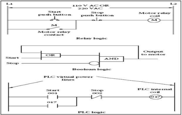
2.4 Figure of Three Types Logic Representation 12
2.5 Aquarium Water Pump 13
2.6 Example of Water Level Detector Sold in Market 14
2.7 Alarm Unit 15
2.8(a) Structure inside the NOKIA 1110 17
2.8(b) Structure inside the NOKIA 1110 17
3.1 General Block Diagram of the project 19
3.2 Flow chart for PSM 1 activities sequence 20 3.3 Implementations of the project for PSM 2 21
3.4 Experiment setup 23
3.5 Flow chart about the system process 25
3.6 General concept of hardware part in the prototype 26
3.7 Show the Water Level Sensor Circuit 27
3.8 12V Power Supply Circuit 27
3.9 Shows the Example of PLC Unit 28
3.10 Show the 24VAC/DC Relays 28
3.11(a) Block Diagram of Mobile Phone Unit 29
3.11(b) NOKIA 1110 Mobile Phone Model 29
3.12 12V Alarm Unit System 30
xiii
3.14 Example of Ladder Diagram 32
3.15(a) Shows the Model Structure of the Project 32 3.15(b) Shows the Model Structure of the Project 33
4.1 Ladder Diagram 35
4.2 Supply Converted from 24V to 12 37
4.3 Three Level of Water Sensor 38
4.4 Relay Connected to Output Devices 39
4.5 Level 1 41
4.6 Level 2 42
4.7 Level 2 (Dialing) 43
4.8 Level 3 44
4.9 Mnemonic code 45
1
CHAPTER I
INTRODUCTION
1.1 Project Overview
2
1.2 Problem Statement
Flood in Malaysia are regular natural disaster which happen nearly every year during the monsoon season. Given Malaysia’s geographical location, most floods that occur are a natural result of cyclical monsoon during the tropical wet season that are characteristic by heavy and regular rainfall. That is the major cause of flooding in Malaysia. Other than that, this flood problem is probability occur to residents whose lives at flooding area [2]. In fact, it is become dangerous to whole resident in the area especially to children and sometime cause death [3]. Besides, it will cause big detriment such as assets destroyed, maintenance cost for electrical equipment and so on [3]. It is also contribute traffic jam for closing the main road where the flood reached at high level [4].
Nowadays, many effort and method has been taken to solve this flood problem such as Project SMART in Kuala Lumpur [5], “Pelan Induk Tebatan Banjir (PITB)”[5] and so on. This effort is good to overcome this flood problem to protect death, detriment and many more when the wet season is coming. So to avoid this problem, this project will do to detect the flood level and prevent it from becomes worst. The project title is “PLC Application for Flood Detection and Protection via Communication System” which it is combination of PLC and communication systems.
1.3 Project Objective
This project is done to achieve the following objectives:
i. To produce a water pump system using PLCs.
ii. To send warning signal to the police station using dialing technique. iii. To detect flood level using water level sensor.
iv. To give warning signal to all resident using a loud siren through a speaker.
3
1.4 Project Scopes
The project scope is to detect and protect the disaster problems to all residents whose lives at lower area and beside a river. The purpose of this project is to use the PLCs as the main controller to control the water pump. In this project, water pump is used to flow out the flood through the underground conduit or pipe to the stagnant area such as flood stagnant reservoir. The water level sensor gives signal of the flood level at the control area. There are three levels, which is level 1 for safety condition, level two for careful condition and level three for dangerous condition.
In this project, mobile phone is applied to make a dialing to another phone where at placed in police station that has been setting into the mobile phone memory. When the PLC receive signal from water level sensor and it sense as a second level, PLC active the mobile phone. Then if water level increase into dangerous level, PLC will active the siren to giving warning to people.
1.5 Project Requirement
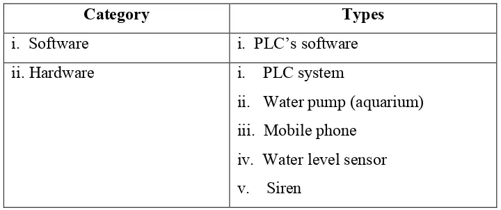
To build this project, the combination of software and hardware are required. There are the importance parts to make the project successful operate. The listed of project requirement are shows in Table 1.1 below:
Table 1.1: The listed of project requirement.
Category Types
i. Software i. PLC’s software ii. Hardware i. PLC system
ii. Water pump (aquarium) iii. Mobile phone
4
1.6 Expected Result
When the flood coming to attack one area, especially for residents whose lives at lower area and beside a river, the project will be able to detect it instantly and effectively. Furthermore, the detection system is also reliable in term the alertness and able to distinguish hoax. That is because, this system will be built at suitable spot and it will control and surveyed.
Another expected result from this project is, the system will operate systematically after the detection of the flood. After it detect, the system will active the water gate to throw out the flood. Furthermore, this system is a efficiency detected the flood level and then automatically connect to the mobile phone and make the dialing to alert and inform the authority exactly what condition in that area. The alarm system also active and will emit a loud siren through a speaker to alert all the resident area where the flood reached at dangerous level.
6
CHAPTER II
LITERATURE REVIEW
2.1 Introduction
A programmable logic controller (PLC) is an industrially hardened computer-based unit that performs discrete or continuous control functions in a variety of processing plant and factory environments. Originally intended as relay replacement equipment for the automotive industry, the PLC is now used in virtually every industry imaginable. Though they were commonly referred to as PCs before 1980, PLC became the accepted abbreviation for programmable logic controllers, as the term “PC” became synonymous with personal computers in recent decades [7].
7
that provides insight on how to use available programming features. Of course, familiarity with one brand of PLC generally helps the engineer learn to use other brands quickly.
2.2 History About PLC
Bedford Associates, the forerunner of Modicon, designed the first PLC in 1968 for the Hydramatic Division of General Motors Corporation to eliminate costly scrapping of assembly line relays during model changeovers and to replace unreliable electromechanical relays. The objectives of the program were to [7]:
i. Extend the advantages of static circuits to 90% of the machines in the plant. ii. Reduce machine downtime related to controls problems.
iii. Provide for future expansion.
iv. Include full logic capabilities, except for data reduction functions.
Richard Morley, a Bedford engineer, is credited with the original PLC design and the creation of ladder logic programming. Morley says the diagrams on which ladder logic is based, however, probably originated in Germany years before to describe relay circuitry. Describing the technology of the day, Morley explains:
8
2.3 PLC Structures
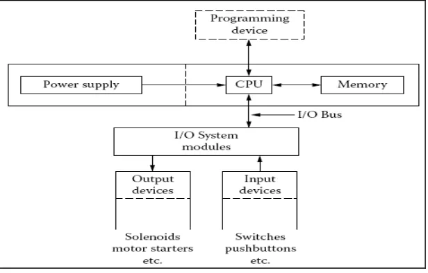
The hardware of a PLC consists of a microprocessor based CPU, a memory, input and output ports where signals can be received such as from switches and sensors, and sent to actuators, for example to motors or valves. A PLC is equipped with an operating system that allows to load and run programs and perform self-checks. Traditionally, the PLC operating system must respond to interrupts and must be real time. In Figure 2.1 illustrate that, the basic of PLC architecture where consist CPU, power supply, memory, I/O system and output and input devices [7].
Figure 2.1: PLC Architecture.
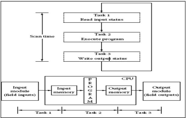
A PLC is a sequential device that performs one task after another. Figure 2.2 shows how a conventional PLC system operates. There are three major tasks of a PLC perform, in the following order:
i. Task 1: Read inputs. PLC checks status of its inputs to see if they are on or off and updates its memory with their current value.
ii. Task 2: Program execution. PLC executes program instructions one by one sequentially and stores the results of program execution in the memory for use later in task 3.
9
After PLC executes task 3 it goes back to execute task 1 again. The total time taken by a PLC to perform these three tasks is called the PLC scan time. Scan time depends on CPU clock speed, user program length, and number of I/O. Typically scan time is in milliseconds. The smaller scan time, the faster the updates of the I/O and the program execution [8]. Figure 2.2 below shows the typical modular of PLC system.
Figure 2.2: Typical Modular PLC Systems.
2.3.1 Central Processing Unit
The central processing unit (CPU) is the part of a programmable controller that retrieves, decodes, stores, and processes information. It also executes the control program stored in the PLCs memory. In essence, the CPU is the brains of a programmable controller. It functions much the same way the CPU of a regular computer does, except that it uses special instructions and coding to perform its functions. The CPU has three parts:
10
The processor is the section of the CPU that codes, decodes, and computes data. The memory system is the section of the CPU that stores both the control program and data from the equipment connected to the PLC. The power supply is the section that provides the PLC with the voltage and current it needs to operate [9].
2.3.2 The Input/ Output System
The input/output (I/O) system is the section of a PLC to which all of the field devices are connected. If the CPU can be thought of as the brains of a PLC, then the I/O system can be thought of as the arms and legs [9]. Figure 2.3 below reveal the Input/ Output system in PLC.
Figure 2.3: The Input/ Output System.
The I/O system is an actual physically carries out the control commands from the program stored in the PLCs memory. The I/O system consists of two main parts:
i. the rack ii. I/O modules
11
and the PLC. When set up properly, each I/O module is both securely wired to its corresponding field devices and securely installed in a slot in the rack. This creates the physical connection between the field equipment and the PLC. In some small PLCs, the rack and the I/O modules come pre-packaged as one unit. All of the field devices connected to a PLC can be classified in one of two categories:
i. Inputs. ii. Outputs.
Inputs are devices that supply a signal/data to a PLC. Typical examples of inputs are push buttons, switches, and measurement devices. Outputs are devices that await a signal/data from the PLC to perform their control functions. Lights, horns, motors, and valves are all good examples of output devices [9].
2.4 PLC Programming
Ladder logic is one of the most popular and widely used programming languages by electricians and programmers, since it emulates the old relay-based ladder logic structure [8].
2.4.1 Ladder Logic Structure
12
the stop pushbutton is pressed, the stop pushbutton’s contact opens, the current path to the relay is opened, the relay gets de-energized, and the relay contact opens. The motor runs as long as the motor relay stays energized. In Boolean logic, the start pushbutton and motor relay contact are represented as inputs to the OR logic block, output of the OR logic block and stop pushbutton are represented as inputs to the AND logic block, and motor relay coil is represented as output of the AND logic block. Normally closed stop pushbutton is shown by inverting the stop input (logical 1). When the start pushbutton is pressed (logical 1), output of the OR block becomes logical 1. With both inputs of the AND block being logical 1, output of the AND block becomes logical 1 and turns the motor relay on. Status of motor relay is fed back to the OR block to keep its output on. Motor relay turns off as soon as the stop button is pressed. In PLC ladder logic, two vertical lines represent virtual power lines, and the actual electrical current is replaced by logical path. A horizontal line represents a logical rung Inputs are shown near the left vertical line and outputs are shown near the right vertical line on a rung. When the inputs have logical 1 or TRUE state, logical path to the outputs completes, and outputs get logical 1 or TRUE state [8]. Figure 2.4 below shows the three types logic can be represented which is in Relay logic, Boolean logic and PLC logic.