UNIVERSITI TEKNIKAL MALAYSIA MELAKA
ENHANCEMENT OF CONTROL SYSTEM USING HMI FOR
MAP204
This report submitted in accordance with requirement of the Universiti Teknikal Malaysia Melaka (UTeM) for the Bachelor’s Degree in Electronics Engineering
Technology (Industrial Electronics) (Hons.) By
MUHAMMAD SYUKRI B MD SALLEH
B071210156
911031-01-6281
UNIVERSITI TEKNIKAL MALAYSIA MELAKA
BORANG PENGESAHAN STATUS LAPORAN PROJEK SARJANA MUDA
TAJUK: ENHANCEMENT OF CONTROL SYSTEM USING HMI FOR MAP204
SESI PENGAJIAN: 2015/16 Semester 1
Saya MUHAMMAD SYUKRI B MD SALLEH
mengaku membenarkan Laporan PSM ini disimpan di Perpustakaan Universiti Teknikal Malaysia Melaka (UTeM) dengan syarat-syarat kegunaan seperti berikut:
1. Laporan PSM adalah hak milik Universiti Teknikal Malaysia Melaka dan penulis. 2. Perpustakaan Universiti Teknikal Malaysia Melaka dibenarkan membuat salinan
untuk tujuan pengajian sahaja dengan izin penulis.
3. Perpustakaan dibenarkan membuat salinan laporan PSM ini sebagai bahan pertukaran antara institusi pengajian tinggi.
4. **Sila tandakan ( )
SULIT
TERHAD
TIDAK TERHAD
(Mengandungi maklumat yang berdarjah keselamatan atau kepentingan Malaysia sebagaimana yang termaktub dalam AKTA RAHSIA RASMI 1972)
(Mengandungi maklumat TERHAD yang telah ditentukan oleh organisasi/badan di mana penyelidikan dijalankan)
Alamat Tetap:
ii
DECLARATION
I hereby, declared this report entitled “Enhancement of control system using HMI for MAP 204” is the results of my own research except as cited in references.
Signature : ……….
Author’s Name : MUHAMMAD SYUKRI B MD SALLEH
iii
APPROVAL
This report submitted in to the Faculty of Engineering Technology of UTeM as a partial fulfillment of the requirements for the degree of Bachelor Degree of Engineering Technology Electronic Industry Hons. The member of the supervisory is as follow:
………
iv
ABSTRAK
v
ABSTRACT
vi
DEDICATION
A special thank you to my parent Md Salleh B Mahadi and Jarilah Binti Atan
My supervisors
vii
ACKNOWLEGMENT
I wish to express sincere appreciation to Universiti Teknikal Malaysia Melaka (UTeM) for giving me a chance to further my study in Bachelor’s Degree in Electronics Engineering Technology (Industrial Electronics).
Despite of that, I would like to take this opportunity to express my profoundest gratitude and deepest regards to all those who gave me the possibility to successfully complete this final year project (FYP). I am deeply indebted to my Project Supervisor En Ahmad Nizam Bin Mohd Jahari @ Johari and En Shamsul Fakhar Bin Abd Gani and I wish to express a million thanks fo her exemplary guidance, monitoring and constant encouragement throughout the development of the project.
viii
Acknowledgement vii
ix
2.1 MAP 204 6-7
2.1.1 MAP 204 Components 7-9
2.2 GRAFCET 9
2.2.1 GRAFCET and Its Elements 10-11
2.3 Programmable Logic Controller (PLC) 11
x
3.5 Troubleshooting 25
3.6 Determine the suitable sensor that can be integrate 26
3.7 Designing HMI 26
4.2.1 Control Circuit Ladder Diagram 34
4.2.2 Power Circuit Ladder Diagram 34
4.2.3 Timer Circuit Ladder Diagram 35
xi
4.5.2 Ladder Diagram 40-41
4.5.3 Sensor Detect Object and Indicator Lamp 41
4.5.4 HMI of MAP 204 41-42
CHAPTER 5 : CONCLUSION AND FUTURE WORK 43
5.1 Summary of Research 43
5.2 Achievement of Research Objectives 44
5.3 Significance of Project 44
5.4 The Problem That Faced During Develop Project 44
5.5 Future Work 44-45
APPENDIX 46-58
xii
LIST OF TABLE
2.3.1 Differentiation between PLC and Hard Wire Logic. 12
2.5.2 The Thru Beam Sensing Modes 19-20
4.1 The Table of sequence, output and transition. 32
4.1.2 The Table of GRAFCET Element 33
xiii
LIST OF FIGURES
CHAPTER 1 : INTRODUTION
1.1 Illustration Block Diagram of Project 2
CHAPTER 2 : LITERATURE REVIEW
xiv
3.7.2.a Bit Button Property and address for the button 27
CHAPTER 4 : RESULT AND DATA ANALYSIS
4.2.1 An example control circuit ladder diagram 34
4.2.2 show example of power circuit ladder diagram. 35
4.2.3 – show the example of timer circuit ladder diagram. 35
4.2.4 – example of work bit ladder diagram 35
xv
LIST OF ABBREVIATIONS, SYMBOLS AND
NOMENCLATURE
HMI : Human Machine Interface PLC : Programmable Logic Controller
GRAFCET : GRAphe Fonctionnel de Commande Etape Transition.
NO : Normally Open
NC : Normally Closed
PSM : Projek Sarjana Muda FYP : Final Year Project.
1
CHAPTER 1
INTRODUCTION
In this chapter will discuss about the introduction of MAP-204 and explanation about the technique that use to upgrade the controlling method of the MAP-204 by using CX-Programmer. The general ideas on his project also have been given in the block diagram figure. Besides that objectives, problem statement and the report structure is attached as well.
1.1 Project Briefing.
2
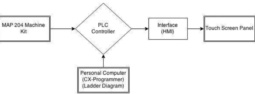
First of all, the CX-Programmer is software that used to build the ladder diagram or the PLC programming. The function of programming code is to make the movement of system MAP 204 following the sequence of the MAP 204 system. The HMI of MAP 204 will be built by the NB-Designer software. This front panel provides user interface which is used to operate the system with multiple options such as start or stop operation, auto or manual operation and reset operation.
Figure 1.1 Illustration Block Diagram of Project
1.2 Problem Statement
3
The MAP – 204 has only one method input is using the push button. Two push button being use. First push button is about to start system and second push button is about to stop the system of the MAP – 204 machine.
1.3 Project Objectives
The objective of this project is:
1. Identify and enhance the new controlling method of MAP 204 2. Design and develop the HMI for the MAP 204
3. Implement the designed HMI into the MAP 204
1.4 Project Scope.
1.4.1 Research about GRAFCET of the MAP 204.
- Firstly study about the GRAFCET. The GRAFCET is a one of the design technique to build the ladder diagram. Obtain the MAP 204 sequence and determined the sensor that will activate sequence.
1.4.2 Build the ladder diagram of the MAP 204.
- From the GRAFCET the ladder diagram can be built. The ladder diagram will construct in CX-Programmer software. Four type the ladder diagram can be built:
4
o Power Circuit o Timer Circuit o Work Bit Circuit
1.4.3 Doing some research about the suitable sensor to be implementing on the MAP 204.
- The sensor is use to detect the presence of the part. Do some research about what a most suitable sensor type that can be implement on the MAP 204. Study about how to integrate the sensor with MAP 204 station.
1.4.4 Design the HMI that can be integrated with the MAP 204 station.
- Using the CX-Designer software to design the layout of the touch screen panel for MAP 204 station.
1.4.5 Implementation on the MAP 204.
5
1.5 Report Structure.
This thesis is a document report of the ideas generated and concepts applied, the activities performed and the final product of this project product produced. The thesis consists of three chapters and each chapter is described as below:
Chapter 1, the introduction of MAP-204 and explanation about the technique that use to upgrade the controlling method of the MAP-204 by using CX-Programmer. The general ideas on his project also have been given in the block diagram figure. Besides that objectives, problem statement and the report structure is attached as well.
Chapter 2, discussing about the literature review. From the literature review, will be explanation about an analysis of each phase in this project. The explanation will include about the dimension, operation and specification of the equipment and part.
6
CHAPTER 2
INTRODUCTION
This chapter will be discussing about the literature review. From the literature review, will be explanation about an analysis of each phase in this project. The explanation will include about the dimension, operation and specification of the equipment and part.
2.1 MAP Series (MAP 204).
The MAP-204 is a horizontal roto-linear handling device with external gripper. The MAP-204 consists of a roto-linear handling device fitted with an external gripper which moves a part from one position to another [1]
7
Figure 2.1 Figure of MAP 204
2.1.1 MAP 204 components.
1) Roto-linear manipulator device.
This roto-linear device can move to 4 directions. First direction is from angle until . This device also can move upward and downward.
8 2) An external gripper.
An external gripper is fitted to the roto-linear manipulator. The function is about to hold the part during the transfer from one place to the other place.
Figure 2.1.1.b An External Gripper
3) Part and part holder.
a. The part is a part that being hold and move by the gripper. b. The part holder is about the place to put the part.