ISSN: 1693-6930
accredited by DGHE (DIKTI), Decree No: 51/Dikti/Kep/2010 327
Induction Heating Process Design Using COMSOL
®Multiphysics Software
Didi Istardi*1, Andy Triwinarko2
1
Department of Electrical Engineering, Batam Polytechnics, Batam, Indonesia Parkway st, Batam Centre, Batam, Indonesia, +62-778-469856 2
Department of Informatics, Batam Polytechnics, Batam, Indonesia Parkway st, Batam Centre, Batam, Indonesia, +62-778-469856
e-mail: [email protected]*1, [email protected]
Abstrak
Pemanasan induksi merupakan sebuah proses pemanasan yang ramah lingkungan karena proses pemanasannya yang tidak saling bersentuhan antar medianya. Ada banyak jenis pemanasan induksi yang digunakan untuk aplikasi rumah tangga, tapi ini masih merupakan teknologi yang baru di Indonesia. Permasalahan yang menarik dalam mendesain pemanasan induksi yaitu masalah effisiensi dari pemakaian energi dan pemilihan dari material plat. Perangkat lunak COMSOL® Multiphysics digunakan untuk mensimulasikan dan mempresentasikan dari proses pemanasan induksi ini. Perangkat lunak ini dapat digunakan untuk mendesain pemanasan induksi yang mempunyai effisiensi yang bagus. Dalam makalah ini parameter-parameter yang mempengaruhi dalam desain proses pemanasan induksi akan disimulasikan dan dianalisa seperti pengaruh dari lebar plat induktor, jarak antar induktor, dan jenis dari material plat. Berdasarkan dari simulasikan ini terlihat bahwa sebuah desain yang baik dari pemanasan induksi harus mempunyai lebar dan jarak antar induktor yang pendek dan menggunakan plat material dari silicon carbide dengan menggunakan pengontrolan frekuensi tinggi.
Kata kunci: COMSOL, plat penghantar, analisa efisiensi, pemanasan induksi
Abstract
Induction heating is clean environmental heating process due to a non-contact heating process. There is lots of the induction heating type that be used in the home appliance but it is still new technology in Indonesia. The main interesting area of the induction heating design is the efficiency of the usage of energy and choice of the plate material. COMSOL® Multiphysics Software can be used to simulate and estimate the induction heating process. Therefore, the software can be used to design the induction heating process that will have a optimum efficiency. The properties of the induction heating design were also simulated and analyzed such as effect of inductor’s width, inductor’s distance, and conductive plate material. The result was shown that the good design of induction heating must have a short width and distance inductor and used silicon carbide as material plate with high frequency controller.
Keywords: COMSOL, conductive plate, efficiency analysis, induction heating
1. Introduction
A green and renewable energy, high cost, and clean environmental are important issues that influenced the technology in home appliances recently such as in stove and water heating. Induction heating is one of the new technologies in home appliance. There are some researches that discussed about induction heating process and implementation due to their clean and no pollution [1]-[5]. A lot of this research focus on experimental and analytical method used finite element method to solve the efficiency of the usage of energy and choice of the plat material that used in induction heating process. According to this reasons, the design of induction heating is simulated and analyzed using COMSOL® Multiphysics software that have a graphical and interactive simulation [6]-[9]. In this paper, the properties of the induction heating are considered such as the effect of frequency, distance of inductor, induction width, and conductive material of inductor or plate.
generated inside the work piece. This can be contrasted with other heating methods where heat is generated in a flame or heating element, which is then applied to the work piece.
A source of high frequency electricity is used to drive a large alternating current through a coil [3]. This coil is known as the work coil. The passage of current through this coil generates a very intense and rapidly changing magnetic field in the space within the work coil. The work piece to be heated is placed within this intense alternating magnetic field [10], [11].
The alternating magnetic field induces a current flow in the conductive work piece. The arrangement of the work coil and the work piece can be thought of as an electrical transformer. The work coil is like the primary where electrical energy is fed in, and the work piece is like a single turn secondary that is short-circuited. This causes tremendous currents to flow through the work piece. These are known as eddy currents.
In addition to this, the high frequency used in induction heating applications gives rise to a phenomenon called skin effect [10]-[12]. This skin effect forces the alternating current to flow in a thin layer towards the surface of the work piece. The skin effect increases the effective resistance of the metal to the passage of the large current. Therefore it greatly increases the heating effect caused by the current induced in the work piece. The principle of induction heating is mainly based on two well-known physical phenomena:
Electromagnetic induction, the energy transfer to the object to be heated occurs by means of electromagnetic induction. It is known that in a loop of conductive material an alternating current is induced, when this loop is placed in an alternating magnetic field. The formula is the following [11] that the change of flux magnetic (
d
φ
) over the change of time (dt):
dt d
E= φ (1)
When the loop is short-circuited, the induced voltage (E) will cause a current to flow that opposes its cause – the alternating magnetic field. This is Faraday - Lenz’s law.
If a ‘massive’ conductor (e.g. a cylinder) is placed in the alternating magnetic field instead of the short circuited loop, than eddy currents (Foucault currents) will be induced in here. The eddy currents heat up the conductor according to the Joule effect
The second phenomena is joule effect, when a current I [A] flows through a conductor with resistance R [Ω], the power P [W] is dissipated in the conductor according to [11].
2 RI
P= (2)
A general characteristic of alternating currents is that they are concentrated on the outside of a conductor. This is called the skin effect. Also the eddy currents, induced in the material to be heated, are the biggest on the outside and diminish towards the centre [13]. So, on the outside most of the heat is generated. The skin effect is characterized by its so-called penetration depth (ߜ). The penetration depth is defined as the thickness of the layer, measured from the outside, in which 87% of the power is developed. The penetration depth can be deduced from Maxwell’s equations. For a cylindrical load with a diameter that is much bigger thanߜ, the formula is as follows:
f
. .µ π
ρ
δ = (3)
Above the Curie temperature µr suddenly drops again to µr=1, which implies a rapid increase of the penetration depth. The current flow in skin effect can be calculated using equation:
δ
refer to current density on skin depth.
The paper is organized as follows: In the next section, the research method of the problem in COMSOL is explained. The section also explains the geometry object and constraint in this simulation. Section III presents results of simulation using COMSOL® Multiphysiscs software and discussion of the results. Finally, the conclusions are made in section IV.
2. Research Method
In this paper, the quantities that want to be computed and analyzed are the effect of the inductor’s width, distance on the efficiency at frequency 50 Hz and 2 kHz, and the material of the plate affects the results. According to this problem, the equations to be solved in the COMSOL Multiphysiscs software will be start with Ampere’s law as seen in,
t
Now assume time-harmonic fields and use the definitions of the potentials,
xA In the 2D in-plane case there are no variations in the z direction, and the electric field is parallel to the z-axis. Therefore, the potential diffenence can write as −∆V/L where ∆V is the potential difference over the distance L. Now simplify these equations to
(
o)
z z zThe mathematical model for heat transfer by conduction is the following version of the heat equation
current through the inductor and can be calculated using the formula:
The value of the second integral is known, because the total current is part of the boundary conditions. However, performing the integration of the FEM solution provides an opportunity to verify that the previous calculations are correct.
The skin depth, that is, the distance where the electromagnetic field has decreased by a factor e−1, is for a good conductor,
f
πµ ρ ωµσ
δ= 2 = (13)
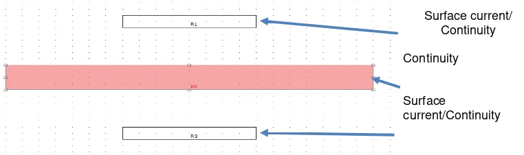
The geometry of this simulation in this paper can be seen in Figure 1. Information written in red refer to the AC Power Electromagnetic (qa) mode, and the ones in green refer to
the Heat Transfer by Conduction (ht) mode. The heat source comes from the resistive heating,
time average (Qav_qa) which is used inside the conductive plate. Material of induction heating
referred to Table 1. Sub domain settings of this simulation can be referred to Table 2 and Table 3.
Figure 1. Object geometry of induction heating
Table 1. Material properties of induction heating
Material Electric
Conductivity (σ)
Permeability (µ) Heat capacity (J/kg.K)
Thermal conductivity
Density (kg/m3)
Aluminum 3.774.107
1 900 160 2700
Copper 5.998.107 1 385 400 8700
Iron 1,12.107 4000 400 76,2 7870
Steel (AISI 4340) 4,032.106 1 475 44,5 7850
Silicon Carbide 1.103
1 1200[ 450*(300/T)0.75
3200
Table 2. Properties of AC Power Electromagnetic (qa)
Settings Sub domain 1, 3-4 Sub domain
Relative permeability (mur) 1 {1,0;0,1} {1,0;0,1} (Copper)
Relative permittivity (epsilonr) 1 1 1 (Copper)
Electric conductivity (sigma) S/m 0 5.998e7[S/m] (Copper)
Table 3. Properties of Heat Transfer by Conduction (ht)
Settings Sub domain 1 Sub domain 2 Sub domain 3,4
Thermal conductivity (k) 0.026 400[W/(m*K)] (Copper) 400[W/(m*K)] (Copper)
Density (rho) 1.293 8700[kg/m^3] (Copper) 8700[kg/m^3] (Copper)
Heat capacity at constant pressure (C) 1.01e3 385[J/(kg*K)] (Copper) 385[J/(kg*K)] (Copper)
Heat source (Q) 0 Qav_qa 0
3. Results and Discussion 3.1 Inductor’s Width
In this part of the paper, the inductor’s width has been changed, for two different frequencies 50 Hz and 2 kHz. First of all, the skin effect which has been introduced before should be presented using a practical case and the software COMSOL® Multiphysics. The following example compares the temperature and current density distributions for the same configuration; only the frequency is changed (50 Hz and 2 kHz) as can be seen in Figure 2.
Surface current/ Continuity
Continuity
Surface
current/Continuity
It is easy to see how the skin effect affects the current distribution. With a higher frequency, the current density is increased near the boundary, and the different penetration depth (δ) can be calculated in order to quantify this skin effect. From the Figure 2, the skin effect does not effect to the variation of the inductor’s width. Skin effect only depends on frequency, electric conductivity and permeability (equation 3). Based on this equation, the values of skin effect can be seen in Table 4. In the following analyze, the width’s of the inductor has been increased, but the distance between the inductor winding and the conductive plate has been kept constant. The result of simulation can be seen in Table 5.
@ 50 Hz @ 2 kHz
Table 4. Comparison of skin depth
Skin depth(mm)
Frequency
50 Hz 2 kHz
Calculate 3 0.5
Simulation 8 2
Figure 2. Current density distribution in different frequency
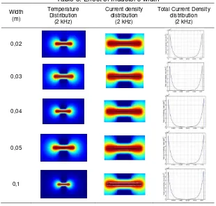
Table 5. Effect of Inductor’s width
Width (m)
Temperature Distribution
(2 kHz)
Current density distribution
(2 kHz)
Total Current Density distribution
(2 kHz)
0,02
0,03
0,04
0,05
0,1
At frequency 2 kHz, the current distribution is not linear anymore (equation 4). The current density is higher near the boundary (skin effect), and it can be seen that the increasing of width amplify this phenomena. The density of the magnetic field wanes as the object gets closer to the center from the surface. According to Faraday’s Law, the current generated on the surface of a conductive object has an inverse relationship with the current on the inducting circuit as described in (equation 4).The current on the surface of the object generates an eddy current.
If an object has conductive properties like iron, additional heat energy is generated due to magnetic hysteresis. The amount of heat energy created by hysteresis is in proportion to the size of the hysteresis. The efficiency can be calculated using equation:
copper
average time) with subdomain in plate material and in Pin in subdomain inductor.
If the inductor’s width changes the current density also will change
A I
Js0= 0 (15)
where the A are area of inductor. So, if area of inductor increases, the current density will be decreased. Therefore, the electromagnetic induces to plate material also reduce and the power in plate material also reduced (Ampere’s Law), and the efficiency will decrease.
If the frequency increase the power will be increase also the efficiency is higher than in lower frequency. It can be illustrate that in high frequency, the ac resistance (Rac) will be higher
than dc resistance (Rdc), it happen due to skin effect phenomena. So, the efficiency can be
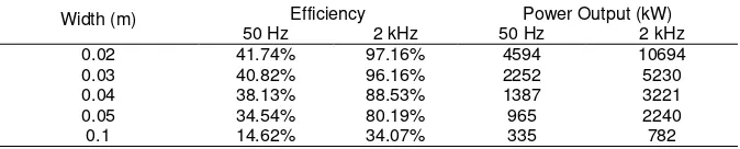
The comparison of efficiency and power output in different width and frequency can be seen in Table 6. Table 6 shown that the penetration depth and the temperature will be varied with the electric conductivity and permeability.
Table 6. Efficiency and power output of induction heating in different frequency
Width (m) Efficiency Power Output (kW)
50 Hz 2 kHz 50 Hz 2 kHz
The distance between inductor and conductive plate also affect the induction heating process, and this mechanism is called proximity effect. If the distance between inductor plate and conductive plate increase, then the strength of the proximity effect will decrease. Due to Faraday’s Law, the eddy current within the conductive plate have an opposite direction to that of the source current of inductor. Therefore, due to proximity effect, the inductor current and the conductive plate eddy current will concentrate in the area facing each other.
For example, at 50 Hz, it can be done by increasing the distance between the inductor and the plate, but the width of the inductor stayed constant. It can be observed that to change the distance between the inductor and the plate, has consequences on the temperature distribution outside the material but not on the skin effect. Actually, the current density is still linear inside the material. However, it can also be noticed that the efficiency has changed.
of the induction heating is affected. It is easy to understand that the heating action is decreased when the distance increases.
Table 7. Maximum current density in conductive plate
Distance of air gaps Maximum Current density [A/m²]
0.03 m 10.107
0.04 m 9.106
0.05 m 8.106
0.06 m 7.106
0.1 m 5.106
3.3 Conductive Plate Material
At last but not least, an interesting study is about the variations of the material of the plate. The following example shows a comparison between copper, iron, steel and silicon carbide as seen in Table 8. It can be shown that the distribution of the current density inside the material is more or less linear, depending on the material used. The current distribution inside the copper or the aluminum are strongly non linear, but it is almost linear if the material used is steel, or even more with silicon carbide. This is related to the electric conductivity. The different values of electric conductivity for each material can be compared as follow: σcu > σAl > σSteel > σSic; so, smaller the value of the electric conductivity is, more linear the current density inside
the material will be.
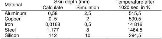
However, there is an exception to this behavior, it is iron. Actually, the material has an unexpected behavior, but this is due to its relative permeability which is much higher than for the other materials. Table 8 shows that the penetration depth and the temperature will be varied with the electric conductivity and permeability.
Table 8. Effect of conductive plate material in induction heating
Material Skin depth (mm) Temperature after 1020 sec, in °K Calculate Simulation
Aluminum 0,58 2,5 515,5
Copper 0, 5 2 590,5
Iron 0,0168 0,5 14 816
Steel 1,177 8 1464,5
Silicon 112 10 294,5
4. Conclusion
This paper has focused on the pre-design of induction heating using COMSOL® Multiphysics software that would be implemented in home appliance (kitchen appliance). The properties of the induction heating has been analyzed and discovered. The variation of the width inductor has no effect on the current density distribution, but it affects the efficiency of the induction heating process. If the width inductor is increased, the efficiency reduced and vice versa. Therefore, the good design of induction heating has a small inductor that also take care about the skin effect that will be happened in high frequency.
In this paper, the distance between inductor and conductive plate also analyzed. For the distance variations, the current density distribution is not effected. The maximum value of The current density is decreased when the distance is increased. If the conductive plate material is changed, variations on the current density distribution have been observed. Actually, if we increase the electric conductivity, the linearity of the distribution is decreased. As a result, the proposed design of the induction heating that be recommended by author are the induction heating that have a short width and distance of inductor and plate material, using silicon carbide, and with high frequency controller.
References
[2] Savia D. J., Induction Heating of Samples in Vacuum Systems. In The Proceeding of the COMSOL Users conference 2007 Grenoble, 2007.
[3] Barragan LA., Navarro D., Acero J, Urriza I, and Burdio J.M, FPGA Implementation of a Switching Frequency Modulation Circuit for EMI Reduction in Resonant Inverters for Induction Heating Appliances, IEEE Transactions on Industrial Electronics. 2008; 55(1):11-20.
[4] Jankowski, T. A. and Others. Experimental Observation and Numerical Prediction of Induction Heating in Graphite Test Article. In The Proceeding of the COMSOL conference 2009 Boston, 2009.
[5] Fabbri M., Forzan M., Lupi S., Morandi A., and Ribani P.L., Experimental and Numerical Analysis of DC Induction Heating of Aluminum Billets, IEEE Transactions on Magnetics. 2009; 45(1): 192-200. [6] Rivera M.J., López Molina J.A., Trujillo M, Romero-Garcia V., And Berjano E.J., Analytical
Validation of COMSOL Multiphysics for Theoretical Models of Radio Frequency Ablation Including the Hyperbolic Bioheat Transfer Equation, 32nd Annual International Conference of the IEEE EMBS. Buenos Aires. 2010: 3214 – 3217.
[7] Syaifudin A.R.M., Mukhopadhyay S.C., Yu P.L, Electromagnetic Field Computation using COMSOL Multiphysics to Evaluate the Performance of Novel Interdigital Sensors, Applied Electromagnetics Conference (AEMC). Kolkata. 2009:1-4.
[8] Renmin Li, Lei Fang, Songyu Liu , Hydrogeologic Parameters Inverse Analysis Based on Pumping Test by Comsol Multiphysics and Matlab, 2010 International Conference On Computer Design And Appliations. Hebei. 2010; 2: 160-163.
[9] Ernest, R., Perrier, D., Feigenblum, J., and Hemous, R. 3D Inductive Phenomena Modelling. In The Proceeding of the COMSOL Users conference 2006, Paris, 2006.
[10] Rudnev V. I. Handbook of Induction Heating. Marcel Dekker Inc, 2003.
[11] Leinhard IV, J H and Leinhard V, J.H. A Heat Transfer Textbook, Massacushetts, 2006.
[12] Jungwirth, M. and Hofinger, D. 2007. Multiphysics Modelling of High-Frequency Inductive Device. The Proceeding of the COMSOL Users conference 2007 Grenoble, 2007.