Bandung 40132 Kampus IV : JL.DIPATI UKUR 114 TELP (022) 2506553, 2508412 Bandung 40132
STUDENT BIO DATA PERSIONAL DETAILS:
Student ID : 10511657
Name : Patrick Nolye
Place/Date of Birth : Papua New Guinea, 3rd-March-1989
Gender : Male
Semester : 8
Educational Achievement : Degree Holder
GPA : 3.44
House Address : Jl Sekeloa Timur, RT 05/RW 03, Bandung 40141
E-mail : [email protected]
Telephone No :+6281312425285
FAMILY DATA:
Father Name : Michael Nolye
Mother Name : Merilyn Nolye
Parents Home Address : South West Air, P.O. Box, 71 Mendi, S.H.P, P.N.G. Parents Telephone : +67571059762
Parents Occupation : Engineer/House Wife
Modeling Language Reference Manual”, 2nd ed, Addison Wesley Longman, Inc: Canada, 1999, [4, p.43].
2. Jian Wang. Object-Oriented Analysis Methodology. School of Business Administration, University of Missouri-ST. Lous, 2001.
3. Juris Kelley (2002). Management and Optimizing Team Collaboration, Xulon Press.
4. Lawrence R. Frey, Car H. Botan, Paul G. Friedman, and Gary L. Kreps. An Introduction to Research Methods. Prentice Hall College Div, 1991
5. Seema, SonaMalhotra 278. International Journal of Advances in Computing and Information Technology. SE/CSE Department, U.I.E.T. Kurukshetra University.
First of all, I want to thank the almighty God for His constant love and blessings upon my life to come this far. I give all the praises and glory to Him alone as I am able to complete my degree program on time. My thesis title is “Fr. Peter Secondary School Management System”.
In this time, the writer would like to thank everyone that may have been helpful and supportive in any means in my studies and to get this thesis done on time. They are:
1. Dr. Ir. Eddy Suryanto Soegoto, M.Sc, Rektor (Chancellor), Universitas Komputer Indonesia.
2. Prof. Dr. Umi Narimawati, Dra., SE., M.Si, International Program Director, Universitas Komputer Indonesia.
3. Prof. Dr. H. Denny Kurniadie. Ir., M.Sc. Dean of Faculty of Engineering & Computer Science, Universitas Komputer Indonesia.
4. Ibu Citra Noviyasari S.Si.,M.T, Head of Information System Department, Universitas Komputer Indonesia.
5. Ibu Imelda, ST. MT., My Guardian Lecturer, for her guidance, support and her continuous enthusiasm and encouragement throughout my thesis.
8. My friends like: Brother Barton, Abud, Pebrina Gultom, Espren Sitorus, and others who have been so helpful and supportive.
9. The very special person in my life, Kathleen A.K. Jahamou, for her care and love upon my life.
10. Furthermore, to my most encouraging and caring dad (Michael Nolye), mum (Merilyn), sister (Emmy), Tap’s and J.Onimnga’s family for their support through prayer and their hopes in me. Also not forgetting those that were financially supportive especially uncle Sam and aunty Zean and others throughout my studies.
The writer would also like to apologize if not mentioning any names in particular who may have been in one way or the other being helpful.
14
2.1. Information
Wiig (1993) – He has suggested that the information as, “facts organized to describe a situation or condition. According to Juris and Kelley (2002) – They have suggested the “information is much more refined data that has evolved to the point of being useful for some form of analysis”. From these two sources, Information can be defined as: “data that has beenprocessedin such a way as to bemeaningfulto the person who receives it.”
2.1.1. Qualities of Good Information
According to Rush (Free-Education Forum-online), there are several qualities of a good information. These are as follows:
Accurate
There should not be any false facts in the information given and the data and the data should add up to the final decision being made.
Accessible
Complete
The information should be complete to the level that the user needs not require additional methods or systems to understand or use the information.
Brief
The information should not contain unwanted or facts or lengthy descriptions of facts. This factor is dependent on the level of users within the organizations.
Secure
The information should not be contaminated or easily accessible to unauthorized persons.
Timely
The information should be received on time and should be available for updating on a timely basis.
Up to Date
The information should be based on facts which are current and most recently updated data.
Rare
The information should be available to only a limited number of users otherwise the value of the information will diminish.
2.2. System
1. A group of interdependent items that interact regularly to perform a task.
2. An established or organized procedure; a method.
Therefore, in computer, a system is one that is able to take a set of inputs, process them and create a set of outputs. This is done by combination of hardware and software.
In a system, network of components work towards a single objective, if there is lack of co-ordination among components, it leads to counterproductive results
2.2.1. Features of a System
A system may have following features:
1. Adaptability: some systems are adaptive to the exterior environment, while some systems are non-adaptive to the external environment.
2. Limitation: every system has pre-defined limits or boundaries within which it operates. This limits or boundaries can be defined by law or current state of technology.
2.2.2. Components of a System
1. Input elements
The information entered into a system. For instance raw data input to the computer system.
2. Process
Any specific treatment defined in the system to be performed on the data entered into the system, for instance, computation, analysis, application of any model.
3. Output elements
The results given by the system after the process has been performed on the data being input to the system.
4. Control mechanism
Every system is expected to generate some sort of standardized output. Hence actual output needs to be compared with what it is supposed to generate. This comparison of actual with expected output is done with the help of control mechanism.
5. Feedback system
Once the control mechanism has been devised, it needs to a reporting mechanism, which should respond with a corrective action, if required.
6. Objectives
2.2.3. Types of System 1. Open System
An open system is one that interacts with its environment and thus exchange information, material, or energy with the environment, including random and undefined inputs. Open systems are adaptive in nature, as they tend to react with the environment in such a way, so as to favor their continued existence. Such systems are „self organizing’, in the sense that they change their organisation in response to changing conditions.
2. Closed System
closed system is one, which does not interact with its environment. Such systems in business world, are rare, but relatively closed systems are common. Thus, the systems that are relatively isolated from the environment but not completely closed, are termed closed system.
3. Open Loop System
In open-loop architecture, business decisions made by management have an impact in the marketplace, and the impact of that decision is measured only indirectly by the company's computer systems.
4. Closed Loop System
2.3. Information Systems
According to Vladimir Zwass (Encylopaedia Britannica), Information System is an integrated set of components for collecting, storing, and processing data and for delivering information, knowledge, and digital products. According to Management Study Guide (managementstudyguide.com), an information system, therefore, can be defined as set of coordinated network of components which act together towards producing, distributing and or processing information. An important factor of computer based information system is precision, which may not apply to other types of systems.
2.3.1. Components of Information System
An information system is essentially made up of five components hardware, software, database, network and people. These five components integrate to perform input, process, output, feedback and control.
1. Hardware consists of input/output device, processor, operating system and media devices.
2. Software consists of various programs and procedures. 3. Database consists of data organized in the required structure.
5. People consist of device operators, network administrators and system specialist.
Information processing consists of input; data process, data storage, output and control. During input stage data instructions are fed to the systems which during process stage are worked upon by software programs and other queries. During output stage, data is presented in structured format and reports.
2.4. Secondary Education
According to Wikipedia, secondary education normally takes place in secondary schools, taking place after primary education and may be followed by higher education or vocational training. In some countries, only primary or basic education is compulsory, but secondary education is included in compulsory education in most countries.
Normally, secondary education lasts for four (4) years and is divided into two cycles: lower (grades 9 and 10) and upper secondary (grades 11 and 12). Students sit two examinations: the School of Certificate Examination at the end of grade 10, and the Higher School Certificate Examination at the end of grade 12.
2.4.1 Terminology
Secondary schools may be called high schools, gymnasia, lyceums, middle schools, sixth-form, sixth-form colleges, vocational schools, or preparatory schools, and the exact meaning of any of these varies between the countries.
2.5. Enrollment
According to Wikipedia, enrollment may refer to the total number of students properly registered and/or attending classes at a school.
2.6. Registration
According to Merriam Webster dictionary, registration refers to the act or process of entering personal (student) information in a system (school) of public records.
2.7. School Fee Ledger
2.8. PHP Programming
PHP is a server-side scripting language designed for web development but also used as a general-purpose programming language. As of January 2013, PHP was installed on more than 240 million websites (39% of those sampled) and 2.1 million web servers. Originally created by Rasmus Lerdorf in 1994, the reference implementation of PHP (powered by the Zend Engine) is now produced by The PHP Group. While PHP originally stood for Personal Home Page, it now stands for PHP: Hypertext Preprocessor, which is a recursive backronym.
2.9. JavaScript
JavaScript is the programming language of HTML and the Web. It is also known as ECMAScript (the untrademarked name used for the standard), It is most commonly used as part of web browsers, whose implementations allow client-side scripts to interact with the user, control the browser, communicate asynchronously, and alter the document content that is displayed. JavaScript (at least the strict subset asm.js is also considered an "assembly language of the web – a compile target of source-to-source compilers – for making client side web applications, using other programming languages, supported by all the major browsers without plug-ins. It is also used in server-side network programming with runtime environments such as Node.js, game development and the creation of desktop and mobile applications.
JavaScript is classified as a prototype-based scripting language with dynamic typing and first-class functions. This mix of features makes it a multi-paradigm language, supporting object-oriented, imperative, and functional programming styles. JavaScript is also used in environments that aren't web-based, such as PDF documents, site-specific browsers, and desktop widgets.
2.10.HTML
of HTML elements consisting of tags enclosed in angle brackets (like <html> ). HTML tags most commonly come in pairs like <h1> and </h1> , although some tags represent empty elements and so are unpaired, for example <img> . The first tag in a pair is the start tag, and the second tag is the end tag (they are also called opening tags and closing tags).
Web browsers can read HTML files and compose them into visible or audible web pages. Browsers do not display the HTML tags and scripts, but use them to interpret the content of the page. HTML describes the structure of a website semantically along with cues for presentation, making it a markup language, rather than a programming language.
HTML elements form the building blocks of all websites. HTML allows images and objects to be embedded and can be used to create interactive forms. It provides a means to create structured documents by denoting structural semantics for text such as headings, paragraphs, lists, links, quotes and other items. It can embed scripts written in languages such as JavaScript which affect the behavior of HTML web pages.
2.11. Cascading Style Sheets (CSS)
Cascading Style Sheets (CSS) is a style sheet language used for describing the look and formatting of a document written in a markup language (like adding fonts, colors, spacing, etc). Although most often used to change the style of web pages and user interfaces written in HTML and XHTML, the language can be applied to any kind of XML document, including plain XML, SVG and XUL. Along with HTML and JavaScript, CSS is a cornerstone technology used by most websites to create visually engaging webpages, user interfaces for web applications, and user interfaces for many mobile applications.
2.12. Database
According to Vangie Beal (Webopedia), “Often abbreviated DB, a database is basically a collection of information organized in such a way that a computer program can quickly select desired pieces of data. You can think of a database as an electronic filing system.”
particularly useful for organizing large amounts of disparate information, but they are not designed for numerical analysis.
2.13. Database Management System (DBMS)
To access information from a database, you need a database management system (DBMS). This is a collection of programs that enables you to enter, organize, and select data in a database.
Increasingly, the term databaseis used as shorthand for database management system. There are many different types of DBMSs, ranging from small systems that run on personal computers to huge systems that run on mainframes.
2.14. MySQL
MySQL is (as of July 2013) the world's second most widely used relational database management system (RDBMS) and most widely used open-source RDBMS. The SQL acronym stands for Structured Query Language.
database include: TYPO3, MODx, Joomla, WordPress, phpBB, MyBB, Drupal and other software.
2.15. UML (Unified Modeling Language)
UML is a standard language for specifying, visualizing, constructing, and documenting the artifacts of software systems. UML was created by Object Management Group (OMG) and UML 1.0 specification draft was proposed to the OMG in January 1997.
OMG is continuously putting effort to make a truly industry standard.
1. UML stands for Unified Modeling Language.
2. UML is different from the other common programming languages like C++, Java, COBOL, etc.
3. UML is a pictorial language used to make software blue prints.
2.15.1 UML Architecture
1. Design of a system consists of classes, interfaces and collaboration. UML provides class diagram, object diagram to support this.
2. Implementation defines the components assembled together to make a complete physical system. UML component diagram is used to support implementation perspective.
3. Process defines the flow of the system. So the same elements as used in Design are also used to support this perspective.
4. Deployment represents the physical nodes of the system that forms the hardware. UML deployment diagram is used to support this perspective.
2.15.2. Structural Diagrams
The structural diagrams represent the static aspect of the system. These static aspects represent those parts of a diagram which forms the main structure and therefore stable.
These static parts are represents by classes, interfaces, objects, components and nodes. The four structural diagrams are:
1. Class Diagram
Class diagrams are the most common diagrams used in UML. Class diagram consists of classes, interfaces, associations and collaboration. Class diagrams basically represent the object oriented view of a system which is static in nature. Active class is used in a class diagram to represent the concurrency of the system. Class diagram represents the object orientation of a system. So it is generally used for development purpose. This is the most widely used diagram at the time of system construction.
2. Object Diagram
Object diagrams can be described as an instance of class diagram. So these diagrams are more close to real life scenarios where we implement a system. Object diagrams are a set of objects and their relationships just like class diagrams and also represent the static view of the system. The usage of object diagrams is similar to class diagrams but they are used to build prototype of a system from practical perspective.
3. Component Diagram
depending upon their relationship. Now these groups are known as components. Finally, component diagrams are used to visualize the implementation.
4. Deployment Diagram
Deployment diagrams are a set of nodes and their relationships. These nodes are physical entities where the components are deployed. Deployment diagrams are used for visualizing deployment view of a system. This is generally used by the deployment team.
2.15.3. Behavioral Diagrams
Any system can have two aspects, static and dynamic. So a model is considered as complete when both the aspects are covered fully. Behavioral diagrams basically capture the dynamic aspect of a system. Dynamic aspect can be further described as the changing/moving parts of a system.
UML has the following five types of behavioral diagrams:
1. Use case Diagram
Use case diagrams are a set of use cases, actors and their relationships. They represent the use case view of a system. A use case represents a particular functionality of a system. So use case diagram is used to describe the relationships among the functionalities and their internal/external controllers. These controllers are known as actors.
2. Sequence Diagram
A sequence diagram is an interaction diagram. From the name it is clear that the diagram deals with some sequences, which are the sequence of messages flowing from one object to another. Interaction among the components of a system is very important from implementation and execution perspective. So Sequence diagram is used to visualize the sequence of calls in a system to perform a specific functionality.
3. Collaboration Diagram
4. Statechart Diagram
Any real time system is expected to be reacted by some kind of internal/external events. These events are responsible for state change of the system. Statechart diagram is used to represent the event driven state change of a system. It basically describes the state change of a class, interface etc. State chart diagram is used to visualize the reaction of a system by internal/external factors.
5. Activity Diagram
Activity diagram describes the flow of control in a system. So it consists of activities and links. The flow can be sequential, concurrent or branched. Activities are nothing but the functions of a system. Numbers of activity diagrams are prepared to capture the entire flow in a system. Activity diagrams are used to visualize the flow of controls in a system. This is prepared to have an idea of how the system will work when executed.
2.16. Object-Oriented Analysis and Design (OOAD)
object-oriented paradigm and visual modeling throughout the development life cycles to foster better stakeholder communication and product quality.
34
3.1. Research Object
The object of the research is Fr. Peter Secondary School that is located in Banz, Jiwaka Province, Papua New Guinea. The research mainly focuses on its management system and was carried out at Indonesian Computer University (UNIKOM), Bandung,West Java, Indonesia.
3.1.1. History of The Company
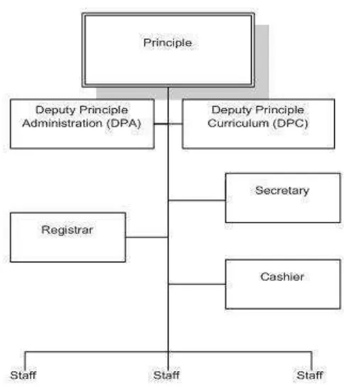
their studies to college or university. It is a boarding school whereby students choose to register/enroll whether as a boarding or a day student at the beginning of the academic year. There are four schooling terms annually with holiday at the end of each term. From 2008 statistics: total number of staffs=35, total number of students=660. The school is administered by the Principle with his/her two Deputies: Deputy Principle Administration (DPA) and Deputy Principle Curriculum (DPC).
Since the establishment of Fr. Peter Secondary School until now, the school’s system is mainly managed manually. That includes enrollment process, registration, school fee payment, creation of class schedules, and others. Consequently, a lot of problems do occur at the beginning of every new academic year like: late commencement of classes; number of new intakes normally exceed the maximum number of students required so this results in over-populated in the classrooms as well as dormitories; clashes in class schedules as well as no proper screening of teachers in order to allocate the right subjects according to their qualifications; and so many other problems.
system, Fr. Peter Secondary School is in great need to improvise its management system in order to adapt to this information or digital age. To produce bright students and achieve its long term goals, the system of the school needs to be changed from manual-based to an automated-based system. Automation is the utilization of technology to replace human with a machine (especially computer) that can perform more quickly and more continuously That is, the automated-based school management system consists of tasks such as registration and enrollment processes, staff profiling and creating class schedules, manage financial recordings, producing student transcripts, and so on. This would greatly have impact on the school’s progress and academic performance. As a result, Fr. Peter Secondary School can be able to produce bright students and could be ranked among the top secondary schools in Papua New Guinea.
3.1.2. Organizational Structure of Fr. Peter Secondary School
Figure 3.1 Organizational Structure of Fr. Peter Secondary School
3.2. Research Methods
3.2.1. Research Design
According to Green and Tull, “It is the specification of techniques and
processes for obtaining the information required. It is the over-all operational pattern or framework of the project which states what data is to be gathered from which source by what process”
The research design is defined as the plan for collecting and utilizing data so that desired information can be obtained. It is a thorough outline of how a study is going to take place. That is, how data can be collected, what tools will be used, how the tools will be used and the intended means for analyzing collected data.
3.2.2. Types and Data Collection Methods
The type and data collection methods are as follows:
3.2.2.1. Collecting Primary Data
Primary data are data that were previously unknown and which have been obtained directly by the researcher for a particular research project. In this research, these two methods of collecting primary data were taken into consideration:
1. The Observational Method
2. The Interview Method
This technique of data collection is simply a face-to-face conversation with the involvement of questioners. According to Arnold (et al 1991), “The interview is, in effect, often used as a „talking questionnaire’”. So the researcher through direct phone call conversation with the respective representatives (staffs) at Fr. Peter Secondary made it possible to get the vital data or information needed.
3.2.2.2. Collecting Secondary Data
Secondary data is collected from data sources that are already existed. In this research, the researcher collected data from previous research, web information, and historical data and information about Fr. Peter Secondary School.
3.2.3. Method and System Development Approach
In this section, it explains about the systems approach, the development of systems, methods of analysis and design analysis tools. Following is the description of the approach and system development.
3.2.3.1. Systems Approach Method
Class Diagrams, Collaboration Diagrams, Component Diagrams, and Deployment Diagrams.
According to Jian Wang (Information System Analysis Section G01-Fall 2001), “The object-oriented approach combines data and processes (called methods) into single entities called objects. Objects usually correspond to the real things an information system deals with, such as customers, suppliers, contracts, and rental agreements. Object-oriented model is able to thoroughly represent complex relationships and to represent data and data processing with a consistent notation, which allows an easier blending of analysis and design in an evolutionary process.” And according to Hoffer (et al. 2002), “The goal of object-oriented approach is to make system elements more reusable, thus improving system quality and the productivity of systems analysis and design”.
3.2.3.2. Systems Development Method
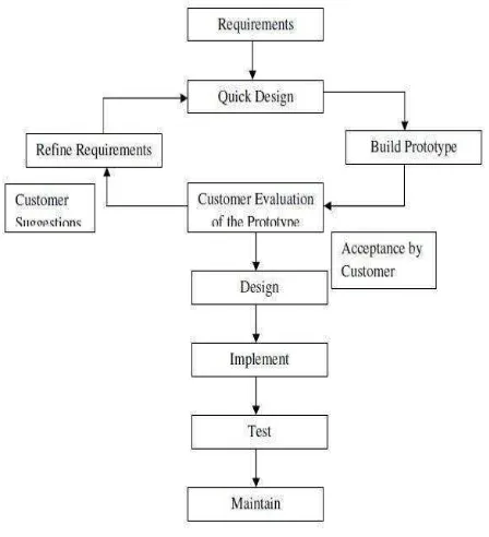
According to Sona Malhotra (International Journal of Advance in Information Technology), ” Instead of freezing the requirements before a design or coding can proceed, a throwaway prototype is built to understand the requirements. This prototype is developed based on the currently known requirements. Prototyping is an attractive idea for complicated and large systems for which there is no manual process or existing system to help determining the requirements. A prototype is a toy implementation of a system; usually exhibiting limited functional capabilities, low reliability, and inefficient performance.”
Figure 3.2 Prototype Model ( Source:Seema, Sona Malhotra- ”International
Following is the stepwise approach taken to design Fr. Peter Secondary School Management System’s software prototype:
1. Basic Requirement Identification : This step involves understanding the very basics system requirements of Fr. Peter Secondary School system especially in terms of user interface. The more intericate details of the internal design and external aspects like performance and security were ignored at this stage.
2. Developing the initial Prototype: The initial Prototype of Fr. Peter Secondary School Management System was developed in this stage, where the very basic requirements were showcased and user interface were provided. These features may not exactly work in the same manner internally in the actual software developed and the workarounds were used to give the same look and feel to the customer in the prototype developed.
3. Review of the Prototype: The prototype of the school system developed was then presented to the customer and the other important stakeholders in the research. The feedback were collected in an organized manner and used for further enchancements in the system development.
3.2.3.3. Analysis and Design Tools
With a systems approach that is object-oriented, the researcher used a modeling language called the Unified Modeling Language (UML). According to IBM (ibm.com website), UML is a visual language for specifying, constructing, and documenting the artifacts of systems. Therefore, the developing system is visualized by the following UML diagrams:
1. Class Diagram
Class diagrams are the most common diagrams used in UML. Class diagram consists of classes, interfaces, associations and collaboration. Class diagrams basically represent the object oriented view of a system which is static in nature. Active class is used in a class diagram to represent the concurrency of the system. Class diagram represents the object orientation of a system. So it is generally used for development purpose. This is the most widely used diagram at the time of system construction.
2. Deployment Diagram
3. Use case Diagram
Use case diagrams are a set of use cases, actors and their relationships. They represent the use case view of a system. A use case represents a particular functionality of a system. So use case diagram is used to describe the relationships among the functionalities and their internal/external controllers. These controllers are known as actors.
4. Activity Diagram
Activity diagram describes the flow of control in a system. So it consists of activities and links. The flow can be sequential, concurrent or branched. Activities are nothing but the functions of a system. Numbers of activity diagrams are prepared to capture the entire flow in a system. Activity diagrams are used to visualize the flow of controls in a system. This is prepared to have an idea of how the system will work when executed.
3.2.4. Testing Software
For example, in a black box test on a software design the tester only knows the inputs and what the expected outcomes should be and not how the program arrives at those outputs. The tester does not ever examine the programming codeand does not need any further knowledge of the program other than its specifications.”
Black Box Testing - Steps
Here are the generic steps followed to carry out any type of Black Box Testing.
1. Initially requirements and specifications of the system are examined.
2. Tester chooses valid inputs (positive test scenario) to check whether SUT processes them correctly . Also some invalid inputs (negative test scenario) are chosen to verify that the SUT is able to detect them.
3. Tester determines expected outputs for all those inputs. 4. Software tester constructs test cases with the selected inputs. 5. The test cases are executed.
6. Software tester compares the actual outputs with the expected outputs. 7. Defects if any are fixed and re-tested.
3.2.5. Analysis of Current System
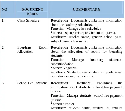
3.2.5.1. Analysis of Document
Analysis of the document is to analyze the activities of all documents that are used on the basis of an information system that is running. As for the types of documents used in Fr. Peter Secondary School system is: Class Schedule, Room Allocation (Boarding), School Fee Payment, Enrollment, Student Academic Performance, and Registration. Here are the details of each of these documents:
Table 3.1 Document Analysis Table
NO DOCUMENT NAME
COMMENTARY
1 Class Schedule Description: Documents containing information about the teaching schedules.
Function: Manage class schedules
Source: Deputy Principle Cirriculum (DPC). Attribute: Teacher name, gender, school year, subject name, class name.
2 Boarding Room
Allocation
Description: Documents containing information about the allocation of rooms for boarding students.
Function: Manage boarding students’ accommodation.
Source: Registrar
Attribute: Student name, student id, grade level, dormitory name, room number.
3 School Fee Payment Description: Documents containing the information about students’ school fee payment process.
Function: Manage students’ school fee payment process.
Source: Cashier
paid, balance, amount yet to pay, year, grade level.
4 Enrollment Description: Documents containing information about the students’ enrollment process.
Function: Manage the students’ enrollment
process.
Source: Enrollment Encoder (staff)
Attribute: Student name, student id, school year, gender, grade level, class name.
5 Student Academic
Performance
Description: Documents containing information about students’ academic performance or grades.
Function: Produce students’ academic transcripts
Source: Teacher
Attribute: Student name, student id, grade level, class name, subject grade, gender, class patron name, subject,
6 Registration Description: Documents containing information about the students’ registration process.
Function: Manage the students’ registration
process.
Source: Registrar
Attribute: Student name, student id, place of birth, date of birth, citizen, fathers name, mothers name, address, school year, gender, grade level, class name, etc.
3.3. Analysis of Current Procedures
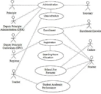
3.3.1. Use Case Diagram of School System The Ongoing
Figure 3.3 Use Case Diagram of School System the Ongoing
3.3.1.1. Scenario Use Case Diagram of School System The Ongoing
The Scenario Use Case Diagram that is running is as follows:
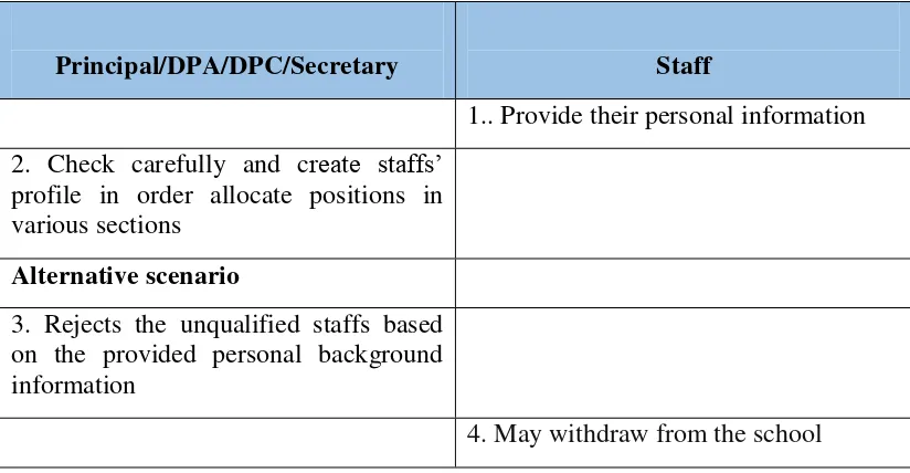
1. Scenario Use Case Diagram Administration
1 Use Case Name: Administration.
2 Main Actor: Principal, DPA/DPC, Secretary
3 Purpose: Manage staffs (that includes teachers, registrar, cashier, auxiliary, etc), create class schedules, and manage other sections.
Table 3.2 Scenario Use Case Diagram Administration The Ongoing
Principal/DPA/DPC/Secretary Staff
1.. Provide their personal information 2. Check carefully and create staffs’
profile in order allocate positions in various sections
Alternative scenario
3. Rejects the unqualified staffs based on the provided personal background information
4. May withdraw from the school
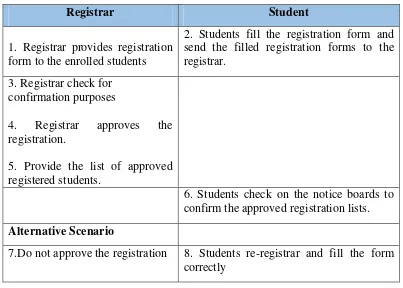
2. Scenario Use Case Diagram Registration
The scenario of the use case diagram registration in the current system is as follows: 1 Use Case Name: Registration
2 Main Actor: Registrar, Student
Table 3.3 Scenario Use Case Registration the Ongoing
Registrar Student
1. Registrar provides registration form to the enrolled students
2. Students fill the registration form and send the filled registration forms to the registrar.
3. Registrar check for confirmation purposes
4. Registrar approves the registration.
5. Provide the list of approved registered students.
6. Students check on the notice boards to confirm the approved registration lists.
Alternative Scenario
7.Do not approve the registration 8. Students re-registrar and fill the form correctly
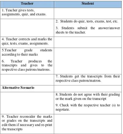
3. Scenario Use Case Diagram Student Academic Performance
The scenario of the use case diagram student academic performance in the current system is as follows:
1 Use Case Name: Student Academic Performance
2 Main Actor: Teacher, Student
Table 3.4 Scenario Use Case Student Academic Performance the Ongoing
Teacher Student
1. Teacher gives tests,
assignments, quiz, and exams.
2. Students do quiz, tests, exams, test, etc. 3. Students submit the answer/answer sheets to the teacher.
4. Teacher corrects and marks the quiz, tests, exams, assignments. 5.Teacher grade students according to their marks
6. Teacher produces the
or the mark given on the transcript
9. Check with the respective teacher (s) to negotiate.
9. Teacher reconsider the marks or grades on the transcripts and edit them if necessary and re-print the transcripts
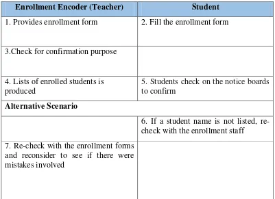
4. Scenario Use Case Diagram Enrollment
2 Main Actor: Enrollment Encoder (teacher/staff), Student 3 Purpose: Manage the enrollment process.
Table 3.5 Scenario Use Case Diagram Enrollment the ongoing Enrollment Encoder (Teacher) Student
1. Provides enrollment form 2. Fill the enrollment form
3.Check for confirmation purpose
4. Lists of enrolled students is produced
5. Students check on the notice boards to confirm
Alternative Scenario
6. If a student name is not listed, re-check with the enrollment staff
7. Re-check with the enrollment forms and reconsider to see if there were mistakes involved
5. Scenario Use Case Diagram School Fee Payment
The scenario of the use case diagram school fee payment in the current system is as follows:
2 Main Actor: Cashier, Student
3 Purpose: Manage accounting work and financial records
Table 3.6 Scenario Use Case School Fee Payment the Ongoing
Cashier Student
1, Pay the school fee upfront at school (cashier’s office) or pay at the bank to the school’s account and get the receipt
2.Give the paid school fee receipt to the Cashier (if paid at the bank)
3.Check to confirm and do the financial records
Alternative Scenario
5. If check and realized that the amount paid is less than the required amount, a list of notice is produced to the respective students
.
6.Top up again on the amount already paid to meet the required amount of school fee payment
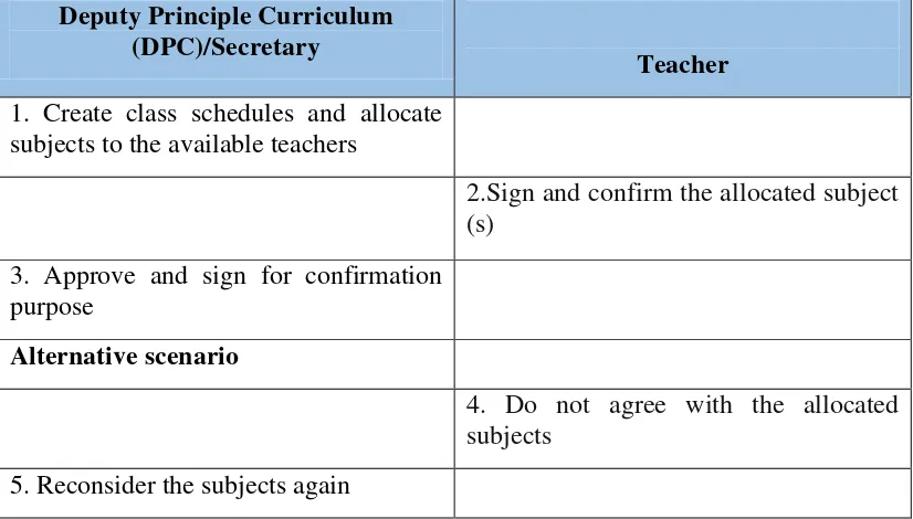
6. Scenario Use Case Diagram Class Schedule
The scenario of the use case diagram class schedule in the current system is as follows:
1 Use Case Name: Class Schedule
3 Purpose: Make class schedules for the teachers
Table 3.7 Scenario Use Case Diagram Class Schedule The Ongoing Deputy Principle Curriculum
(DPC)/Secretary
Teacher
1. Create class schedules and allocate subjects to the available teachers
2.Sign and confirm the allocated subject (s)
3. Approve and sign for confirmation purpose
Alternative scenario
4. Do not agree with the allocated subjects
5. Reconsider the subjects again
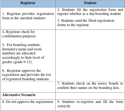
7. Scenario Use Case Diagram Boarding Room Allocation
The scenario of the use case diagram boarding room allocation in the current system is as follows:
1 Use Case Name: Boarding Room Allocation 2 Main Actor: Registrar
Table 3.8 Scenario Use Case Diagram Boarding Room Allocation The Ongoing
Registrar Student
1. Registrar provides registration form to the enrolled students
2. Students fill the registration form and register whether as a day/boarding student 3. Students send the filled registration forms to the registrar.
4. Registrar check for confirmation purposes 5. For boarding students, dormitory name and room numbers are allocated accordingly to their level of grades (grade 9-12).
6. Registrar approves the registration and provides the list of registered boarding students.
7. Students check on the notice boards to confirm their names on the boarding lists.
Alternative Scenario
8. Do not approve the registration 9. Students re-registrar and fill the form correctly
3.3.2. Activity Diagram System The Ongoing
The activity of school system that is running at the moment is as follows:
1. Activity Diagram Administration The Ongoing
Figure 3.4 Activity Diagram Administration The ongoing
2. Activity Diagram Registration The Ongoing
Figure 3.5 Activity Diagram Registration The Ongoing
3. Activity Diagram Student Academic Performance The Ongoing
Figure 3.6 Activity Diagram Student Academic Performance The Ongoing
produces transcripts and gives to the respective class patrons/matrons so students get their transcripts from them.
4. Activity Diagram Enrollment The Ongoing
Figure 3.7 Activity Diagram Enrollment The Ongoing
fill the enrollment forms and send them back. The staff checks the filled forms thoroughly and enrolls the students. However, those that are unaccepted have to re-enroll again by filling the forms again.
5. Activity Diagram School Fee Payment The Ongoing
The figure above describes the flow of school fee payment at Fr. Peter Secondary School. The students pay upfront at the Cashier’s office or provide the school fee payment receipt (if they paid at the bank) to the cashier. The cashier checks and does the financial recordings. However, those students that did not meet the required amount of school fee payment have to re-pay again.
6. Activity Diagram Class Schedule The Ongoing
The figure above describes the flow of the class schedule at Fr. Peter Secondary School. The school’s Administration especially the Deputy Principle Curriculum/Secretary makes the profile of every staffs/teachers and according to their personal information and educational background; class schedule is created. The schedule is given to the teachers so they can sign and confirm it. If a teacher is disagreeing with the given class schedule, a review is made by the Administration to re-schedule.
7. Activity Diagram Boarding Room Allocation The Ongoing
The figure above describes the flow of boarding room allocation at Fr. Peter Secondary School. The registrar provides the registration form to the students. The students fill up the form and choose whether to be a boarding or a day student and send back the forms to the registrar. The completed filled forms are checked by the registrar and for the boarding students; rooms are only allocated to those that have met the requirement. However, for those students that have not met the requirement to be a boarding student, they re-register accordingly again.
3.3.3. Ongoing Evaluation System
After passing through several stages of analysis of School System that is running in Fr. Peter Secondary School, it can be seen that there are deficiencies in the system; these shortcomings are described in the following table:
Tabel 3.9 Evaluation System the Ongoing
No Problem Part Settlement plan
1 Making class schedules manually normally results in timetable collisions or clashes
2 Over-crowded in the
65
4.1. System Design
System design is the process of defining the components, modules, interfaces, and data for a system to satisfy specified requirements. Systems design could be seen as the application of systems theoryto product development.
4.1.1. System Design Objective
1. The application of the web-based Fr. Peter Secondary School Management System can manage staffs and students personal information (profiling), subjects and teachers, boarding student accommodation, class advisory, creating class schedules or timetables, and manage other sections.
2. The web-based system can perform accounting and financial records processes more effectively especially the payment of student’s school fee. 3. The new system could manage student enrollment and registration processes
in a well-organized manner and more effectively.
4.1.2. Proposed System Overview
The proposed system for Fr. Peter Secondary School Management System is particulary a web-based systemthat usesthe concept of client-server, in whichthe client uses a browser while PHP and MySql are used as the server. This is done online so other users or clients can access these applications through using the internet.
Figure 4.1Client – Server Scheme
4.1.3. Proposed Design Procedure
4.1.3.1. Use Case Diagram
Use case describes an interaction between one or more actors with information systems that will be made. The use case is used to determine what function is in an information system and who is entitled to use those functions. The following is the use case diagram of the proposed web-based school management system at Fr. Peter Secondary School.
4.1.3.2. Scenario Use Case
Use case scenarios are used to make it easier to analyze scenarios that will be used in subsequent phases by assessing these scenarios, the following use case scenarios proposed.
1. Scenario Use Case Administration.
The use case scenario Administration in the proposed Fr. Peter Secondary School system is as follows:
1. Name of the use case : Administration 2. The main actors : Admin/ Secretary
3. Purpose : To manage administration activities like managing staffs’ profiles, subjects and subject allocations, create class schedules, boarding students accommodations, create class advisory, and manage other sections such as registration, enrollment, finance, and the whole system.
Table 4.1 Scenario Administration Use Case
Admin/Secretary System
1. Displays the Login page
2. Fill in the User Name and Password and click Login
3. Displays the Menu page
4. Select
“Administrative”
-Menus” information and click “Save”
12. Displays the word “Successful” with Green color background
AlternativeScenario
13. If one of the field is empty, the system only highlights those empty fields with a Red background color
9. Re-fill all the fields as required
1. Scenario Use Case Registration
The use case scenario Registration in the proposed Fr. Peter Secondary School Management System is as follows:
1. Name of the use case : Registration
2. Main actor : Registrar/Admin
Tabel 4.2 Scenario Registration Use Case
Registrar/Admin System
1. Display the Login page 2. Fill in the User Name and
Password and click Login
3. Display menu page 4. Choose “Registration”
5. Shows sub-menus 6. Select “Students”
7. Displays the empty form with options “Add” and Delete”
8. Click “Add” to register a new student
9. Display the
registration form 10. Fill the registration
and click “Save”
11. Displays the word “Successful” with Green color background
AlternativeScenario
12. If one of the field is empty, the system only highlights those empty fields with a Red background color 10. Re-fill the form
completely
2. Scenario Use Case Enrollment
The use case scenario Enrollment in the proposed Fr. Peter Secondary Management System is as follows:
1. Name of the use case : Enrollment
3. Purpose : Perform enrollment process of the school
Tabel 4.3 Scenario Enrollment Use Case Registrar/Admin System
1. Display Login page 2. Fill in the User Name
and Password and click Login
3. Display menu page 4. Select “Enrollment”
and click it
5. Displays the empty form with options “Add” and Delete” 6. Choose “Add” to
enroll a new student
7. Display form empty, the system only highlights those empty fields with a Red background color 11. Re-fill all the fields
3. Scenario Use Case Accounting &Financial Records
1. Name of the use case : Accounting &Financial Records
2. Main actor : Cashier/Admin
3. Purpose : Perform all accounting and financial tasks and produce student school fee ledger.
Tabel 4.4 Scenario Accounts &Financial Records Use Case
Cashier/Admin System
1. Shows the Login page 2. Fill the User Name and
Password and click Login
3. Display the Menu Page 4. Select Cashier
5. Displays Sub-menu lists 6. Choose “Payment”
7. Shows the payment form 8. Fill in the form and
click “Save”
9. Displays the word “Successful” with Green color background
4. Scenario Use Case Student Information
The use case scenario Students Informationin the proposed Fr. Peter Secondary School System is as follows:
2. Main actor : Student
3. Purpose : For student to see and print his/her transcript, class timetable, and school fee ledger
Tabel 4.5 Scenario Student Information Use Case
Student System
1. Displaythe Login page
7. Displays the transcript 8. Click “Print” to message “Wrong User Name or Password” will be displayed when trying to Login
Activity Diagram of the Proposed New System
Activity diagram below shows in detail the logical data flow without considering the physical environment in which the data flows. Here is the proposed activity on the application of Fr. Peter Secondary School Management System.
1. Activity Diagram Administration
This section describes the workflow of the proposed Administration system in the proposed new system of Fr. Peter Secondary School.
The Activity diagram is as follows:
2. Activity Diagram Registration
This section describes the workflow of the proposed Registration system in the proposed new system.
The Activity diagram is as follows:
Figure 4.4 Activity Diagram Registration Proposed
3. Activity Diagram Enrollment
The Activity diagram is as follows:
Figure 4.5 Activity Diagram Enrollment Proposed
4. Activity Diagram Accounting &Financial Records
This section describes the workflow of the proposed Financial Records system in the proposed new system of Fr. Peter Secondary School.
Figure 4.6 Activity Diagram Accounting &Financial Records Proposed
5. Activity Diagram Student Information
This section describes the workflow of the proposed Student Information in the proposed new system.
Figure 4.7 Activity Diagram of the proposed Student Information
4.1.3.3. Sequence Diagram
A sequence diagram is an interaction diagram. It deals with some sequences, which are the sequence of messages flowing from one object to another. To see the interaction between objects, the following describe the sequence diagram of each identified use cases.
1. Sequence Diagram Administration (Create Class Timetable)
2. Sequence Diagram Registration
3. Sequence Diagram Enrollment
4. Sequence Diagram Accounting & Financial Records
5. Sequence Diagram Student Information (View Student Grades)
Figure 4.12 Sequence Diagram Student Information (View Student Grades)
4.1.3.4. Class Diagram
Class diagrams are the most common diagrams used in UML. Class diagram consists of classes, interfaces, associations and collaboration. Class diagrams basically represent the object oriented view of a system which is static in nature.
4.1.3.5. Deployment Diagram
Deployment diagrams are a set of nodes and their relationships. These nodes are physical entities where the components are deployed.
Figure 4.14 Deployment Diagram
4.1.3.6. Network Architecture of the Proposed System
The proposed system is expected to replace the existing manual system by an automated system in all facets. It is mainly based on the system Analysis document (chapter 3).
system within the local area network of the school or any where using the Internet. Figure 4.14 below shows the network architecture of the proposed system.
The data tier maintains the applications data such as student data, teacher data, timetable data, etc. It stores these data in a relational database management system (RDBMS).
The middle tier (web/application server) implements the business logic, controller logic and presentation logic to control the interaction between the application’s clients and data. The controller logic processes client requests such as requests to view student’s grades, to register/ enroll students or to retrieve data from
the database. Business rules enforced by the business logic dictate how clients can and cannot access application data and how applications process data.
A web server is a program that runs on a network server (computer) to respond to HTTP requests. The most commonly used web servers are Internet Information Server (IIS) and Apache. The web server used in this system is Apache. HTTP is used to transfer data across an Intranet or the Internet. It is the standard protocol for moving data across the internet.
The Network Architecture of the Proposed System is shown below:
Figure 4.15 Network Architecture
4.2. Implementation
The implementation of this prototype application of Fr. Peter Secondary School Management System is done using PHP and Smarty, MySQL as the database and through using Apache HTTP Server (XAMPP) as the web server. This application is implemented on Windows 7 Operating System.
feedbacks, this system could be (or not) further re-build in order to satisfy the users’ needs. .
4.2.1. Implementation Limits
The limit on the implementation of Fr. Peter Secondary School Management System includes:
1. Implementation of this application is only accessible by four users: admin/secretary, registrar, cashier and student.
2. Implementation of the application is only built for Fr. Peter Secondary School.
4.2.2. Software Implementation
The application can be installed on a PC or laptop with Windows 7 operating system. The required softwares to be used in the PC/laptop for the implementation of this system is as follows:
1. Operating System -Windows 7
2. XAMPP-2.5 for Internet and creating local database and data storage. 3. Smarty
4. PHP Storm, Notepad ++, Macromedia Dreamweaver 8, to write coding. 5. Mozilla Firefox as a browser.
4.2.3. Hardware Implentation
In order to to run the designed application,it needs hardware to rely on. The hardware requirements are as follows:
2. Memory: 2GB RAM 3. Hard drive: 500GB
4.2.4. Database Implementation (SQL syntax)
Database Implementation taken is based on the design of the database that was created for this system. The following table structure was implemented in the database with their respective indexes:
1. “tbl_class_advisory”
CREATE TABLE IF NOT EXISTS `tbl_class_advisory` ( `Id` int(11) NOT NULL,
`SchoolYear` int(11) DEFAULT NULL,
`SchoolYearName` varchar(50) COLLATE latin1_general_ci DEFAULT NULL,
`Teacher` int(11) DEFAULT NULL,
`TeacherName` varchar(50) COLLATE latin1_general_ci DEFAULT NULL,
`YearLevel` int(11) DEFAULT NULL,
`YearLevelName` varchar(50) COLLATE latin1_general_ci DEFAULT NULL,
`ClassName` int(11) DEFAULT NULL,
`ClassNameText` varchar(50) COLLATE latin1_general_ci DEFAULT NULL,
`Created` datetime DEFAULT NULL,
`Creator` varchar(50) COLLATE latin1_general_ci DEFAULT NULL, `Updated` datetime DEFAULT NULL,
`Updater` varchar(50) COLLATE latin1_general_ci DEFAULT NULL )
Indexes for table `tbl_class_advisory` ALTER TABLE `tbl_class_advisory` ADD PRIMARY KEY (`Id`),
ADD KEY `FK1` (`SchoolYear`,`SchoolYearName`), ADD KEY `FK2` (`Teacher`,`TeacherName`),
2. “tbl_enrollment”
CREATE TABLE IF NOT EXISTS `tbl_enrollment` ( `Id` int(11) NOT NULL,
`SchoolYear` int(11) DEFAULT NULL,
`SchoolYearName` varchar(50) COLLATE latin1_general_ci DEFAULT NULL,
`YearLevel` int(11) DEFAULT NULL,
`YearLevelName` varchar(50) COLLATE latin1_general_ci DEFAULT NULL,
`ClassName` int(11) DEFAULT NULL,
`ClassNameText` varchar(50) COLLATE latin1_general_ci DEFAULT NULL,
`Student` int(11) DEFAULT NULL,
`StudentId` varchar(30) COLLATE latin1_general_ci DEFAULT NULL, `StudentName` varchar(50) COLLATE latin1_general_ci DEFAULT NULL,
`Balance` double DEFAULT NULL, `Created` datetime DEFAULT NULL,
`Creator` varchar(50) COLLATE latin1_general_ci DEFAULT NULL, `Updated` datetime DEFAULT NULL,
`Updater` varchar(50) COLLATE latin1_general_ci DEFAULT NULL )
Indexes for table `tbl_enrollment` ALTER TABLE `tbl_enrollment` ADD PRIMARY KEY (`Id`),
3. “tbl_fee_paid”
CREATE TABLE IF NOT EXISTS `tbl_fee_paid` ( `Id` int(11) unsigned NOT NULL,
`AmountReceived` double DEFAULT '0', `Balance` double DEFAULT '0',
`SchoolYear` int(11) DEFAULT NULL,
`SchoolYearName` varchar(50) COLLATE latin1_general_ci DEFAULT NULL,
`YearLevel` int(11) DEFAULT NULL,
`YearLevelName` varchar(50) COLLATE latin1_general_ci DEFAULT NULL,
`Student` int(11) DEFAULT NULL,
`StudentId` varchar(50) COLLATE latin1_general_ci DEFAULT NULL, `StudentName` varchar(50) COLLATE latin1_general_ci DEFAULT NULL,
`TimePaid` datetime DEFAULT NULL, `Cashier` int(11) DEFAULT NULL,
`CashierName` varchar(50) COLLATE latin1_general_ci DEFAULT NULL
)
Indexes for table `tbl_fee_paid` ALTER TABLE `tbl_fee_paid` ADD PRIMARY KEY (`Id`);
4. “tbl_log_user”
CREATE TABLE IF NOT EXISTS `tbl_log_user` ( `id_log` int(10) unsigned NOT NULL,
`user_id` int(10) unsigned DEFAULT NULL, `time_login` datetime DEFAULT NULL, `time_logout` datetime DEFAULT NULL,
`user_ip` varchar(100) COLLATE latin1_general_ci DEFAULT NULL )
5. “tbl_md_boarding”
CREATE TABLE IF NOT EXISTS `tbl_md_boarding` ( `Id` int(11) NOT NULL,
`BoardingName` varchar(50) COLLATE latin1_general_ci DEFAULT NULL,
`Gender` char(1) COLLATE latin1_general_ci DEFAULT NULL, `MaxStudentsAllowed` int(3) DEFAULT NULL,
`Created` datetime DEFAULT NULL,
`Creator` varchar(100) COLLATE latin1_general_ci DEFAULT NULL,
`Updated` datetime DEFAULT NULL,
`Updater` varchar(100) COLLATE latin1_general_ci DEFAULT NULL
)
Indexes for table `tbl_md_boarding` ALTER TABLE `tbl_md_boarding` ADD PRIMARY KEY (`Id`), ADD KEY `Id` (`Id`);
6. “tbl_md_fee”
CREATE TABLE IF NOT EXISTS `tbl_md_fee` ( `Id` int(11) unsigned NOT NULL,
`FeeName` varchar(50) COLLATE latin1_general_ci DEFAULT '', `Description` varchar(255) COLLATE latin1_general_ci DEFAULT '',
`Amount` double DEFAULT NULL, `YearLevel` int(11) DEFAULT NULL,
`YearLevelName` varchar(3) COLLATE latin1_general_ci DEFAULT NULL,
`IsBoarding` int(1) DEFAULT '0', `Created` datetime DEFAULT NULL,
`Creator` varchar(50) COLLATE latin1_general_ci DEFAULT NULL,
`Updated` datetime DEFAULT NULL,
`Updater` varchar(50) COLLATE latin1_general_ci DEFAULT NULL
Indexes for table `tbl_md_fee` ALTER TABLE `tbl_md_fee` ADD PRIMARY KEY (`Id`);
7. “tbl_md_school_year”
CREATE TABLE IF NOT EXISTS `tbl_md_school_year` ( `Id` int(11) NOT NULL,
`SchoolYear` varchar(15) COLLATE latin1_general_ci DEFAULT NULL,
`IsActive` int(1) DEFAULT '0', `Created` datetime DEFAULT NULL,
`Creator` varchar(50) COLLATE latin1_general_ci DEFAULT NULL,
`Updated` datetime DEFAULT NULL,
`Updater` varchar(50) COLLATE latin1_general_ci DEFAULT NULL
)
Indexes for table `tbl_md_school_year` ALTER TABLE `tbl_md_school_year` ADD PRIMARY KEY (`Id`),
ADD KEY `Id` (`Id`,`SchoolYear`);
8. “tbl_md_sections”
CREATE TABLE IF NOT EXISTS `tbl_md_sections` ( `Id` int(11) NOT NULL,
`SectionName` varchar(100) COLLATE latin1_general_ci DEFAULT NULL,
`YearLevel` int(11) DEFAULT NULL,
`ClassName` varchar(100) COLLATE latin1_general_ci DEFAULT NULL,
`MaxStudentsAllowed` int(3) DEFAULT NULL, `Created` datetime DEFAULT NULL,
`Updated` datetime DEFAULT NULL,
`Updater` varchar(100) COLLATE latin1_general_ci DEFAULT NULL
)
Indexes for table `tbl_md_sections` ALTER TABLE `tbl_md_sections` ADD PRIMARY KEY (`Id`), ADD KEY `FK_01` (`YearLevel`), ADD KEY `Id` (`Id`,`ClassName`);
9. “tble_md_students”
CREATE TABLE IF NOT EXISTS `tbl_md_students` ( `Id` int(11) unsigned NOT NULL,
`StudentId` varchar(30) COLLATE latin1_general_ci DEFAULT NULL,
`StudentName` varchar(50) COLLATE latin1_general_ci DEFAULT NULL,
`Gender` char(1) COLLATE latin1_general_ci DEFAULT NULL,
`BirthDate` date DEFAULT NULL,
`BirthPlace` varchar(50) COLLATE latin1_general_ci DEFAULT NULL,
`Citizen` varchar(50) COLLATE latin1_general_ci DEFAULT NULL,
`Religion` varchar(50) COLLATE latin1_general_ci DEFAULT NULL,
`BloodType` char(2) COLLATE latin1_general_ci DEFAULT NULL,
`StudentContact` varchar(30) COLLATE latin1_general_ci DEFAULT NULL,
`Boarding` int(11) DEFAULT NULL,
`BoardingName` varchar(50) COLLATE latin1_general_ci DEFAULT NULL,
10. “tbl_md_subjects”
CREATE TABLE IF NOT EXISTS `tbl_md_subjects` ( `Id` int(11) NOT NULL,
`Subject` varchar(50) COLLATE latin1_general_ci DEFAULT NULL,
`Description` varchar(255) COLLATE latin1_general_ci DEFAULT NULL,
`YearLevel` int(11) DEFAULT NULL, `Created` datetime DEFAULT NULL,
`BedNumber` varchar(10) COLLATE latin1_general_ci DEFAULT NULL,
`MotherName` varchar(30) COLLATE latin1_general_ci DEFAULT NULL,
`MotherOccupation` varchar(50) COLLATE latin1_general_ci DEFAULT NULL,
`FatherName` varchar(30) COLLATE latin1_general_ci DEFAULT NULL,
`FatherOccupation` varchar(50) COLLATE latin1_general_ci DEFAULT NULL,
`ParentContact` varchar(30) COLLATE latin1_general_ci DEFAULT NULL,
`Address` text COLLATE latin1_general_ci,
`LastSchoolAttend` varchar(50) COLLATE latin1_general_ci DEFAULT NULL,
`LastSchoolContact` varchar(30) COLLATE latin1_general_ci DEFAULT NULL,
`LastSchoolAddress` text COLLATE latin1_general_ci, `StudentPassword` text COLLATE latin1_general_ci, `Created` datetime DEFAULT NULL,
`Creator` varchar(50) COLLATE latin1_general_ci DEFAULT NULL,
`Updated` datetime DEFAULT NULL,
`Updater` varchar(50) COLLATE latin1_general_ci DEFAULT NULL
)
`Creator` varchar(50) COLLATE latin1_general_ci DEFAULT NULL,
`Updated` datetime DEFAULT NULL,
`Updater` varchar(50) COLLATE latin1_general_ci DEFAULT NULL
)
Indexes for table `tbl_md_subjects` ALTER TABLE `tbl_md_subjects` ADD PRIMARY KEY (`Id`);
11.“tbl_md_year_level”
CREATE TABLE IF NOT EXISTS `tbl_md_year_level` ( `Id` int(11) NOT NULL,
`YearLevel` varchar(3) COLLATE latin1_general_ci DEFAULT NULL,
`Description` text COLLATE latin1_general_ci, `Created` datetime DEFAULT NULL,
`Creator` varchar(100) COLLATE latin1_general_ci DEFAULT NULL,
`Updated` datetime DEFAULT NULL,
`Updater` varchar(100) COLLATE latin1_general_ci DEFAULT NULL
)