DESIGN OF WATER LEVEL CONTROL TRAINING KIT
ZULHALMI BIN DARWIS
B050810316
UNIVERSITI TEKNIKAL MALAYSIA MELAKA
UNIVERSITI TEKNIKAL MALAYSIA MELAKA
DESIGN OF WATER LEVEL CONTROL TRAINING KIT
This report submitted in accordance with requirement of the Universiti Teknikal Malaysia Melaka (UTeM) for the Bachelor Degree of Manufacturing Engineering
(Robotic and automation)
by
ZULHALMI BIN DARWIS
B050810316
UNIVERSITI TEKNIKAL MALAYSIA MELAKA
BORANG PENGESAHAN STATUS LAPORAN PSM
JUDUL: “DESIGN OF WATER LEVEL CONTROL TRAINING KIT”
SESI PENGAJIAN: 2/2008-2009
Saya ZULHALMI BIN DARWIS
mengaku membenarkan tesis (PSM/Sarjana/Doktor Falsafah) ini disimpan di Perpustakaan Universiti Teknikal Malaysia Melaka (UTeM) dengan syarat-syarat kegunaan seperti berikut:
1. Tesis adalah hak milik Universiti Teknikal Malaysia Melaka dan penulis.
2. Perpustakaan Universiti Teknikal Malaysia Melaka dibenarkan membuat salinan untuk tujuan pengajian sahaja dengan izin penulis.
3. Perpustakaan dibenarkan membuat salinan tesis ini sebagai bahan pertukaran antara institusi pengajian tinggi.
4. *Sila tandakan (√)
SULIT
TERHAD
TIDAK TERHAD
(Mengandungi maklumat yang berdarjah keselamatan atau kepentingan Malaysia yang termaktub di dalam AKTA RAHSIA RASMI 1972)
(Mengandungi maklumat TERHAD yang telah ditentukan oleh organisasi/badan di mana penyelidikan dijalankan)
DECLARATION
I hereby declare that this report entitled “Design of Water Level Control Training Kit” is the result of my own research except as cited in the references.
Signature :
Author’s Name : Zulhalmi Bin Darwis
APPROVAL
This report is submitted to the Faculty of Manufacturing Engineering of UTeM as a partial fulfillment of the requirements for the degree of Bachelor of Manufacturing Engineering (Robotic and Automation). The members of the supervisory committee are
as follow:
……… (Madam Nur Aidawaty Binti Rafan)
Main Supervisor
ABSTRAK
ABSTRACT
This project describes the development of water level control training kit using a programming. It provides a stimulation to get water level data. This project is suitable
for the student’s usage to make easier when doing the experiment that related water
DEDICATION
I dedicate this PSM thesis to my beloved parents, my lovely brothers, friends and
ACKNOWLEDGEMENT
Alhamdullilah, with the Bless from Allah the All Mighty, finally I have completed the final year project and thesis writing on time. Firstly I would like to express my appreciation to my supervisor Puan Nur Aidawaty Rafan for her guidance, advice and continuous encouragement in process of completing my project successfully. Besides that, a lot of cooperation to all staff and officer at fluid laboratory that help me give idea and guidance to finish this project. I also want to give this appreciation to Mr. Jiji that teach me a new knowledge and skill regarding develop the programming using Microsoft Visual Basic 6.0 to produce the interface simulation that I needed. I would also want to express my thankfulness to my beloved parents for never ending support, advice and encouragement since childhood until now. May your love and support will
never be gone until the end of my life. For UTeM’s lecturers who have taught me, thank
2.2.2.4Level Control Valve 15
2.4.2 Introduction to Parallel Port 24
3. METHODOLOGY
3.1 Introduction 27
3.2 Project Planning Phase 29
3.3 Design and Develop Phase 30
3.4 Experiment and Testing Phase 31
3.4.1 Experiment 1 32
4.2.3 Electrical Wiring Design 51
LIST OF FIGURE
2.9 The format of a serial data transmission produced by the UARTs 21
2.10 9-pin male socket 21
3.2 Project Planning Phase 28
3.3 Development Phase 29
3.4 Experiment and Testing Phase 30
3.5 Flow Chart of Experiment 1 Operation 32
3.6 Flow Chart of Experiment 2 Operation 34
3.7 Flow Chart of Experiment 3 Operation 36
4.1 Block Diagram of Monitoring Level of Water 43
4.2 Hardware Design 44
4.3 Block Diagram Process Flow for Hardware Design 45
4.4 Hardware Device 46
4.5 Hardware Assemble 47
4.7 Block Diagram Process Flow for Software Design 50
4.8 Electric Device 52
4.9 Control Box 53
4.10 Electrical Drawing 53
4.11 Full Implementation 54
4.12 Serial Port 55
4.13 Ultrasonic Sensor 56
5.1 Project Process Flow 59
5.2 Main User Interface 60
5.3 The Normal Condition 61
5.4 Danger Condition 62
5.8 The Icon and the Coding of Mscomm 63
LIST OF TABLE
2.1 9-Pin Serial Port Pin Outs, Male 22
2.2 25-Pin Serial Port Pin Outs, Male 23
2.3 Signal on A 25-Pin Parallel Port Connector 26
LIST OF ABBREVIATIONS
VB - Visual Basic
CHAPTER 1
INTRODUCTION
1.1 Introduction
Nowadays, the need to control system is a basic, integral requirement for most industrial process today. Process control allows manufacturers to obtain the higher level of quality control and to conform to stricter safety of workers and consumers. Manufacturers need to control the manufacturing environment in order to produce uniform product. Many chemical reactions are dependent on very specific reaction condition. For safety reasons, manufactured often needs to control physical variable of processes. These are all reason why control systems have become so widespread in the modern industry world.
1.2 Problem Statement
For this project, visual basic will be used at the water level control training kit. Visual basic is a one software very easily and simple to conduct. Visual basic can to reduce the hardware to running the water level training kit. The significant of this project is to develop and provide user friendly water level control training kit based on analyzed that will be done. The purpose of this is to design water level control training kit. In the end of the project, the performance for water level training kit will be done with experiment, discussion and result that produced in project.
1.3 Objective
1. To design and develop controller for water level control training kit. 2. To analyze performed water level control training kit.
3. To provide user friendly training kit.
1.4 Scope Of Project
This project will focus primarily on the design controller of water level control training kit, which focuses on development of water level control training kit by using visual basic 6. This performed project will be analyzed by suitable experiments.
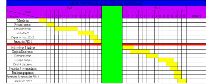
1.5 Project Planning
CHAPTER 2
LITERATURE REVIEW
2.1 Introduction
In this chapter, research and studies about this project will be implementation. Firstly, the basic explanation about water level is described. List of the equipment used in is described in the general way. Apart from that, the equipment that will be used is a flow sensor. Flow sensor is used for the project to detect the flow water at water level control training kit.
These chapters also include the control and the programming involved in the project. Program language such Visual Basic either one of type discovered at the chapter. In the end this chapter, design for water level training kit will be done with guide from the information.
2.2 Water Level Control
or more friendly user and easy to control. The equipment that used in this project such as:
2.2.1 Water Level Measurement
Water level measurement is used to measure level of water. Many type water level measurements can used to develop this project, such as:
2.2.1.1Flow Sensor
A flow sensor is a device that responds to fluid flow by providing an output indicative of the fluid flow rate. Flow sensors are utilized in a variety of fluid-sensing applications for detecting the quality of fluids, including gas and liquid. Normally a flow sensor is the sensing element used in a flow meter, or a flow data logging device. The flow sensor can normally measure velocity or flow rate. Flow sensors are sometimes related to sensors called velocity meters for measure speed of fluids that flowing. A flow sensor can work by direct measurement or inferential measurement. The flow sensor technology can be based on such things as light, heat, electromagnetic properties, ultrasonic and many other technologies in a wide spectrum.
2.2.1.2Flow Switch
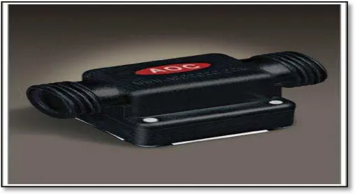
Fluid Flow switch sensing devices have been developed for monitoring fluid flow in pipelines or other ducts. A flow switch produces an electrical signal which is suitable with a preselected rate of flow of a fluid in a pipe. Various flow switches have been developed to be responsive to the flow rate of a fluid within a flow line. Usually the flow switch is connected into the flow line so that the flow path of the fluid passes through the flow switch. (www.omega.com)
Figure 2.1: flow switch
2.2.1.3Flow Meter
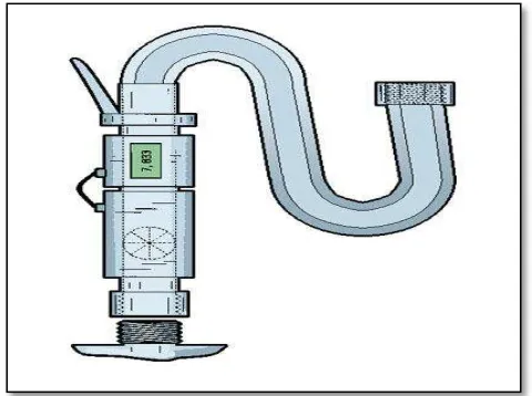
Measuring flow rate is an important requirement in many experimental and industrial applications. Flow meters are used for a variety of applications where it is desired to measure the flow rate or volume of a given fluid or gaseous material. The flow meter is an instrument used to measured linear, nonlinear, mass or volumetric flow rate of water. Determine the required meter range by identifying minimum and maximum flows that will be measured. After that, the required flow measurement accuracy is determined. Typically accuracy is specified in percentage of actual reading (AR), in percentage of calibrated span (CS), or in percentage of full scale (FS) units.
always a larger quantity than the calibrated span (CS), a sensor with a % FS performance will always have a larger error than one with the same % CS specification.
Flow meter is suitable to get a performance from both a full flow meter and a point sensor. Because point sensors do not look at the full flow, they read accurately only if they are inserting to a depth where the flow velocity is the average of the velocity profile across the pipe. Even if this point is carefully determined at the time of calibration, it is not likely to remain unmoved, since velocity profiles change with flow rate, viscosity, temperature, and other factors. (www.omega.com)
Figure 2.2: flow meter
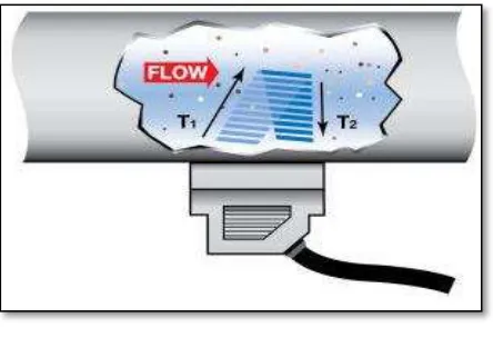
2.2.1.4 Ultrasonic flow
Ultrasonic flow uses to transfer time principle, where opposite sending and receiving transducers are used to transmit signal through the flow. The signal travel would be moving smoothly when according to correct flow. The difference time between the sending and receiving used to calculate the flow rate.
Figure 2.3: ultrasonic flow
2.2.2 Valve
Based on Deborah Anderson (2002), valves used to control the flow of water in a system, can be mechanical, hydraulic and electric. In order for a valve to work, there has to be a drop in pressure between the water source and the outlet, such as a sprinkler. The pressure drop enables the valve to close itself and an increase in pressure allows the valve to open. A problem can come up if there is a low flow of water, which does not create enough drops in pressure, so the drop in pressure has to be increased. This is accomplished by leaving the valve in question partially closed. Valves are used in a variety of contexts, including industrial, military, commercial, residential, and transport. The industries in which the majority of valves are used are oil and gas, power generation, mining, water reticulation, sewerage and chemical manufacturing.