UNIVERSITI TEKNIKAL MALAYSIA MELAKA
DESIGN AND ANALYSIS OF CASTING MOLD USING CAD
TOOL
This report submitted in accordance with requirement of the Universiti Teknikal Malaysia Melaka (UTeM) for the Bachelor Degree of Manufacturing Engineering
(Manufacturing Design) with Honours.
by
HOE LI SIM
i
DECLARATION
I hereby, declared this entitled “Design and Analysis of Casting Mold Using Cad Tool” is the results or my own research except as cited in references.
Signature : ………
Author‟s name : HOE LI SIM
ii
APPROVAL
This report is submitted to the faculty of Manufacturing Engineering of UTeM as a partial fulfillment of the requirements for the degree of bachelor of Manufacturing Engineering (Manufacturing Design) with Honours. The member of the supervisory committee is as follow:
……… Supervisor: MR. TAUFIK
iii
ABSTRACT
iv
ABSTRAK
Tajuk projek ini adalah Rekabentuk dan Analisis ke atas Acuan Tuangan Dengan Menggunakan Perisian CAD. Projek ini pada asasnya adalah bertujuan untuk mengkaji parameter tuangan acuan dan simulasi ke atas suhu dan tekanan acuan. Kompressor turbocharger dipilih sebagai produk teknik tuangan. Di antara jenis-jenis teknik tuangan, tuangan lilin hilang merupakan proses yang paling sesuai untuk menghasilkan produk tersebut. Alternatif rekabentuk acuan tuangan dihasilkan dengan menggunakan perisian CAD. Konsep penilaian dan penapisan telah disediakan untuk memilih rekean acuan yang paling sesuai untuk process tuangan lilin hilang. Pemilihan bahan untuk kompresor turbocharger ialah Aluminum Silicon Cardbide. Stainless steel AISI H13 pula dipilih sebagai bahan kepada acuan tersebt. Parameter rekaan acuan tersebut termasuk cabang, sistem aliran, corong dan aliran. Analisis ke atas acuan itu telah dilakukan dengan menggunakan perisian ANSYS
v
DEDICATION
This report is dedicated to my father and mother who have taught me that even the largest task
vi
ACKNOWLEDGEMENT
I would like to take this opportunity to express my highest gratitude and appreciation to my supervisor Mr. Taufik for continuing supports, supervises, encouragement, patience and constructive opinions throughout this project.
I am grateful for the cooperation and guidance which are given by my friends. First of all, I really appreciate the kindness of my friends who gave me so much important information about the project and willing to help me answering my entire question without hesitation.
vii
1.4 Scope And Key Assumption... 3
1.5 Organization Of The Report ... 3
1.7 Gantt Chart ... 5
CHAPTER2 LITERATUREREVIEW ... 7
2.1 Technology Of Casting ... 7
2.2 Defect Of Casting ... 10
2.3 Selection Of Casting Process ... 11
2.3.1 Metal Casting Process Comparison ... 11
2.4 Investment Casting ... 13
2.4.1 Block Mold Process ... 15
2.4.2 Ceramic Shell-Mold Process ... 16
2.4.3 Advantages Of Investment Casting ... 16
2.4.4 Disadvantages Of Investment Casting ... 17
viii
2.5.1 Types Of Sand Molds ... 19
2.5.2 Sand Casting Process ... 20
2.6 Material For Investment Casting Mold And Part ... 21
2.6.1 Material For Part ... 21
2.6.2 Material For Mold ... 22
2.6.2.1 Chromium-Molybdenum-Vanadium Alloyed Steel (Aisi H13) ... 25
2.7 Design Development ... 29
2.8.1 Heat Transfer Mechanism ... 34
2.8.2 Internal Energy ... 34
2.9 Design And Simulation Tool ... 35
2.9.1 Design Tool Solidworks ... 35
2.9.2 Analysis Tool Ansys ... 36
CHAPTER3 METHODOLOGY ... 38
3.1 Introduction ... 38
3.2 Methodology ... 38
3.3 Methodology Flow Chart... 39
3.4 Problem Analysis ... 40
3.5 Preliminary Design & Decision Analysis ... 40
3.5.1 Ideas Generation ... 41
3.5.2 Concept 1 ... 43
3.5.3 Concept 2 ... 44
3.5.4 Concept 2 ... 45
3.5.5 Concept Screening Matrix ... 46
3.5.5 Concept Scoring ... 47
3.6 Initial Concept Design Of Investment Casting Mold ... 48
3.6.1 Investment Casting Mold... 48
3.6.2 Assembly For Investment Casting Mold ... 49
ix
3.8 Investment Casting For Metal Mold ... 50
CHAPTER 4 DATA & RESULTS ... 52
4.1 Introduction ... 52
4.2 Simulation Analysis With Ansys Fluent ... 52
4.2.1 Create Geometry For The Gating ... 52
4.2.2 Create Mesh For Gating ... 53
4.3 Setup The Solver And Physical Models In Ansys Fluent ... 58
4.4 Result ... 63
4.5 Mold Design Proposed And Details Drawing ... 117
CHAPTER5 DISCUSSION ... 122
5.1 Comparison Between The Simulation Result ... 122
5.2 Investment Casting Mold Design ... 127
5.3 Advantages And Disadvantages Of Simulation Tool ... 127
CHAPTER6 CONCLUSION ... 128
6.1 Conclusion ... 128
6.2 Recommendations ... 129
REFERENCES ... 130
Appendix A: Technical Drawing ... 133
Appendix B: Investment Casting ... 137
Appendix C: Turbocharger ... 139
Appendix D: Rapid Prototyping ... 140
x
LIST OF TABLES
2.1 Characteristics of Casting Process 9 2.2 Overall score of Casting Process 13
2.3 Important Part of Sand Casting 19
2.4 Mechanical Properties of Aluminum Silicon Carbide 22 2.5 Physical Properties of Aluminum Silicon Carbide 22 2.6 Thermal Properties of Aluminum Silicon Carbide 22 2.7 Typical Tool and Die Material for the Metalworking 23 2.8 Basic Types of Tool and Die Steels 24 2.9 The Mechanical and Physical Properties of the Workpiece and Tool 25 2.10 Component Element Properties of AISI H13 26 2.11 Physical Properties of AISI H13 26 2.11 Processing Properties of AISI H13 26 2.13 Thermal Properties of AISI H13 27 2.14 Mechanical Properties of AISI H13 28
2.15 Concept Screening Matrix 32
2.16 Rating in Screening Matrix 32
2.17 Concept Scoring Matrix 33
2.18 Rating In Scoring Matrix 34
3.1 Concept Screening 46
3.2 Concept Scoring Matrix 47
4.1 Summary of Case 1(a) 71
xi
LIST OF FIGURES
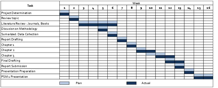
1.1 Gantt Chart of PSM 1 5
1.2 Gantt Chart of PSM 2 6
2.1 Hierarchical Classification of Various Casting Processes 8 2.2 Example of common defects in casting. These defects can be
minimized or eliminated by proper design and preparation of mold and control of pouring procedures 10 2.3 Capability to Cast Input “Quantity” for Different Metal Casting
2.6 Capability to Cast Input “Thin section” for Different Metal Casting Processes12
2.7 Capability to Cast Input “Surface finish” for Different Metal Casting
Processes 12
2.8 Schematic illustration of the investment casting (lost wax) process 14
2.9 Block Mold Process Flow 15
2.10 Ceramic Shell-Mold Process Flow 16 2.11 Outline of Production Steps in A Typical Sand-Casting Operation 18 2.12 Schematic Illustration of a Sand Mold, Showing Various Features 19 2.13 Schematic Illustration of the Sequence of Operations for Sand
Casting 21
2.14 The Five-Step Concept Generation Method 30 2.15 Example of Product Design by Using SolidWorks Tool 36
2.16 CFD Design Iteration 37
3.1 Methodology Flow Chart 39
xii
4.1 Geometry for Simulation by Using SolidWorks 53
4.2 Browsing 3D Model Geometry 54
4.3 Refresh Mesh 54
4.4 Update Mesh 54
4.5 Mesh Editing 55
4.6 Create Boundary Condition 55
4.7 Insert the Boundary Condition Name 55 4.8 Select the Related Surface for the Boundary Condition 56 4.9 Save Project and Close the Mesh Window 56 4.10 Meshing for the Geometry of the Mold 57 4.11 Meshing for the Geometry of Inlet and Gating 57 4.12 Meshing for the Geometry of Turbocharger 57 4.13 Update the Mesh for the Additional Information 58
4.14 ANSYS FLUENT Launcher 58
4.15 ANSYS FLUENT Window 59
4.16 Enable Energy Equation 59
4.17 Viscous Model Setting 60
4.18 Create Material Type for Fluid 60 4.19 Velocity Magnitude Setting for Velocity Inlet 61 4.20 Temperature Setting for Velocity Inlet 61 4.21 Select the Solution Initialize 62 4.22 Set the Number of Iteration and Start Running Calculation 62
4.23 Scaled Residuals 63
xiii
4.26 Velocity Vector Colored by Static Pressure for the Turbocharger
(Pascal) 65
4.27 Contours of Density for the Mold (kg/m2) 65 4.28 Velocity Vector Colored by Density for the Mold (kg/m2) 66 4.29 Velocity Vector Colored by Density for the Turbocharger(kg/m2) 66 4.30 Contours of Velocity Magnitude for the Mold (m/s) 67 4.31 Velocity Vector Colored by Velocity Magnitude for the Mold (m/s) 67 4.32 Velocity Vector Colored by Velocity Magnitude for the
Turbocharger (m/s) 68
4.33 Contours of Static Temperature for the Mold (K) 68 4.34 Velocity Vector Colored by Static Temperature for the Mold (K) 69 4.35 Velocity Vector Colored by Static Temperature for the Turbocharger
(K) 69
4.36 Contours of Turbulence Kinetic Energy for the Mold (m2/s2) 70 4.37 Velocity Vector by Turbulence Kinetic Energy for the Mold (m2/s2) 70 4.38 Velocity Vector by Turbulence Kinetic Energy for the Turbocharger
(m2/s2) 71
4.39 Scaled Residuals 72
4.40 Contours of Static Pressure for the Mold (Pascal) 73 4.41 Velocity Vector Colored by Static Pressure for the Mold (Pascal) 73 4.42 Velocity Vector Colored by Static Pressure for the Turbocharger
(Pascal) 74
4.43 Contours of Density for the Mold (kg/m2) 74 4.44 Velocity Vector Colored by Density for the Mold (kg/m2) 75 4.45 Velocity Vector Colored by Density for the Turbocharger (kg/m2) 75 4.46 Contours of Velocity Magnitude for the Mold (m/s) 76 4.47 Velocity Vector Colored by Velocity Magnitude for the Mold (m/s) 76 4.48 Velocity Vector Colored by Velocity Magnitude for the
Turbocharger (m/s) 77
4.49 Contours of Static Temperature for the Mold (K) 77 4.50 Velocity Vector Colored by Static Temperature for the Mold (K) 78 4.51 Velocity Vector Colored by Static Temperature for the Turbocharger
(K) 78
xiv
4.53 Velocity Vector by Turbulence Kinetic Energy for the Mold (m2/s2) 79 4.54 Velocity Vector by Turbulence Kinetic Energy for the Turbocharger
(m2/s2) 80
4.55 Scaled Residuals 81
4.56 Contours of Static Pressure for the Mold (Pascal) 82 4.57 Velocity Vector Colored by Static Pressure for the Mold (Pascal) 82 4.58 Velocity Vector Colored by Static Pressure for the Turbocharger
(Pascal) 83
4.59 Contours of Density for the Mold (kg/m2) 83 4.60 Velocity Vector Colored by Density for the Mold (kg/m2) 84 4.61 Velocity Vector Colored by Density for the Turbocharger (kg/m2) 84 4.62 Contours of Velocity Magnitude for the Mold (m/s) 85 4.63 Velocity Vector Colored by Velocity Magnitude for the Mold (m/s) 85 4.64 Velocity Vector Colored by Velocity Magnitude for the
Turbocharger (m/s) 86
4.65 Contours of Static Temperature for the Mold (K) 86 4.66 Velocity Vector Colored by Static Temperature for the Mold (K) 87 4.67 Velocity Vector Colored by Static Temperature for the Turbocharger
(K) 87
4.68 Contours of Turbulence Kinetic Energy for the Mold (m2/s2) 88 4.69 Velocity Vector by Turbulence Kinetic Energy for the Mold (m2/s2) 88 4.70 Velocity Vector by Turbulence Kinetic Energy for the Turbocharger
(m2/s2) 89
4.71 Scaled Residuals 90
4.72 Contours of Static Pressure for the Mold (Pascal) 91 4.73 Velocity Vector Colored by Static Pressure for the Mold (Pascal) 91 4.74 Velocity Vector Colored by Static Pressure for the Turbocharger
(Pascal) 92
xv
4.80 Velocity Vector Colored by Velocity Magnitude for the
Turbocharger (m/s) 95
4.81 Contours of Static Temperature for the Mold (K) 95 4.82 Velocity Vector Colored by Static Temperature for the Mold (K) 96 4.83 Velocity Vector Colored by Static Temperature for the
Turbocharger (K) 96
4.84 Contours of Turbulence Kinetic Energy for the Mold (m2/s2) 97 4.85 Velocity Vector by Turbulence Kinetic Energy for the Mold (m2/s2)
97 4.86 Velocity Vector by Turbulence Kinetic Energy for the
Turbocharger (m2/s2) 98
4.87 Scaled Residuals 99
4.88 Contours of Static Pressure for the Mold (Pascal) 100 4.89 Velocity Vector Colored by Static Pressure for the Mold (Pascal) 100 4.90 Velocity Vector Colored by Static Pressure for the Turbocharger
(Pascal) 101
4.91 Contours of Density for the Mold (kg/m2) 101 4.92 Velocity Vector Colored by Density for the Mold (kg/m2) 102 4.93 Velocity Vector Colored by Density for the Turbocharger (kg/m2) 102 4.94 Contours of Velocity Magnitude for the Mold (m/s) 103 4.95 Velocity Vector Colored by Velocity Magnitude for the Mold(m/s) 103 4.96 Velocity Vector Colored by Velocity Magnitude for the
Turbocharger (m/s) 104
4.97 Contours of Static Temperature for the Mold (K) 104 4.98 Velocity Vector Colored by Static Temperature for the Mold (K) 105 4.99 Velocity Vector Colored by Static Temperature for the
Turbocharger (K) 105
4.100 Contours of Turbulence Kinetic Energy for the Mold (m2/s2) 106 4.101 Velocity Vector by Turbulence Kinetic Energy for the Mold (m2/s2)
106 4.102 Velocity Vector by Turbulence Kinetic Energy for the
Turbocharger (m2/s2) 107
4.103 Scaled Residuals 108
xvi
4.105 Velocity Vector Colored by Static Pressure for the Mold (Pascal) 109 4.106 Velocity Vector Colored by Static Pressure for the Turbocharger
(Pascal) 110
4.107 Contours of Density for the Mold (kg/m2) 110 4.108 Velocity Vector Colored by Density for the Mold (kg/m2) 111 4.109 Velocity Vector Colored by Density for the Turbocharger (kg/m2) 111 4.110 Contours of Velocity Magnitude for the Mold (m/s) 112 4.111 Velocity Vector Colored by Velocity Magnitude for the Mold (m/s)
112 4.112 Velocity Vector Colored by Velocity Magnitude for the
Turbocharger (m/s) 113
4.113 Contours of Static Temperature for the Mold (K) 113 4.114 Velocity Vector Colored by Static Temperature for the Mold (K) 114 4.115 Velocity Vector Colored by Static Temperature for the
Turbocharger (K) 114
4.116 Contours of Turbulence Kinetic Energy for the Mold (m2/s2) 115 4.117 Velocity Vector by Turbulence Kinetic Energy for the Mold (m2/s2)
115
5.3 Contours Temperature in Different Velocity and Temperature 124 5.4 Contours Turbulence Kinetic Energy in Case 1(a) 125 5.5 Velocity Vector Colored by Temperature in Different Velocity and
xvii
LIST OF ABBREVIATIONS
AISI H13 - Chromium-Molybdenum-Vanadium Alloyed Steel
CAD - Computer Aid Design
CFD - Computational Fluid Dynamics
CFX - Advanced Computational Fluid Dynamics
STL - Stereolithography
1
CHAPTER 1
INTRODUCTION
1.1 Background
There is various manufacturing process to produce parts which is including machining, casting, joining, forming and shaping. Among these manufacturing processes, metal casting is the most effective to produce metal parts. Metal casting processes include sand casting, plaster casting, investment casting and etc. Each of the process has its own characteristics and application to meet specific engineering and services requirement.
According to Kasim, et al. (2008), manufacturing process selection is the task of choosing a method for transforming a set of material into a given shape using one or more processes. The material and manufacturing process selection problem is a multi-attribute decision-making problem. These decisions are made during the preliminary design stages in an environment characterized by and uncertain requirements, parameters, and relationships. Material and process selection decisions occur before design for manufacturing can begin.
2
According to Kalpakjian and Schmid (2006), metal casting technology was started before 4000 B.C. by using materials such as gold, copper and meteoric iron. Lost wax process which is known as investment casting was started around 4000 B.C to 3000 B.C. The technique of metal casting is keeping improved until nowadays to produce the best quality of metal product and to achieve public need and requirement.
For metal casting process, mold filling is the most important step in determining the quality of a casting. Surface quality, porosity caused by gas entrapment, misruns, micro segregation and mold erosion caused by strong metal streams. All these phenomena can be closely related to the mold filling condition. Therefore, mold life is also affected by mold filling. Although the solidification process appears to be of primary interest to the foundry engineer, solidification alone does not suffice for accurate prediction of casting quality refer to Attar et al. (2005).
A good design of mold will allow a smooth flow when filling. Therefore, mold design process is important to produce a better metal casting product. This study will carry out a casting mold design by using a CAD tool SolidWorks. The designation and the type of casting mold will be validated. The finite element analysis will be done on the mold. The analysis of heat transfer, temperature & pressure will be presented by using ANSYS. An automotive part, turbocharger impeller will be used as the product for the casting mold.
1.2 Problem Statement
3 1.3 Objectives
The objectives of this project are:
a) To investigate the design parameters in designing casting mold. b) To analyze the temperature and pressure in casting mold. c) To propose a design of investment casting mold.
1.4 Scope and Key Assumption
This project presents the design of casting mold using CAD tools. SolidWorks is used to perform the details drawing of the mold. The analysis of temperature and pressure is presented by using simulation ANSYS. As a result, the design of investment casting mold is proposed. Stainless steel H13 is selected as the material of the mold.
1.5 Organization of the Report
The whole report is divided into six major parts, which is known as Introduction, Literature Review, Methodology, Results, Discussion, and Conclusion. Each chapter is briefly such as below:
a) Chapter 1: Introduction
This chapter briefly describes about the background of the study, problem statement, the objectives and scopes of the project. In the end of this chapter, it summarized the whole project and Gantt chart of the project will be shown at the end of this chapter.
b) Chapter 2: Literature Review
4
to analysis it. The sources which are from journals, books, internet, articles and others are the guide to completing this project.
c) Chapter 3: Methodology
Methodology shows the flow of designing of the project. It starts from the problem analysis to the concept generation and concept selection and make the design decision. It is then following with the process of investment casting mold to produce the turbocharger.
d) Chapter 4: Results
In this chapter, the analysis of the mold is presented which is including temperature and pressure of the selected mold. At the end of the process, the design parameter is defined and an investment casting mold is proposed.
e) Chapter 5: Discussion
This chapter generally discusses on the result of the finding and implicate of the project. The finding is comparing to the objectives of the project whether it cover the scope of the study.
f) Chapter 6: Conclusion
5 1.7 Gantt Chart
Gantt chart is built to show the sequence of the project flow and activities. Figure 1.1 such as below shows the Gantt chart for PSM 1 which is briefly shows the time taken to finish the task in completing the project.
Figure 1.1: Gantt Chart of PSM 1.
1 2 3 4 5 6 7 8 9 10 11 12 13 14 15 16
Project Determination Review topic
Plan Actual
Presentation Preparation
PSM 1 Presentation Chapter 1
Chapter 2 Chapter 3 Final Drafting Report Submission
Literature Review : Journals, Books
Discusion on Methodology Sumarized: Data Collection Report Drafting
Task