DESIGN OF DUAL BAND FREQUENCY SELECTIVE
SURFACE
NORSHAHIDA BINTI MOHD SAIDI
B071110042
UNIVERSITI TEKNIKAL MALAYSIA MELAKA
UNIVERSITI TEKNIKAL MALAYSIA MELAKA
DESIGN OF DUAL BAND
FREQUENCY SELECTIVE SURFACE (FSS)
This report submitted in accordance with requirement of the Universiti Teknikal Malaysia Melaka (UTeM) for the Bachelor’s Degree in Electronics Engineering
Technology (Telecommunications) with Honours
by
NORSHAHIDA BINTI MOHD SAIDI B071110042
920502025622
UNIVERSITI TEKNIKAL MALAYSIA MELAKA
BORANG PENGESAHAN STATUS LAPORAN PROJEK SARJANA MUDA
TAJUK: DESIGN OF DUAL BAND FREQUENCY SELECTIVE SURFACE
SESI PENGAJIAN: 2014/15 SEMESTER 1
Saya: NORSHAHIDA BINTI MOHD SAIDI
mengaku membenarkan Laporan PSM ini disimpan di Perpustakaan Universiti Teknikal Malaysia Melaka (UTeM) dengan syarat-syarat kegunaan seperti berikut:
1. Laporan PSM adalah hak milik Universiti Teknikal Malaysia Melaka dan penulis. 2. Perpustakaan Universiti Teknikal Malaysia Melaka dibenarkan membuat salinan
untuk tujuan pengajian sahaja dengan izin penulis.
3. Perpustakaan dibenarkan membuat salinan laporan PSM ini sebagai bahan pertukaran antara institusi pengajian tinggi. atau kepentingan Malaysia sebagaimana yang termaktub dalam AKTA RAHSIA RASMI 1972)
(Mengandungi maklumat TERHAD yang telah ditentukan oleh organisasi/badan di mana penyelidikan dijalankan)
Alamat Tetap:
NO 1A, PPRT KG SUNGAI NAMEK,
iv
DECLARATION
I hereby, declared this report entitled “Design of Dual Band Frequency Selective Surface” is the results of my own research except as cited in references.
Signature : ……….
Author’s Name : ………
v
APPROVAL
This report is submitted to the Faculty of Engineering Technology of UTeM as a partial fulfillment of the requirements for the Bachelor’s Degree in Electronics Engineering Technology (Telecommunications) with Honours. The member of the supervisory is as follow:
vi
ABSTRAK
'Frequency Selective Surface' (FSS) boleh dianggap sebagai pembinaan
vii
ABSTRACT
A Frequency Selective Surface (FSS) can be considered to be a surface construction serving as a filter for plane waves at any angles of incidence. It has been widely used in broadband communications, radar systems, and antenna technology. Today there is a growing demand on multifunctional antennas for telecommunication systems. Therefore the development of FSS with multiband characteristics is needed. The objective of this project is to design a dual band Frequency Selective Surface (FSS) by using certain frequency to obtain FSS with excellent performance by choosing a suitable element or combinations of elements. The technique used to achieve dual band FSS is by using Double Square loop structure because the square loop has the advantages which are simple in structure and easy to analyse and fabricate with low cost materials and exhibits a low weight and easy to handle structure. Finally, the FSS was designed and simulated by using CST Studio Suite software at 8.0 GHz and 10.3 GHz resonant frequency.
viii
DEDICATION
To my beloved parents,
Mohd Saidi Bin Wahab and Ruseni Bt Mat Naam that have sacrificed so much and was always encouraging and support for the sake of your daughter to be beneficial
person to the society.
Without enduring the bone chilling cold,
ix
ACKNOWLEDGEMENT
Syukur Alhamdulillah, all praises are due to Allah, finally this project report come to an end. In order to complete this report, I was in contact with many people. They have contributed towards my understanding and thought.
x
CHAPTER 2: LITERATURE REVIEW
xi
2.7 Incident Angle 17
2.8 Research Studies 18
2.8.1 A Novel Dual Band FSS 19
2.8.2 Design of DSLFSS with Swarm Particle Optimization via the
Equivalent Circuit Model 20
2.8.3 The Study of Dual Band Frequency Selective Surface with
Miniaturized Element in Low Frequency 21
2.9 Conclusion 22
CHAPTER 3: METHODOLOGY
3.1 Introduction 23
3.1.1 Literature Review 23
3.1.2 Data Collection 24
3.1.3 Design and Simulation 24
3.1.4 Fabricate and Hardware Test 24
3.1.5 Documentation 24
3.2 Flowchart 25
3.3 FSS Modelling and Simulation 27
3.3.1 Simulation Software 27
3.3.2 Simulation by using CST 27
3.4 FSS Model 29
3.5 Development Prototype of FSS 31
3.5.1 FSS Fabrication 31
3.5.2 Measurement Setup 34
3.6 Conclusion 36
CHAPTER 4: RESULT AND DISCUSSION
4.1 Simulation Result 37
4.1.1 Transmission and Reflection curve of DSLFSS 38
4.1.2 Effect of Varying Length of Element 39
4.1.3 Effect of Varying Element Width 40
xii
4.2 Free Space Measurement 42
4.3 Result Comparison 43
4.4 Conclusion 45
CHAPTER 5: CONCLUSION AND FUTURE WORK
5.1 Project Conclusion 46
5.2 Future Work 47
REFERENCES 48
APPENDICES
xiii
LIST OF TABLES
2.1 Performance analysis of FSS’s different elements 15
3.1 Parameters of Square Loop FSS 28
4.1 Lab measurement results summary 43
xiv
LIST OF FIGURES
2.1 Types of FSS 6
2.2 Schematic representation of band stop and band pass FSS 6 2.3 Example of band stop FSS with dipole like metallic patches 7
2.4 Equivalent Circuit FSS 8
2.5 NASA DSS 13 beam-waveguide antenna and Cassegrain sub
reflector 10
2.6 FSS radomes integrated in airplanes and radomes for abroad
military ships 11
2.7 N-Poles 13
2.8 Loop Types 13
2.9 Plate Type 14
2.10 Combinations 14
2.11 Effects of dielectric on resonance frequency 17
2.12 Equivalent projected separation between elements by an obliquely incident signal
18
2.13 Overview of the whole unit. 19
2.14 Simulated reflection and transmission coefficients of the proposed FSS
3.5 FSS prototype fabrication process 31
3.6 Measurement Setup 34
4.1 Transmission and reflection response result 38
4.2 The effect of varying element length 39
4.3 The effect of varying element width 40
xv
4.5 Free space measurements 42
4.6 Transmission and Reflection response result 43
xvi
LIST OF ABBREVIATIONS, SYMBOLS AND
NOMENCLATURE
CST - Computer Simulation Technology DSL - Double Square Loop
RFID - Radio Frequency Identification
RX - Receiving Antenna
TX - Transmitting Antenna
S11 - Reflector Coefficient S21 - Transmission Coefficient
f - Frequecy
BW - Bandwidth
� - Theta
1 This chapter discussed about the introduction of this project such as general information about Frequency Selective Surface (FSS), problem statement, objective, scope of the project and explanation organization of project.
1.1 Project Background
Since early 1960’s, due to applications military potential, structures FSS has being intensive study matter. Marconi and Franklin, however are believed, to becoming early pioneer in this area for their contribution of a parabolic reflection made using half-wavelength wire sections in 1919. FSS as frequency selective materials have traditionally used in stealth technology to reduce radar cross section (RCS) communication system.
The use of frequency selective surface (FSS) has successfully proven as a means to enhance communication capabilities satellite platform. In space missions such as Voyager, Galileo, and Cassini, the use of a dual-reflector antenna with FSS sub reflectors has made it possible to share the main reflector among different frequency band. Furthermore, growing demand in on multifunctional antenna for communication systems has required the development of FSS with features multiband.
INTRODUCTION
2 FSS structures to space waves are the counterparts of filters in transmission lines. Once revealed to electromagnetic radiation, FSS behaves like a spatial filter which is some frequency bands are transmitted and some are reflected. In a manner, FSS could be envelope because hide communication facilities. This may be first potential application FSS structures, because they had actually once used as coverage called radomes.
Thus, in some applications, the use of filters the signal is very important to get only the necessary signals from space. This is where the use of Frequency Selective Surface (FSS) becomes important. Use of FSS is to reduce interference between the signals and also acts as a filter signal. It only allows the signals required to pass through a given surface and reflects all any other unwanted signals into the air.
1.2 Problem Statement
3
1.3 Objective
The objectives of this project are:
1. To design of dual band Frequency Selective Surface by using certain frequency to obtain FSS with excellent performance by choosing a suitable element or combinations of elements.
2. To design the FSS by using CST software that offers accurate, efficient computational solutions for the hardware developing for this project.
1.4 Scope of Project
4
1.5 Project Overview
This report is organized into five chapters. For the first chapter, it is briefly discussed about the project background, the problem statement, the objective of this project and also the working scope for this project.
For the Chapter 2, the literature review was conducted throughout the entire project to gain knowledge and skills needed to complete this project. The main sources for this project are the previous projects and thesis that related to this project. And other sources are books, journals and articles obtained from the internet.
As for Chapter 3, this chapter brief the most important step in the design process of a desired FSS is the proper choice of constituting elements for the array. So in this chapter, it provides brief description the flow the design of dual band FSS consists of the most important part in the design FSS which is the elements of design and the elements geometries of FSS. All the steps taken to design the proposed FSS will be explained.
In Chapter 4, it is discussed about the simulation result from software and measurement result which is a dual-band frequency selective surface was designed, fabricated and measured with perfectly double square loop patch elements. The measurement results are compared with the simulation results obtained.
5 The literature review was conducted throughout the entire project to gain the knowledge and skills needed to complete this project. The main source for this project is the previous project and thesis related to this project and other sources are books, journals and articles obtained from the internet. In order to design this dual band of FSS, research had been made among previous project to studying the concept use, their method, making the best comparison and then implement in this project.
2.1 FSS Theory
Frequency Selective Surface, FSS are periodic surfaces that behave as filter for electromagnetic wave. FSS is a mounting structure that behaves similar plane as filter EM [1]. FSS can also be defined as a metal surface designed to be frequency selective in nature indicating it’s reflected or transmitted [6]. The frequency selective property described by Rittenhouse [3] proved the fact that surfaces can exhibit different transmission properties for different frequencies of incident wave. Based on geometries, FSSs can be categorized into four type of filter which is stop, band-pass, low-pass and high-pass as shown in Figure 2.1. Filtering characteristics of EM mainly depends on the type and shape of the FSS elements.
LITERATURE REVIEW
6 Figure 2.1: (a) band stop (b) band pass (c) low pass (d) high pass. Conductive part
represent by brown color
Some types of FSS exist but they can be grouped into two main classes: band stop and band pass FSS. Both reached the behavior depends on their frequency resonance effects exploit periodic planar layout along the surface of the FSS own. In particular, the band stop FSS usually consists of several metal patch arbitrarily shaped printed on a dielectric substrate. Band pass FSS generally designed to create apertures in the metal plate. Both types of FSS can be formed by many layers stacked on top of each other.
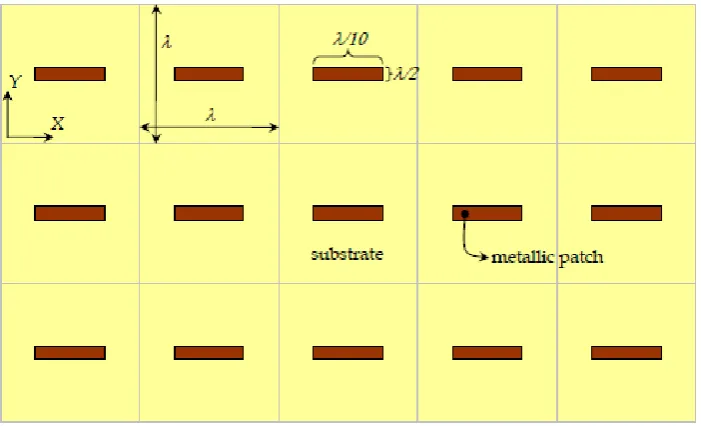
7 Due to the electromagnetic behavior of the FSS tied to a resonance phenomenon, a kind of band stop can achieve reflectance field incident despite the fact that the area covered by the metal is only a small part of the total area. Similarly, the type of band pass can achieve total transmission plane incident despite the fact that the apertures represents only a small fraction of the total area. To further realize the potential of these structures, the following simple example might help to give the proportion of resonance effects. Let's consider band stop FSS composed by metal patch shaped as dipoles, printed together on a regular layout on a dielectric substrate.
8
2.1.1 Equivalent Circuit FSS
Patch Element Aperture Element
Figure 2.4: Equivalent Circuit FSS
As shown in Figure 2.4, patch elements can be seen as a parallel connection of capacitors and inductors, and various elements of the aperture is represented by a series LC circuit, where the conducting element provides inductance and the distance between the elements represents capacitance. From this simple analysis, it is easy to show that the resonant frequency is given by:
Equation 2.1
The fractional bandwidth is defined as the difference between the lower and upper frequency at -10 dB which is proportional to
Equation 2.2