ANALYSIS OF HEAT TRANSFER IN PORTABLE POWER SUPPLY
AHMAD NAZRIN BIN ALI @ YUSOF
i
SUPERVISOR DECLARATION
“I hereby declare that I have read this thesis and in my opinion this report is sufficient in terms of scope and quality for the award of the degree of Bachelor of Mechanical
Engineering (Automotive)”
Signature: ………
ii
ANALYSIS OF HEAT TRANSFER IN PORTABLE POWER SUPPLY
AHMAD NAZRIN BIN ALI @ YUSOF
This thesis is submitted in partial fulfillment of the requirements for the Bachelor
of Mechanical Engineering (Automotive)
Faculty of Mechanical Engineering
Universiti Teknikal Malaysia Melaka
iii
DECLARATION
“I hereby declare that the work in this thesis is my own except for summaries and quotations which have been duly acknowledged.”
Signature: ………
iv
DEDICATION
v
ACKNOWLEDGEMENT
First of all, thank to God for giving me health, strength and opportunity to successfully completed Final Year Project. Eventhough there are few problems that I counter during conducting this project, but with God guidance and blessing, I finished my project.
I would like to thank to my beloved family especially my father and my mother, who’s always give motivation and never stop pray for my success. They are my light and the root for my strength.
I also would like to express my gratitude to my supervisor, Dr. Mohd Azman Abdullah, who greatly support and encourage me while conduct this project. He has generously spending his time and never stops giving guidance to me. Without him, I would never successfully complete this project.
vi ABSTRACT
vii ABSTRAK
viii
TABLE OF CONTENT
CHAPTER CONTENT PAGE
SUPERVISOR DECLARATION i
DECLARATION ii
DEDICATION iv
ACKNOWLEDGEMENT v
ABSTRACT vi
ABSTRAK viii
LIST OF CONTENTS vii
LIST OF TABLES xi
LIST OF FIGURES xiii
LIST OF SYMBOLS viii
LIST OF ABBREVIATIONS viii
LIST OF APPENDIX viii
CHAPTER 1 INTRODUCTION 1
1.1 Project Background 1
1.2 Problem Statement 2
1.3 Objectives 2
1.4 Scopes 3
ix
CHAPTER 2 LITERATURE REVIEW 4
2.1 Introduction 4
2.2 CFD Analyses of A Notebook Computer Thermal Management System
5
2.3 Exploring ANSYS Software 8
2.4 Pipe elbow Tutorial 10
2.4.1 Problem description 10
2.4.2 ANSYS FLUENT Workbench for pipe elbow 11
CHAPTER 3 METHODOLOGY 14
3.1 Introduction 14
3.2 Project Flow Chart 16
3.3 Portable Power Supply 17
3.4 ANSYS FLUENT Workbench 20
3.4.1 Geometry 21
3.4.2 Mesh 23
3.4.3 Setup solution 25
3.5 Experimental setup and procedure 30
3.5.1 Thermocouple position 30
3.5.2 PicoLog Recorder software setup 31
3.5.3 Experimental setup 32
CHAPTER 4 RESULT AND DISCUSSION 36
4.1 Introduction 36
4.2 Problem analysis 36
4.3 ANSYS Workbench result 37
4.3.1 CFD model analysis 39
4.4 Experimental data 40
x
CHAPTER 5 CONCLUSION 47
5.1 Conclusion 47
5.2 Recommendation 48
REFERENCES 49
xi
LIST OF TABLES
NO. TITLE PAGE
2.1 Heat dissipation values, average and hot spot temperatures of the components
7
2.2 Flow material properties 10
3.1 Specifications of Fan model 18
3.2 Model 1 and model 2 battery position 22
3.3 Properties of materials for each component 27
3.4 Boundary condition for model 1 and model 2 28
3.4 Boundary condition for model 3 29
4.1 Temperature inside PPS at 180 minutes during discharge 40 4.2 Temperature inside PPS at 180 minutes during charge 40
xii
LIST OF FIGURES
NO. TITLE PAGE
2.1 Computational domain 7
2.2 Series ANSYS FLUENT Architecture 9
2.3 Parallel ANSYS FLUENT Architecture 9
2.4 Pipe elbow specification with water properties 10
2.5 Contours of pressure for (a) water, (b) air and (c) kerosene 12 2.6 Contours of temperature for (a)water, (b) air and (c) kerosene 13
3.1 Flow chart 16
3.2 Portable power supply 17
3.3 3.4 3.5 3.6 3.7 3.8
Laptop cooler pad Sketch of the model 3
ANSYS FLUENT Workbench interface Model 1 Model 2 Model 3 18 19 21 22 22 23
3.9 Detail of Mesh 24
3.10 Generate meshing for model 24
3.11 Select and naming inlet for model 24
3.12 Naming each inlet/outlet and each components geometry 25
3.13 Model settings 26
3.14 Create abs-plastic material 27
3.15 Select abs-plastic material for casing 28
3.16 Run calculation 29
xiii
3.18 Insert channel 31
3.19 Sampling 31
3.20 Data collected 32
3.21 Experiment setup 33
3.22 Experiment inlet closed, outlet open 33
3.23 Experiment inlet open, outlet closed 34
3.24 Experiment inlet closed, outlet open 34
3.25 Experiment inlet fan, outlet open 35
3.26 Experiment inlet open, outlet fan 35
3.27 Experiment inlet fan, outlet fan 35
4.1 Pathlines of vector for (a) model 1, (b) model 2 37 4.2 Contours of heat for (a) model 1 and (b) model 2 37
4.3 Contour of heat for model 3 39
4.4 Experiment inlet closed, outlet closed for (a) Discharge, (b) Charge 42 4.5 Experiment inlet open, outlet closed for (a) Discharge, (b) Charge 42 4.6 Experiment inlet closed, outlet open for (a) Discharge, (b) Charge 42 4.7 Experiment inlet fan, outlet open for (a) Discharge, (b) Charge 43 4.8 Experiment inlet open, outlet fan for (a) Discharge, (b) Charge 43 4.9 Experiment inlet fan, outlet fan for (a) Discharge, (b) Charge 43 4.10 Comparison of temperature between CFD model 3 and experiment
inlet fan, outlet fan
xiv
LIST OF SYMBOLS
A = surface area
v = velocity
P = pressure
T = temperature
p = density
cp = specific heat
k = thermal conductivity
µ = viscosity
v = voltage
oC = celcius
xv
LIST OF ABBREVIATIONS
FYP Final Year Project
PSM Projek Sarjana Muda
CFD Computational Fluid Dynamic
Exp Experiment
CFM Cubic Feet Meter
CAD Computer-aided Design
DC Direct current
AC Alternative Current
PPS Portable Power Supply
IC, OC Inlet closed, outlet closed
IO, OC Inlet open, outlet closed
IC, OO Inlet closed, outlet open
IF, OO Inlet fan, outlet open
IO, OF Inlet open, outlet closed
xvi
LIST OF APPENDIX
APPENDIX CONTENT PAGE
A Pipe elbow procedure 51
B Gantt Chart FYP 1 54
C Gantt Chart FYP 2 55
D Fan blower measurement 56
E Experimental 57
1 CHAPTER 1
INTRODUCTION
1.1 PROJECT BACKGROUND
2
1.2 PROBLEM STATEMENT
Portable power supply is machine that can be very useful to human. Consumers can get electrical power supply anywhere and anytime they want. This product focuses on green technology which uses battery that can recharge by the solar energy. But, the problem is the battery inside the product become hotter while being used or being charger. There is temperature limit for each component inside portable power supply to function properly. The increment of the temperature inside the machine could cause the machine to failure or damage and make it not safe to be used. CFD model are develop to study the heat flow in portable power supply. There are few elements that being used as manipulate variable such as battery position, window position and the present of blowing fan in order to optimize thermal performance and improve the reliability of the product. Besides that, experiment also will be conducted during this project in order to study heat flow in PPS thoroughly.
1.3 OBJECTIVE
3
1.4 SCOPE
There are four scopes need to be done for this project. The first one is develop CFD model by using ANSYS software. Second, use few elements as manipulated variable such as battery position and fan blower present while setup the parameter. Another scope is conducted the experiment that use inlet, outlet hole and fan present as manipulated variable. The last scope for this project is study and analysis heat flow of portable power supply.
1.5 THESIS OUTLINE
4 CHAPTER 2
LITERATURE REVIEW
2.1 INTRODUCTION
5
2.2 CFD ANALYSES OF A NOTEBOOK COMPUTER THERMAL
MANAGEMENT SYSTEM
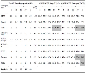
According to Tari and Yalzin (2010), the increasing energy costs and consumer awareness on environmental issues together with the advances in related electronic components shifted the demand in the personal computer industry towards notebook computers which have low energy consumption and less noise compare to desktops. But, due to the compact chassis, thermal management of a notebook is more difficult than a desktop. Heat dissipation to ambient air from a typical desktop computer can be easily achieved using forced convection due to greater air volume inside the chassis for circulation and large chassis surface area for placing the vents and fans. This is different for notebook computer which should be small as possible in term of size and weight. Therefore, there is not much space left inside chassis among the components that are placed very tightly. Every electronic component produce heat while operate and each electronic components has their own maximum allowable operating temperature. For notebook computer, CPU is the main heat source and produce most of heat among others component. But, even the smallest heat dissipation should be considered, because the components are packed together inside the chassis very tightly and component temperatures depend on all heat sources that produced. It is important to optimize thermal management to avoid machine failure and increase the reliability of the machine.
6
modeled according to measured dimensions. The components with little effect on the fluid flow and heat transfer are not modeled. Plus, there are two fans in the system, the first one is Fan 1 used to provide airflow to the fin-tube type remote heat exchanger (RHE) and the second one is Fan 2 that attached to an aluminum heat dissipation plate on the graphics chip and south bridge. The RHE is attached to the condenser ends of two heat pipes which transfer heat from the heat sink attached to the CPU. The heat pipes are represented as the solid rods having the same physical dimensions with the actual heat pipes and a high thermal conductivity in the axial direction taken as 40000 W/m.K.
7
Figure 2.1: Computational domain (Tari and Yalzin ,2010)
[image:24.595.170.468.380.632.2]