NATIONAL GUIDELINES FOR DIGITAL CAMERA SYSTEMS CERTIFICATION
Yaron Felus a, Eran Keinan a, Moshe Benhamu a, Ronen Regev a and Garry Zalmanzon b a
Survey of Israel, Lincoln 1, Tel-Aviv, 61141- (felus, eran, bhmoshe, ronenr)@ mapi.gov.il b
LMY R&D Ltd, 21 Bar Kochva St, Bene Beraq, 5126001- [email protected]
Commission I, WG I/3
KEY WORDS: Mapping standards, camera calibration, accuracy guidelines, digital photogrammetric sensor, photogrammetric test field, radiometry, spatial resolution.
ABSTRACT:
Digital camera systems are a key component in the production of reliable, geometrically accurate, high-resolution geospatial products. These systems have replaced film imaging in photogrammetric data capturing. Today, we see a proliferation of imaging sensors collecting photographs in different ground resolutions, spectral bands, swath sizes, radiometric characteristics, accuracies and carried on different mobile platforms. In addition, these imaging sensors are combined with navigational tools (such as GPS and IMU), active sensors such as laser scanning and powerful processing tools to obtain high quality geospatial products. The quality (accuracy, completeness, consistency, etc.) of these geospatial products is based on the use of calibrated, high-quality digital camera systems.
The new survey regulations of the state of Israel specify the quality requirements for each geospatial product including: maps at different scales and for different purposes, elevation models, orthophotographs, three-dimensional models at different levels of details (LOD) and more. In addition, the regulations require that digital camera systems used for mapping purposes should be certified using a rigorous mapping systems certification and validation process which is specified in the Director General Instructions.
The Director General Instructions for digital camera systems certification specify a two-step process as follows:
1. Theoretical analysis of system components that includes: study of the accuracy of each component and an integrative error propagation evaluation, examination of the radiometric and spectral response curves for the imaging sensors, the calibration requirements, and the working procedures.
2. Empirical study of the digital mapping system that examines a typical project (product scale, flight height, number and configuration of ground control points and process). The study examine all the aspects of the final product including; its accuracy, the product pixels size on the ground (spatial resolution), its completeness (missing pixels and striping affect), its radiometric properties (e.g., relative edge response) and its spectral characteristics (e.g., histogram spread, bands misalignment).
This methodology was tested on a number of medium to large format digital cameras. The certification process is a basic stage in the mapping chain in Israel. This article provides the details of the Director General Instructions for digital camera systems certification, the methodology for certification and the tests that were carried out.
1. INTRODUCTION
The Israeli requirements for digital photogrammetric camera system validation, calibration and certifications are described in Israeli Survey Regulations of 2016. The main goal of these regulations is to determine the following questions:
1. Can a specific camera system be used for a given mapping purpose (e.g.; constructions-permit map- 1:250, detailed design map 1:500, city plan 1:1000 etc.)? 2. If the answer to question 1 is yes, what would be the configuration of the aerial photography (number and distribution of control points, flight height, data processing chain, etc.)
Mapping and surveying procedures and technologies have been regulated in Israel since 1929 when the British Mandate enacted the Survey Ordinance. This Ordinance necessitate the publication of the Survey Regulations as the official document that defines and regulates the surveying work and the publication of the Director General Instructions that provide the technical details about the methodology and technologies (Felus et al. 2013).
The Israeli Survey Regulations of 2016 have been recently approved by the Minister of Construction and Housing and include new definitions for mapping products, new requirements for quality (accuracy and content) of these products and an update of the procedures, methods and technologies that can be used to derive these mapping products. These regulations also provide the details on the use of digital mapping platforms including the validation, calibration and certifications of these platforms.
The issue of digital photogrammetric camera system validation, calibration and certification has been investigated and reported in many articles. Cramer and Haala (2010) and Cramer et al (2010) described a comprehensive project for the empirical investigation of the performance of digital photogrammetric airborne cameras under the umbrella of the German Society of Photogrammetry, Remote Sensing and Geoinformation (DGPF). This project includes empirical test flights in the test field Vaihingen/Enz and a through evaluation of the sensor geometric performance. The evaluation included calculations of RMS error for various triangulations with varying set-up (number and distribution) of ground control points.
Honkavaara et al (2013) and Hanusch and Baltsavias (2009) investigated the radiometric aspects of digital photogrammetric airborne cameras including: histogram analysis, detection of artifacts (e.g. saturation, blooming, interlacing, compression), analysis of the vignetting effects, noise analysis, spectral response and linearity of the sensor.
Many other papers report on innovative calibration methods for digital cameras. Sampath et al (2012) developed methods for self-calibration of commercial of the shelf cameras with short focal length. Gneeniss et al (2015) described the use of complementary Lidar to validate and calibrate camera parameters. All these articles demonstrate the fact that camera certification is a topic of an ongoing research in which there are many unknowns and there are no common practices and standards yet to certify these technologies.
This article presents a practical approach that was taken in Israel to certify digital photogrammetric camera systems. This approach analyse the system as a whole and include the flying platform, optical system, the navigation devices (GPS, IMU) and the embedded processing software. The next section of the article, provides the basic requirements of the Survey Regulation for mapping products, namely; location accuracy, completeness (content), thematic accuracy and consistency. Then, Section 3 describes the Director General Instructions for digital camera system certification. Section 4 concludes the report with a description of the tests that were carried out and further work will be carried out on the topic.
2. MAPPING AND GEO-INFORMATION REGULATIONS IN ISRAEL
The field of mapping and Geospatial Information is consistently changing with new concepts and technologies making it impossible to set comprehensive regulations that will be valid for long time. Thus it was decided that the regulations will cover the basic definitions of mapping products and principal quality requirement and will not describe to the details of the technological procedures. The Director General Instructions are more dynamic and will be modified to follow technological changes. The three most important concepts that set the framework for the new regulations in mapping and Geospatial Information were: the change into a compete digital environment and the importance of proper metadata, sound quality control procedures and enabling the use of emerging technologies and advanced mapping products.
2.1 Digital environment and metadata
The new regulations recognize the need to move away from paper maps with legend and specified scale to a digital spatial
database (map) with metadata and specified quality parameters. Each digital spatial database should be provided according to the Director General Instructions, which specify the layer structure, attributes fields, entity relationships and with a Metadata file. The Metadata file structure is specified in the Director General Instructions which are comparable to the ISO19115 standard.
2.2 Quality control procedures
The new regulations put emphasis on modern quality control procedures, which are based on the ISO19157 principles and quality components. The six quality components which are described in the ISO are: logical consistency, positional accuracy, completeness, thematic accuracy, temporal accuracy, and usability. The Survey Regulation describe the detail requirements for the first four quality components, where the last two components are used only rarely for unique projects. The four quality components are:
A. Logical consistency – describes the fidelity of the relationships in the data set and the level of conformance to the required computer format. The dataset is automatically tested to see that it meets the computer format, otherwise it is rejected. In addition, automated software checks are carried out to evaluate various logical consistency parameters, for example:
Within a thematic layer - topological rules (e.g., search for overshoots or undershoots),
Domain rules for database fields and attributes (e.g., elevations cannot be smaller than -1000 m ) Between proper thematic layers (e.g., unreasonable
intersection of building layer with road layer) B. Positional accuracy - an assessment of the accuracy of the
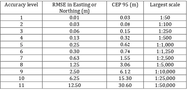
coordinates of spatial objects. The regulations' requirement's for accuracy are given as a function of the map level (scale) and presented in tables 1 and 2. Two measures are used as indicators for the accuracy the root mean square error (RMSE) and the CEP 95. RMSE is the square root of the average of the set of squared differences between dataset coordinate values and coordinate values from an independent source of higher accuracy for identical points. CEP 95 (circular error probability) is the radius of a circle, centered about the mean, whose boundary is expected to include locations of 95% of the measurements. These accuracy values are comparable to those in the ASPRS standard (ASPRS, 2014).
Table 1: Accuracy levels for mapping (horizontal)
Accuracy level RMSE in Easting or Northing (m)
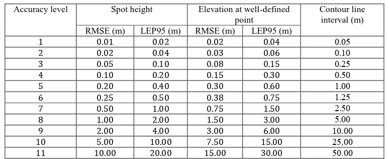
Table 2: Accuracy levels for mapping (vertical)
Accuracy level Spot height Elevation at well-defined point
Contour line interval (m) RMSE (m) LEP95 (m) RMSE (m) LEP95 (m)
. . . . 0.05
. . . . 0.10
. . . . 0.25
. . . . 0.50
. . . . 1.00
. . . . 1.25
. . . . 2.50
. . . . 5.00
. . . . 10.00
. . . . 25.00
. . . . 50.00
Table3: Ground Sample Distance for digital images (used in mapping and for ortho imagery)
C. Completeness – Is information about omissions, commissions and selection criteria within the data set. The new regulations specify the exact ground resolution of images and orthophotographs used for mapping at different levels, see Table 3.
With this limiting resolution, the regulations specify two selection criteria for the completeness parameter:
Every permanent object visible on the image, which covers an area greater than 36 times the ground resolution (at Table 3) should be mapped as a matter of routine.
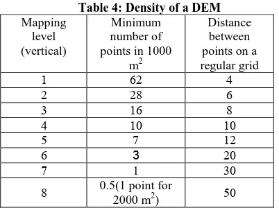
The Digital Terrain Model should include a breakline in every surface alteration larger than half the contour interval specified in Table 4.
Tests for to evaluate completeness are specified in the Director General Instruction and are carried out either by performing duplicate surveys by two different mapping organizations or by superimposition of the vector map on the screen with the raster image of the aerial photograph. Results will be reported in the same manner specified by ISO 19157.
D. Attribute Accuracy – is an assessment of the accuracy of the identification of entities and the assignment of attribute values in the data set.
This parameter is highly coupled with Completeness because both have similar tests. Results will be reported in the same manner specified by ISO 19157.
2.3 Enabling emerging technologies and advanced mapping products
One of the goals of the new regulation is to encourage the use of more efficient mapping procedures and technologies to produce more advanced mapping products.
Some of the latest mapping technologies include digital cameras (on satellites, aerial, on UAV's or on terrestrial systems), LIDAR, radar, mobile mapping systems. The regulations permit the use of any technology given that it was certified by the SOI as one that meets the quality requirements of a specific mapping level. Thus the regulations require that the SOI set up a certification program to test different sensors, and different combinations of integrated mapping platforms.
The regulation aims also at defining advanced mapping products that will be used to facilitate varying business activities (planning, design, construction, facility management, and more). Some of these include traditional products such as: Digital Elevation Model (DEM) - a regular grid of ground
points with spot heights, with density as described in table 4. Digital Terrain Model (DTM) – a DEM with natural and
artificial breaklines of the ground
Digital Surface Model (DSM) – a DTM with spot heights, elevation and breakline of earth's surface with all objects on it properly represented (building will have a rooftop breaklines as well as ground footprint breaklines).
Accuracy level 3 4 5 6 7 8 9
Maximal pixel size in cm 2.5 5.0 7.5 10.0 12.5 25.0 50.0
Surveying/
The Director General Instructions for quality determination of digital camera systems for mapping is based on the Survey Regulation requirements. Namely, given the accuracy requirements (in Tables 1 & 2) and the completeness specification the instructions detail the camera certification process. This process will have 5 stages as given in Figure 1:
Figure 1: Certification process
The first step is done by a surveying or mapping firm who fill a request for digital camera system certification. The request is a form that includes the following information:
A. Details of the optical system and the imaging sensor including: focal length, lens distortions, dynamic range, number of pixels, pixel size, GSD at 500m, field of view angles, alignment of the different camera heads to the Pan camera, geometric calibration using certified test stand, Modulation Transfer Function of each camera head, and frame rate.
B. Details of the sensor spectral properties including number of camera heads/ colour channels, PAN: colour resolution, spectral range of each channel (spectral graph), optical properties of each channel as given before.
C. Ancillary systems: type and description of each system such as IMU, GNSS, Gyro-Stabilized mount, and FMC D. Operating procedures and limitations including On-board storage, power consumption, operating temperature and altitude non pressurised
E. Software tools including a detailed description of all the software tools for flight planning, for image processing (compression, noise reduction, spectral and radiometric enhancement, etc.) and for positional determination (integrated triangulation)
F. Additional documents, policy of camera calibration, graph of the sensitivity of PAN camera, graph of relative spectral response, graph of sensor linearity, graph sensor noise, analysis of defect pixel etc.
G. Suggested plan for field testing
Using these documents the accredited certification institute evaluates the system and set the theoretical limits for the system accuracy and completeness i.e., the allowed map scale of the products (see step 2 in Figure 1). The certification institute carry on the field test of the system as will be described in section 3.2 and 3.3 and submit a recommendation report for the Survey of Israel. The report is analysed by the SOI managers and the camera is being ranked according to the accuracy level of the mapping products that it can produced. In the following two sections we will describe how the SOI measure the two criteria for ranking the quality of the map, i.e.; positional accuracy and completeness.
3.2 Positional Accuracy Testing
Tables 1 and 2 describe the accuracy requirements for mapping products with two measures: RMSE and CEP95. Accuracy requirements are at the 95% confidence level. This means that 95% of the positions in the mapping product will have an error with respect to true ground position that is equal to or smaller than the reported accuracy value. This is the underpinning assumption of the camera system certification testing. The tested camera will be flown over an area with marked ground control points at three different altitudes. Each altitude is suitable for a different mapping scale. Following a triangulation process, more than 50 well identified points are measured using the calculated stereo models. These points will be surveyed on the ground with precision DGPS. Both RMSE and CEP95 are computed and the camera is ranked according to Tables 1 and 2. In the beginning of the certification program, tests were carried out in a specialized test site in Tel-Aviv University. It was later determined that it is better to carry the tests in real-life projects selected by the mapping firm for three reasons:
1. The need to test the camera system in areas with large height differences (Cramer et al. 2010).
2. The needs to have an objective test were the check points are unknown to the mapping firm. The GCP coordinates are further transformed with unknown parameters to make sure that the triangulation is based only on these points.
3. Economic benefit to the company to have the test as part of their actual work. To the SOI it saves the cost of maintaining a test site.
An example for a test that was performed using this method is presented in Figure 2. Three strips of 11 images (total of 33 images) were flown with Z/I DMC II 140 camera at an altitude of 640m over Hedera in an area that covers 2.08 sq. km. The triangulation included 5 control points and 57 check points were measured on the ground. The camera was tested at 5 cm image resolution and with parameters that will allow it to produce a 1:500 maps or rank 4 accuracy. Details of the final certification report will be omitted for commercial reasons.
Figure 2: Test site in Hedara with 3 strips, 5 GCP and 57 check points
3.3 Completeness and Attribute Accuracy Testing
Mapping products should be complete and include all the topographic features that are required for the given map scale or accuracy ranking. To make the map complete the images used to produce them should be of apt quality. Many indicators have been developed to analyze the ability of an observer to perform map topographic features from images. The Johnson's criterion which was developed in the late 50's provides the minimum required resolution for a 50 percent probability of an observer discriminating an object to the specified level (Detection, Orientation, Recognition, and Identification where the specific object can be discerned). According to this criterion an interpreter should be able to identify a feature at a size of 12.8 +3.2/-2.8 pixels (Sjaardema et al 2015). This means for example that at a scale of 1:500 (rank 4) where the ground resolution is 5 cm (according to table 3) the interpreter should be able to identify features with length of 65 cm + 15 cm. These features lime these include: brick-tile, road center-line marking, fence lines, walls, manholes, stairs, road curb and storm drain, power boxes, etc.
Tests for image interpretability have been conducted for many years; a good example is the National Imagery Interpretability Rating Scale (NIIRS) was developed as a standardized measure of image interpretability (IRARS Committee, 1996).
The same approach is being conducted by the SOI, each image will be evaluated by expert interpreters to validate that features can be identified and mapped on the image using the specified resolution. For example, the certification process approves that the camera, flown at the specified altitude suitable for mapping products at rank 4 (1:500) since the expert interpreters identified features at a length greater than 65 cm +/- 15 cm (see Figure 3). The visual inspection also identity other defects and artifacts and display these in the report.
This visual inspection is costly as it required manual and time consuming examination by photogrammetric experts. The Survey of Israel is aiming at automating the process by using the approach of Kim et al (2010). Using this approach the General Image Quality Equation (GIQE) can predict Interpretability (NIIRS) as a function of Ground Sample. Distance (GSD), Relative Edge Response (RER), Signal-to-Noise (SNR), Convolver Gain (G), and Edge Overshoot (H). The equation is given by:
NIIRS = . – a × log GSD + b × log RER
+ . × H – . × G/SNR
Where a = 3.32 and b = 1.559 if RER ≥ 0.9 or a = 3.16 and b = 2.817 if RER < 0.9.
Figure 3: Tests for image interpretability (5cm resolution)
The SNR is computed by calculating the standard deviation of areas that have the same shade such as in figure 4. This can be also manmade features like crosswalk stripes on black asphalt
Figure 4: Test Target of uniform shades.
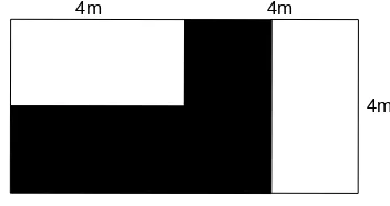
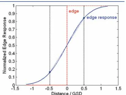
The RER is calculated by analyzing profiled of transactions from white to black in x and y directions (see Figure 5). On the profiles the normalized edge response values at points distances from the edge by -0.5 (ERx(-0.5)) and by 0.5 GSD are measured. The RER is then calculated by:
RER = [ERx . – ERx − . ]
× [ERy . – ERy − . ] ½; 4m 4m
4m
Figure 5: a profile used to calculate the relative edge response.
4. CONCLUSIONS AND FURTHER WORK
The Director General Instructions for quality determination of digital camera systems for mapping use a top-down approach for camera certification. Namely, given positional accuracy and completeness requirements, the Instructions'' process tests if the camera can meet those requirements with a given flight altitude and ground control points schema. The suggested flight altitude and ground control points schema for wide format cameras should be better than a standard analogue camera (focal length 152mm). The tests are based on simple procedures that do not require special test site, targets, and equipment and can be taken at any location.
Faced with the proliferation of camera systems -some mounted on UAV platforms - these procedures should be able to quickly and efficiently rank the systems and determine their quality. For this reason, the SOI is looking at automating the process of image quality determination using the GIQE, and automating the accuracy determination using an automatic comparison to orthophotographs with higher accuracy. These improvements can expedite the process which is going on (with 6 camera systems being tested) and strengthen the basic principles outlined in the Director General Instructions.
ACKNOWLEDGEMENTS
The authors would like to acknowledge the help of Amos Dror, Yohanan Gavish, Gili Kirschner, and David Glidayi for their assisted in developing the Director General Instructions. The help of Hetz Hazafon Company whose camera tests were partly presented in the paper is also appreciated.
REFERENCES
ASPRS (2014) ASPRS Positional Accuracy Standards for Digital Geospatial Data Ed. 1, Ver. 1.0. at
http://www.asprs.org/a/society/committees/standards/Positional _Accuracy_Standards.pdf
Cramer M., Grenzdörffer G. J., Honkavaara E. (2010), In situ digital airborne camera validation and certification—the future standard. International Archives of Photogrammetry, Remote Sensing and Spatial Information Sciences 01/2010; 38 At:
http://www.isprs.org/proceedings/XXXVIII/part1/08/08_04_Pa per_82.pdf
Cramer, M. and Haala, N. (2010): DGPF Project: Evaluation of digital photogrammetric aerial-based Imaging Systems –
Overview and Results from the Pilot Center, Photogrammetric Engineering & Remote Sensing Vol. 76, No. 9, September 2010, pp. 1019-1029
Felus Y., Keinan E., Regev R. (2013), Regulations in the field of Geo-Information, International Archives of the Photogrammetry, Remote Sensing and Spatial Information Sciences, Volume XL-7/W2, ISPRS2013-SSG, Turkey at:
http://www.int-arch-photogramm-remote-sens-spatial-inf-sci.net/XL-7-W2/87/2013/isprsarchives-XL-7-W2-87-2013.pdf
Gneeniss, A. S.; Mills, J. P.; Miller, P. E. (2015), In-flight photogrammetric camera calibration and validation via complementary lidar, ISPRS Journal of Photogrammetry and Remote Sensing, Vol. 100, February 2015, Pages 3–13 at:
http://www.sciencedirect.com/science/article/pii/S09242716140 01142
Hanusch, T. and Baltsavias, M. (2009), Evaluation of digital photogrammetric aerial camera systems– Radiometric evaluation of DMC, ADS40 and Ultracam-X, Annual Meeting of DGPF, at http://www.ifp.uni-stuttgart.de/dgpf/pdf/jt09-radiometrie-hanusch&baltsavias.pdf
Honkavaara E., Markelin L., Arbiol R., Martinez L. (2013), EuroSDR project: Radiometric Aspects of Digital Photogrammetric Images Final Report at
http://www.eurosdr.net/sites/default/files/uploaded_files/62_1.p df
IRARS Committee (1996) Civil NIIRS Reference Guide at:
http://fas.org/irp/imint/niirs_c/guide.htm
ISO (2013) ISO 19157 Geographic information -- Data quality at:
http://www.iso.org/iso/iso_catalogue/catalogue_tc/catalogue_de tail.htm?csnumber=32575
Kim T., Kim J., Kim D., Jeong J. (2010), Automated image interoperability assessment by edge profile analysis of natural targets, ASPRS 2010 Annual Conference. San Diego, California at:
http://www.asprs.org/a/publications/proceedings/sandiego2010/ sandiego10/Kim_T.pdf
Sampath, A., Moe, D., Christopherson, J. (2012), Two Methods for Self Calibration of Digital Camera, International Archives of the Photogrammetry, Remote Sensing and Spatial Information Sciences, Volume XXXIX-B1, 2012 XXII ISPRS Congress, Australia at: http://www.int-arch-photogramm-
remote-sens-spatial-inf-sci.net/XXXIX-B1/261/2012/isprsarchives-XXXIX-B1-261-2012.pdf
Sjaardema T.A, Smith C.S, and Birch G. C. (2015) History and Evolution of the Johnson Criteria, Sandia National Laboratories report at: http://prod.sandia.gov/techlib/access-control.cgi/2015/156368.pdf