NFPA 25
Standard for the
Inspection, Testing, and
Maintenance of Water-Based
Fire Protection Systems
1998 Edition
Copyright
National Fire Protection Association, Inc.
One Batterymarch Park
Quincy, Massachusetts 02269
IMPORTANT NOTICE ABOUT THIS DOCUMENT
NFPA codes, standards, recommended practices, and guides, of which the document contained herein is one, are
developed through a consensus standards development process approved by the American National Standards Institute.
This process brings together volunteers representing varied viewpoints and interests to achieve consensus on fire and other
safety issues. While the NFPA administers the process and establishes rules to promote fairness in the development of
consensus, it does not independently test, evaluate, or verify the accuracy of any information or the soundness of any
judgments contained in its codes and standards.
The NFPA disclaims liability for any personal injury, property or other damages of any nature whatsoever, whether
special, indirect, consequential or compensatory, directly or indirectly resulting from the publication, use of, or reliance
on this document. The NFPA also makes no guaranty or warranty as to the accuracy or completeness of any information
published herein.
In issuing and making this document available, the NFPA is not undertaking to render professional or other services for
or on behalf of any person or entity. Nor is the NFPA undertaking to perform any duty owed by any person or entity to
someone else. Anyone using this document should rely on his or her own independent judgment or, as appropriate, seek
the advice of a competent professional in determining the exercise of reasonable care in any given circumstances.
The NFPA has no power, nor does it undertake, to police or enforce compliance with the contents of this document.
Nor does the NFPA list, certify, test or inspect products, designs, or installations for compliance with this document. Any
certification or other statement of compliance with the requirements of this document shall not be attributable to the
NFPA and is solely the responsibility of the certifier or maker of the statement.
NOTICES
All questions or other communications relating to this document and all requests for information on NFPA procedures
governing its codes and standards development process, including information on the procedures for requesting Formal
Interpretations, for proposing Tentative Interim Amendments, and for proposing revisions to NFPA documents during
regular revision cycles, should be sent to NFPA headquarters, addressed to the attention of the Secretary, Standards
Council, National Fire Protection Association, 1 Batterymarch Park, P.O. Box 9101, Quincy, MA 02269-9101.
Users of this document should be aware that this document may be amended from time to time through the issuance of
Tentative Interim Amendments, and that an official NFPA document at any point in time consists of the current edition of
the document together with any Tentative Interim Amendments then in effect. In order to determine whether this
document is the current edition and whether it has been amended through the issuance of Tentative Interim
Amendments, consult appropriate NFPA publications such as the
National Fire Codes
Subscription Service, visit the NFPA
website at www.nfpa.org, or contact the NFPA at the address listed above.
A statement, written or oral, that is not processed in accordance with Section 5 of the Regulations Governing Committee
Projects shall not be considered the official position of NFPA or any of its Committees and shall not be considered to be,
nor be relied upon as, a Formal Interpretation.
The NFPA does not take any position with respect to the validity of any patent rights asserted in connection with any
items which are mentioned in or are the subject of this document, and the NFPA disclaims liability for the infringement of
any patent resulting from the use of or reliance on this document. Users of this document are expressly advised that
determination of the validity of any such patent rights, and the risk of infringement of such rights, is entirely their own
responsibility.
This document is copyrighted by the National Fire Protection Association (NFPA). By making this document available
for use and adoption by public authorities and others, the NFPA does not waive any rights in copyright to this document.
1. Adoption by Reference—Public authorities and others are urged to reference this document in laws, ordinances,
regulations, administrative orders, or similar instruments. Any deletions, additions, and changes desired by the adopting
authority must be noted separately. Those using this method are requested to notify the NFPA (Attention: Secretary,
Standards Council) in writing of such use. The term "adoption by reference" means the citing of title and publishing
information only.
2. Adoption by Transcription—A. Public authorities with lawmaking or rule-making powers only, upon written notice to
the NFPA (Attention: Secretary, Standards Council), will be granted a royalty-free license to print and republish this
document in whole or in part, with changes and additions, if any, noted separately, in laws, ordinances, regulations,
administrative orders, or similar instruments having the force of law, provided that: (1) due notice of NFPA's copyright is
contained in each law and in each copy thereof; and (2) that such printing and republication is limited to numbers
sufficient to satisfy the jurisdiction's lawmaking or rule-making process. B. Once this NFPA Code or Standard has been
adopted into law, all printings of this document by public authorities with lawmaking or rule-making powers or any other
persons desiring to reproduce this document or its contents as adopted by the jurisdiction in whole or in part, in any form,
upon written request to NFPA (Attention: Secretary, Standards Council), will be granted a nonexclusive license to print,
republish, and vend this document in whole or in part, with changes and additions, if any, noted separately, provided that
due notice of NFPA's copyright is contained in each copy. Such license shall be granted only upon agreement to pay NFPA
a royalty. This royalty is required to provide funds for the research and development necessary to continue the work of
NFPA and its volunteers in continually updating and revising NFPA standards. Under certain circumstances, public
authorities with lawmaking or rule-making powers may apply for and may receive a special royalty where the public interest
will be served thereby.
25–1
Copyright © 1998 NFPA, All Rights Reserved
NFPA 25
Standard for the
Inspection, Testing, and Maintenance of
Water-Based Fire Protection Systems
1998 Edition
This edition of NFPA 25, Standard for the Inspection, Testing, and Maintenance of Water-Based Fire Protection Systems, was prepared by the Technical Committee on Inspection, Testing, and Maintenance of Water-Based Systems and acted on by the National Fire Protection Associa-tion, Inc., at its Fall Meeting held November 17–19, 1997, in Kansas City, MO. It was issued by the Standards Council on January 16, 1998, with an effective date of February 6, 1998, and supersedes all previous editions.
NOTE: The text in Sections 1-2 and 2-3.1.3 was revised from that published in the Report on Proposals and the Report on Comments to reflect two Tentative Interim Amendments, issued by the Standards Council on January 15, 1998.
Changes other than editorial are indicated by a vertical rule in the margin of the pages on which they appear. These lines are included as an aid to the user in identifying changes from the previous edition.
This edition of NFPA 25 was approved as an American National Standard on April 2, 1998.
Origin and Development of NFPA 25
The first edition of NFPA 25 was a collection of inspection, testing, and maintenance pro-visions that help ensure the successful operation of water-based fire protection systems. NFPA 25 was developed as an extension of existing documents such as NFPA 13A, Recommended Prac-tice for the Inspection, Testing, and Maintenance of Sprinkler Systems, and NFPA 14A, Recommended Practice for the Inspection, Testing, and Maintenance of Standpipe and Hose Systems, which have suc-cessfully assisted authorities having jurisdiction and building owners with routine inspections of sprinkler systems and standpipes. These documents have since been withdrawn from the NFPA Standards System. NFPA 25 now governs sprinkler systems as well as related systems, including underground piping, fire pumps, storage tanks, water spray systems, and foam-water sprinkler systems.
This document provides instruction on how to conduct inspection, testing, and maintenance activities. It also stipulates how often such activities are required to be completed. Requirements are provided for impairment procedures, notification processes, and system restoration. This type of information, where incorporated into a building maintenance program, enhances the demonstrated favorable experience of all water-based fire protection systems.
The second edition incorporated several improvements that reflected the initial experi-ence with the standard. A new chapter was added that addresses obstructions in pipe as well as appropriate corrective actions.
Technical Committee on Inspection, Testing, and Maintenance of Water-Based Systems
William L. Testa, Chair
Grinnell Fire Protection Systems Co. Inc., RI [M] Rep. Nat’l Fire Sprinkler Assn.
Kenneth W. Linder, Secretary
Industrial Risk Insurers, CT [I]
Clement J. Adams, Chubb Group of Insurance Cos., PA [I] Gary S. Andress, Wausau HPR Engr, WI [I]
John K. Bouchard, Sedgwick James of New England, MA [I] Paul D. Brodeur, Falmouth Fire Dept., MA [E]
Walter A. Damon, Schirmer Engr Corp., IL [SE] Rep. TC on Fire Pumps
Manuel J. DeLerno, S-P-D Industries Inc., IL [M] Rep. Illinois Fire Prevention Assn.
David Dixon, Security Fire Protection, TN [IM] Rep. Nat’l Fire Sprinkler Assn.
James M. Fantauzzi, North East Fire Protection Systems Inc., NY [IM]
Rep. American Fire Sprinkler Assn., Inc. James M. Feld, Feld Engr, CA [SE]
Patricia J. Fisher, Premisys Real Estate., MA [U] Gary Gagnon, Alcan Aluminum Ltd, PQ, Canada [U] John K. Gillette, III, Denton Fire Dept., TX [E]
Rep. Int’l Fire Code Inst.
Christopher M. Goddard, Zeneca Inc., DE [U] Rep. TC Auto Sprin-NFPA/IFPS
Jon T. Harris, Nat’l Foam, Inc., PA [M]
William C. Harris, Fairbanks Morse Pump Corp., KS [M] Stephen R. Hoover, Kemper Nat’l Insurance Cos., IL [I]
Rep. TC Water Spray Fixed Systems
Richard Huff, Tomes, Van Rickley & Assoc., CA [U] Rep. The Home Depot
Larry Keeping, Vipond Automatic Sprinkler Co. Ltd, Ontario, Canada [IM]
Rep. Canadian Automatic Sprinkler Assn.
George E. Laverick, Underwriters Laboratories Inc., IL [RT] Raymond Lower, Cigna, WA [I]
Rep. American Insurance Services Group, Inc. Frank L. Moore, Moore Equipment Co., Inc., MS [IM] John D. Munno, Baltimore Gas and Electric Co., MD [U]
Rep. Edison Electric Inst.
M. G. Myers, Myers Risk Services, Inc., PA [SE] John F. Saidi, University of California, CA [U]
John J. Walsh, United Assn. of Journeymen & Apprentices of the Plumbing & Pipe Fitting Ind. of the U.S. & Canada, MD [L] William E. Wilcox, Factory Mutual Research Corp., MA [I]
Alternates
Kerry M. Bell, Underwriters Laboratories Inc., IL [RT] (Alt. to G. E. Laverick)
Eugene A. Cable, U.S. Dept. of Veterans Affairs, NY [U] (Voting Alt. to VA Rep.)
Larry J. Fronczak, Canadian Automatic Sprinkler Assn., Ontar-io, Canada [IM]
(Alt. to L. Keeping)
Joseph B. Hankins, Factory Mutual Research Corp., MA [I] (Alt. to W. E. Wilcox)
Kenneth E. Isman, Nat’l Fire Sprinkler Assn., NY [M] (Alt. to W. L. Testa)
Robert Martinelli, Kemper Nat’l Insurance Cos., MA [I] (Alt. to S. R. Hoover)
Jack A. Medovich, Virginia Sprinkler Co. Inc., MD [IM] (Alt. to J. M. Fantauzzi)
Richard Oliver, Oliver Sprinkler Co., Inc., PA [IM] (Alt. to D. Dixon)
Robert J. Pearce, Jr., Industrial Risk Insurers, CA [I] (Alt. to K. W. Linder)
J. William Sheppard, General Motors Corp., MI [U] (Voting Alt. to NFPA/IFPS Rep.)
Ralph Tiede, Wausau Insurance Cos., NY [I] (Alt. to G. S. Andress)
Barry J. Waterman, Acme Sprinkler Service Co., IL [M] (Alt. to M. J. DeLerno)
Robert A. Woodard, CIGNA Loss Control, PA [I] (Alt. to R. Lower)
Nonvoting
Thomas F. Norton, Norel Service Co., Inc., MA Rep. Nat’l Fire Alarm Code Committee
David R. Hague, NFPA Staff Liaison
This list represents the membership at the time the Committee was balloted on the text of this edition. Since that time, changes in the membership may have occurred. A key to classifications is found at the back of this document.
NOTE: Membership on a committee shall not in and of itself constitute an endorsement of the Association or any document developed by the committee on which the member serves.
CONTENTS 25–3
Contents
Chapter 1 General Information . . . 25– 4 1-1 Scope . . . 25– 4 1-2 Purpose . . . 25– 4 1-3 Water-Based Fire Protection System
Descriptions . . . 25– 4 1-4 Responsibility of the Owner or
Occupant‘ . . . 25– 5 1-5 Definitions . . . 25– 6 1-6 Units . . . 25–13 1-7 Impairments . . . 25–13 1-8 Records . . . 25–13 1-9 Inspection . . . 25–14 1-10 Testing . . . 25–15 1-11 Maintenance . . . 25–15 1-12 Safety . . . 25–15
Chapter 2 Sprinkler Systems . . . 25–15 2-1 General . . . 25–15 2-2 Inspection . . . 25–15 2-3 Testing . . . 25–17 2-4 Maintenance . . . 25–17
Chapter 3 Standpipe and Hose Systems. . . 25–19 3-1 General . . . 25–19 3-2 Inspection . . . 25–19 3-3 Testing . . . 25–19 3-4 Maintenance . . . 25–21 3-5 Records . . . 25–21
Chapter 4 Private Fire Service Mains . . . 25–21 4-1 General . . . 25–21 4-2 Inspection . . . 25–21 4-3 Testing . . . 25–23 4-4 Maintenance . . . 25–23 4-5 Records . . . 25–23
Chapter 5 Fire Pumps . . . 25–23 5-1 General . . . 25–23 5-2 Inspection . . . 25–24 5-3 Testing . . . 25–24 5-4 Reports . . . 25–26 5-5 Maintenance . . . 25–26
Chapter 6 Water Storage Tanks. . . 25–28 6-1 General . . . 25–28 6-2 Inspection . . . 25–28 6-3 Testing . . . 25–29 6-4 Maintenance . . . 25–30 6-5 Records . . . 25–30
Chapter 7 Water Spray Fixed Systems. . . 25–30 7-1 General . . . 25–30 7-2 Impairments . . . 25–32 7-3 Inspection and Maintenance
Procedures . . . 25–32 7-4 Operational Tests . . . 25–33 7-5 Ultra-High-Speed Water Spray System
Operational Tests . . . 25–34 7-6 Records . . . 25–34
Chapter 8 Foam-Water Sprinkler Systems. . . 25–34 8-1 General . . . 25–34 8-2 Inspection . . . 25–34 8-3 Operational Tests . . . 25–37 8-4 Maintenance . . . 25–38
Chapter 9 Valves, Valve Components, and Trim . . . . 25–39 9-1 General . . . 25–39 9-2 General Provisions . . . 25–39 9-3 Control Valves in Water-Based Fire
Protection Systems . . . 25–40 9-4 System Valves . . . 25–41 9-5 Pressure Reducing Valves and Relief
Valves . . . 25–43 9-6 Backflow Prevention Assemblies . . . 25–43 9-7 Fire Department Connections . . . 25–44
Chapter 10 Obstruction Investigation . . . 25–44 10-1 General . . . 25–44 10-2 Obstruction Investigation and
Prevention . . . 25–44 10-3 Prevention of Ice Obstruction . . . 25–44
Chapter 11 Impairments. . . 25–45 11-1 General . . . 25–45 11-2 Impairment Coordinator . . . 25–45 11-3 Tag Impairment System . . . 25–45 11-4 Impaired Equipment . . . 25–45 11-5 Preplanned Impairment Programs . . . 25–45 11-6 Emergency Impairments . . . 25–45 11-7 Restoring Systems to Service . . . 25–45
Chapter 12 Referenced Publications. . . 25–45
Appendix A Explanatory Material. . . 25–46
Appendix B Forms for Inspection, Testing, and
Maintenance. . . 25–70
Appendix C Referenced Publications. . . 25–102
NFPA 25
Standard for the
Inspection, Testing, and Maintenance of
Water-Based Fire Protection Systems
1998 Edition
NOTICE: An asterisk (*) following the number or letter des-ignating a paragraph indicates that explanatory material on the paragraph can be found in Appendix A.
Information on referenced publications can be found in Chapter 12 and Appendix C.
Chapter 1 General Information
1-1 Scope. This document establishes the minimum require-ments for the periodic inspection, testing, and maintenance of water-based fire protection systems, including land-based and marine applications. The types of systems addressed by this standard include, but are not limited to, sprinkler, stand-pipe and hose, fixed water spray, and foam water. Included are the water supplies that are part of these systems, such as pri-vate fire service mains and appurtenances, fire pumps and water storage tanks, and valves that control system flow. The document also addresses impairment handling and reporting. This standard applies to fire protection systems that have been properly installed in accordance with generally accepted prac-tices. Where a system has not been installed in accordance with generally accepted practices, the corrective action is beyond the scope of this standard. The corrective action to ensure that the system performs in a satisfactory manner shall be in accordance with the appropriate installation standard.
(See Chapter 12.)
Exception: This standard shall not apply to sprinkler systems de-signed and installed in accordance with NFPA 13D, Standard for the Installation of Sprinkler Systems in One- and Two-Family Dwellings and Manufactured Homes.
1-2* Purpose. The purpose of this document is to provide requirements that ensure a reasonable degree of protection for life and property from fire through minimum inspection, testing, and maintenance methods for water-based fire protec-tion systems.
In those cases where it is determined that an existing situa-tion can involve a distinct hazard to life or property, the authority having jurisdiction shall be permitted to require inspection, testing, and maintenance methods in excess of those required by the standard.
1-2.1* Application. It is not the intent of this document to limit or restrict the use of other inspection, testing, or mainte-nance programs that provide an equivalent level of system integrity and performance to that detailed in this document. The authority having jurisdiction shall be consulted and approval obtained for such alternative programs.
1-3 Water-Based Fire Protection System Descriptions.
1-3.1* Sprinkler System. An integrated system of under-ground and overhead piping designed for fire protection pur-poses and designed in accordance with fire protection engineering standards. The installation includes one or more automatic water supplies. The portion of the sprinkler system above ground is a network of specially sized or hydraulically designed piping installed in a building, structure, or area,
gen-erally overhead. Sprinklers are attached to the piping in a sys-tematic pattern. The valve controlling each system riser is located in the system riser or its supply piping. Each sprinkler system riser includes a device for actuating an alarm when the system is in operation. The system usually is activated by heat from a fire and discharges water over the fire area.
Wet Pipe System. A sprinkler system employing automatic sprinklers attached to a piping system containing water and connected to a water supply so that water discharges immedi-ately from sprinklers opened by heat from a fire. (See Chapters 2 and 9.) Hose connections [11/
2-in. (38.1-mm) hose, valves,
and nozzles] supplied by sprinkler system piping are consid-ered components of the sprinkler system.
Antifreeze System. A wet pipe system employing automatic sprinklers attached to a piping system containing an antifreeze solution and connected to a water supply. The antifreeze solu-tion is discharged, followed by water, immediately upon oper-ation of sprinklers opened by heat from a fire. (See Chapters 2 and 9.)
Dry Pipe System. A system employing automatic sprinklers attached to a piping system containing air or nitrogen under pressure, the release of which (as from the opening of a sprin-kler) allows the water pressure to open a valve known as a dry pipe valve. The water then flows into the piping system and out the opened sprinklers. (See Chapters 2 and 9.)
Deluge System. A system employing open sprinklers attached to a piping system and connected to a water supply through a valve that is opened by the operation of a detection system installed in the same areas as the sprinklers. When this valve opens, water flows into the piping system and discharges from all sprinklers attached thereto. (See Chapters 2, 7, 8, and 9.)
Preaction System. A sprinkler system employing automatic sprinklers attached to a piping system containing air that might or might not be under pressure, with a supplemental detection system installed in the same areas as the sprinklers. Actuating means of the valve are described in 3-3.2.1 of NFPA 13, Standard for the Installation of Sprinkler Systems. After the valve has been actuated, it opens, and water flows into the sprinkler system piping to be discharged from any sprinklers that are open. (See Chapters 2 and 9.)
Combined Dry Pipe-Preaction System. A sprinkler system employ-ing automatic sprinklers attached to a pipemploy-ing system containemploy-ing air under pressure, with a supplemental detection system installed in the same areas as the sprinklers. Operation of the detection system actuates tripping devices that open dry pipe valves simultaneously and without loss of air pressure in the sys-tem. Operation of the detection system also opens listed air exhaust valves at the end of the feed main, which usually pre-cedes the opening of the sprinklers. The detection system also serves as an automatic fire alarm system. (See Chapters 2 and 9.)
GENERAL INFORMATION 25–5
Wet Standpipe System. A system that has the supply valve open and the water pressure maintained at all times.
Dry Standpipe System. A system that shall be arranged as follows:
(a) Includes devices to admit water to the system automati-cally by opening a hose valve
(b) Admits water to the system through manual operation of remote control devices located at each hose station
(c) Has no permanent water supply (A filled standpipe hav-ing a small water supply connection to keep the piphav-ing filled by requiring water to be pumped into the system shall be considered to be a dry standpipe.)
1-3.3 Combined Standpipe and Sprinkler System. A system where the water piping services both 21/
2-in. (63.5-mm) outlets
for fire department use and outlets for automatic sprinklers. (See Chapters 2 and 3.)
1-3.4 Private Fire Service Main. The pipe and its appurte-nances located on private property between a source of water and the base of the riser (i.e., the flange, the flange and spigot piece, or the base tee) for automatic sprinkler systems, open sprinkler systems, water spray fixed systems, standpipe systems, inlets to foam-making systems, or the base elbow of private hydrants or monitor nozzles. Where connected to a public water system, the private service main begins at a point desig-nated by the public water utility, usually at a manually oper-ated valve near the property line. Where connected to fire pumps, the main begins at the fire-protection-system side of the pump discharge valve. Where connected to a gravity or pressure tank, the main begins at the inlet side of the tank’s check valve. (See Chapter 4.)
Private fire service mains can include supply and distribu-tion piping installed above ground, in trenches, and inside or outside of buildings. The provisions of this section also apply to pipeline strainers.
1-3.5 Fire Pump. A pump supplying water at the flow and pressure required by water-based fire protection systems. (See Chapter 5.)
1-3.6 Water Tank. A tank supplying water for water-based fire protection systems. (See Chapter 6.)
1-3.7 Water Spray Fixed System. A special fixed pipe system connected to a reliable fire protection water supply and equipped with water spray nozzles for specific water discharge and distribution over the surface or area to be protected. The piping system is connected to the water supply through an automatically or manually actuated valve that initiates the flow of water. An automatic valve is actuated by operation of auto-matic detection equipment installed in the same areas as the water spray nozzles. (In special cases, the automatic detection system also is located in another area.) (See Chapter 7.)
1-3.8 Deluge Foam-Water Sprinkler and Foam-Water Spray Systems.
1-3.8.1 Foam-Water Spray System. A special system pipe con-nected to a source of foam concentrate and to a water supply and equipped with foam-water spray nozzles for fire protec-tion agent discharge (i.e., foam followed by water or in reverse order) and for distribution over the area to be protected.
Sys-tem operation arrangements parallel those for foam-water sprinkler systems as described in 1-3.8.2.
1-3.8.2 Foam-Water Sprinkler System. A special system pipe connected to a source of foam concentrate and to a water supply and equipped with appropriate discharge devices for fire protec-tion agent discharge and for distribuprotec-tion over the area to be pro-tected. The piping system is connected to the water supply through a control valve that usually is actuated by operation of automatic detection equipment installed in the same areas as the sprinklers. When this valve opens, water flows into the piping system and foam concentrate is injected into the water. The resulting foam solution discharging through the discharge devices generates and distrib-utes foam. Upon exhaustion of the foam concentrate supply, water discharge follows and continues until shut off manually. Systems also can be used for discharge of water first, followed by discharge of foam for a specific period, and then followed by water until man-ually shut off. Existing deluge sprinkler systems that have been con-verted to the use of aqueous film-forming foam are classed as foam-water sprinkler systems. (See Chapter 8.)
1-3.9* Control Valve. A valve that controls the flow of water to a water-based fire protection system. For procedures con-cerning control valves, see Chapter 9.
1-4 Responsibility of the Owner or Occupant.
1-4.1* The owner or occupant shall provide ready accessibility to components of water-based fire protection systems that require inspection, testing, or maintenance.
1-4.2* The responsibility for properly maintaining a water-based fire protection system shall be that of the owner(s) of the prop-erty. By means of periodic inspections, tests, and maintenance, the equipment shall be shown to be in good operating condi-tion, or any defects or impairments shall be revealed.
Inspection, testing, and maintenance shall be implemented in accordance with procedures meeting or exceeding those established in this document and in accordance with the man-ufacturer’s instructions. These tasks shall be performed by personnel who have developed competence through training and experience.
Exception: Where the owner is not the occupant, the owner shall be permitted to pass on the authority for inspecting, testing, and main-taining the fire protection systems to the occupant, management firm, or managing individual through specific provisions in the lease, writ-ten use agreement, or management contract.
1-4.3 The owner or occupant shall notify the authority having jurisdiction, the fire department, if required, and the alarm-receiving facility before testing or shutting down a system or its supply. The notification shall include the purpose for the shut-down, the system or component involved, and the estimated time of shutdown. The authority having jurisdiction, the fire department, and the alarm-receiving facility shall be notified when the system, supply, or component is returned to service.
Exception: Where an occupant, management firm, or managing in-dividual has received the authority for inspection, testing, and main-tenance in accordance with the Exception to 1-4.2, the occupant, management firm, or managing individual shall comply with 1-4.3.
Exception: Where an occupant, management firm, or managing in-dividual has received the authority for inspection, testing, and main-tenance in accordance with the Exception to 1-4.2, the occupant, management firm, or managing individual shall comply with 1-4.4.
1-4.5* The building owner or occupants shall not make changes in the occupancy, the use or process, or the materials used or stored in the building without evaluation of the fire protection systems for their capability to protect the new occu-pancy, use, or materials. The evaluation shall consider factors that include, but are not limited to, the following:
(a) Occupancy changes such as converting office or produc-tion space into warehousing
(b) Process or material changes such as metal stamping of molded plastics
(c) Building revisions such as relocated walls, added mezza-nines, and ceilings added below sprinklers
(d) Removal of heating systems in spaces with piping subject to freezing
Exception: Where an occupant, management firm, or managing in-dividual has received the authority for inspection, testing, and main-tenance in accordance with the Exception to 1-4.2, the occupant, management firm, or managing individual shall comply with 1-4.5.
1-4.6 Where changes in the occupancy, hazard, water supply, storage commodity, storage arrangement, building modifica-tion, or other condition that affects the installation criteria of the system are identified, the owner or occupant shall promptly take steps — such as contacting a qualified contrac-tor, consultant, or engineer — to evaluate the adequacy of the installed system in order to protect the building or hazard in question. Where the evaluation reveals a deficiency causing a threat to life or property, the owner shall make appropriate corrections. All requirements of the authority having jurisdic-tion shall be followed.
Exception: Where an occupant, management firm, or managing in-dividual has received the authority for inspection, testing, and main-tenance in accordance with the Exception to 1-4.2, the occupant, management firm, or managing individual shall comply with 1-4.6.
1-4.7 Where a water-based fire protection system is returned to service following an impairment, it shall be verified that the system is working properly. The appropriate NFPA standard
(see Chapter 12) shall be consulted for guidance on the type of inspection or test, or both, required.
1-5 Definitions.
Alarm Receiving Facility. The place where alarm or super-visory signals are received. This can include proprietary or remote locations, central station, or fire departments.
Approved.* Acceptable to the authority having jurisdiction.
Authority Having Jurisdiction.* The organization, office, or individual responsible for approving equipment, an installa-tion, or a procedure.
Automatic Detection Equipment.* Equipment that auto-matically detects heat, flame, products of combustion, flam-mable gases, or other conditions likely to produce fire or explosion and cause other automatic actuation of alarm and protection equipment.
Automatic Fire Detector. A device that detects abnormally high temperature, rate of temperature rise, visible or invisible particles, infrared or visible radiation, or gases produced by a fire.
Automatic Operation. Operation without human interven-tion. This operation includes, but is not limited to, heat, rate of heat rise, smoke, or pressure change.
Cabinet, Interior. A cabinet that contains hose rack assem-blies; Class I, II, or III fire department valves; fire extinguish-ers; or various combinations of these.
Class of Service. Standpipe systems are grouped into three general classes of service for intended use in the extinguish-ment of fire.
Class I. A Class I standpipe system provides 21/
2-in.
(63.5-mm) hose connections or 21/
2-in. (63.5-mm) hose stations
supplied from a standpipe or combined riser in order to sup-ply water for use by fire departments and those trained in han-dling heavy fire streams. No hose is provided.
Class I service shall be capable of furnishing the effective fire streams needed during the more advanced stages of fire on the inside of buildings or for exposure fire protection.
Class II. A Class II standpipe system shall provide 11/ 2-in.
(38.1-mm) hose stations to supply water for use primarily by the building occupants or by the fire department during ini-tial response.
Exception: A minimum 1-in. (25.4-mm) hose shall be permitted to be used for hose stations in light hazard occupancies where investigated and listed for this service and where approved by the authority having jurisdiction.
Class II service shall afford a ready means for the control of incipient fires by the occupants of buildings during working hours and by watch personnel and those present during the night and holidays.
Class III. A Class III standpipe system provides 11/ 2-in.
(38.1-mm) and 21/
2-in. (63.5-mm) hose connections or 11/2
-in. (38.1-mm) and 21/
2-in. (63.5-mm) hose stations supplied
from a standpipe or combination riser in order to supply water for use by building occupants and a larger volume of water for use by fire departments and those trained in handling heavy fire streams.
Class III service shall be capable of furnishing Class I as well as Class II service.
Discharge Device. A device designed to discharge water or foam-water solution in a predetermined, fixed, or adjustable pattern. Examples include, but are not limited to, sprinklers, spray nozzles, and hose nozzles.
Double Check Valve Assembly (DCVA). This assembly con-sists of two internally loaded check valves, either spring-loaded or internally weighted, installed as a unit between two tightly closing resilient-seated shutoff valves as an assembly, and fit-tings with properly located resilient-seated test cocks.
GENERAL INFORMATION 25–7
Fire Hydrant. A connection to a water main for the purpose of supplying water to fire hose or other fire protection appara-tus. [See Figures 1-5(a)(1) and 1-5(a)(2).]
Figure 1-5(a)(1) Typical fire hydrant connection.
Figure 1-5(a)(2) Flush-type hydrant.
Dry Barrel Hydrant (frostproof hydrant). This is the most com-mon type of hydrant; it has a control valve below the frost line between the footpiece and the barrel. A drain is located at the bottom of the barrel above the control valve seat for proper drainage after operation. [See Figure 1-5(b).]
Monitor Nozzle Hydrant. A hydrant equipped with a monitor nozzle capable of delivering more than 250 gpm (946 L/min).
[See Figure 1-5(c).]
Figure 1-5(b) Dry barrel hydrant.
Wall Hydrant. A hydrant mounted on the outside of a wall of a building, fed from interior piping, and equipped with control valves located inside the building that normally are key-operated from the building’s exterior. [See Figure 1-5(d).]
Wet Barrel Hydrant. A type of hydrant that sometimes is used where there is no danger of freezing weather. Each outlet on a wet barrel hydrant is provided with a valved outlet threaded for fire hose. [See Figure 1-5(e).]
Foam Concentrate. A liquid that is stored in a containment vessel and is metered into a flowing water stream at a specified concentration by the proportioning system.
Foam Discharge Device. Any device that, when fed with a foam-water solution, produces foam. These devices shall be permitted to be non-air-aspirating (e.g., sprinklers, water noz-zles) or air-aspirating (e.g., foam-water sprinklers, directional foam-water nozzles, foam nozzles). All discharge devices have a special pattern of distribution peculiar to the particular device.
Hose Connection. A combination of equipment provided for the connection of a hose to the standpipe system that includes a hose valve with a threaded outlet.
18 in. (457 mm)
Hydrant connection valve
Thrust block Thrust block
against undisturbed soil
Flat stone or concrete slab
Small stones for drainage
Grade 27 ³⁄₈ in. (695 mm) × 24 ³⁄₈ in. (619 mm)
13 ¹⁄₁₆ in.
(332 mm)
24-in. (607-mm)
trench (minimum)
Oil hole
Bonnet
Weather hood
Stuffing box
Bonnet drain Operating stem (bronze)
Valve rod
Barrel
Valve guide
Valve seat ring
Valve leather
Boot Strapping
lugs
Drain Nozzle section
Figure 1-5(c) Hydrant with monitor nozzle.
Figure 1-5(d) Wall hydrant.
Hose House. An enclosure located over or adjacent to a hydrant or other water supply designed to contain the neces-sary hose nozzles, hose wrenches, gaskets, and spanners to be used in fire fighting in conjunction with and to provide aid to the local fire department.
The following is a list of desirable optional equipment to be included in a hose house:
Figure 1-5(e) Wet barrel hydrant. (Reprinted with the permission of the Los Angeles Department of Water and Power)
Figure 1-5(f) Hose house of five-sided design for installation over a private hydrant.
(a) One fire axe with brackets (b) One crow bar with brackets (c) Two hose and ladder straps (d) Two electrical battery hand lights
Hose Nozzle. A device intended for discharging water for manual suppression or extinguishment of a fire.
Hose Station. A combination of a hose rack, hose nozzle, hose, and hose connection.
Hose Storage Devices.
Conventional Pin Rack. The hose is folded vertically and attached over the pins. [See Figure 1-5(i).]
Horizontal Rack. The hose is connected to the valve, then stack-folded horizontally to the top of the rack. [See Figure 1-5(j).]
4-in. (101.6-mm) minimum nonrising stem gate valve Minimum 6-in.
(152-mm) valved water supply
Special coupling
Square rod Blank wall
Pipe sleeve
Capped wrench head valve
control or wall-type indicator post Capped outlets Ball drip
connection below 4-in. (101.6-mm) minimum pipe
Escutcheon plate
Wall opening
Plan
Thrust block
Yokes and rods Ductile iron
Thrust block Cross section showing operating
valve arrangement (typical) Operating
nut Compression valve (one for each outlet) Operating nut
Valve carrier
Seat washer
Hydrant caps
Hydrant outlet
Seat washer retainer
GENERAL INFORMATION 25–9
Figure 1-5(g) Steel hose house of compact dimensions for installation over a private hydrant. House is shown closed. Top lifts up and doors on front side open for complete accessibility.
Figure 1-5(h) Hose house that can be installed on legs, as pictured, or on a wall near, but not directly over, a private hydrant.
Hose Reel. A circular device used to store hose. [See Figure 1-5(k).]
Semiautomatic Hose Rack Assembly. The same as a “conven-tional” pin rack or hose reel except that, after the valve is opened, a retaining device holds the hose and water until the last few feet are removed. [See Figure 1-5(l).]
Impairment. A shutdown of a system or portion thereof. The two types of impairments are as follows:
Emergency. A condition where a water-based fire protection system or portion thereof is out of order due to an unexpected occurrence, such as a ruptured pipe, an operated sprinkler, or an interruption of the water supply to the system.
Preplanned. A condition where a water-based fire protection system or a portion thereof is out of service due to work that has been planned in advance, such as revisions to the water supply or sprinkler system piping.
Inspection. A visual examination of a water-based fire pro-tection system or portion thereof to verify that it appears to be in operating condition and is free of physical damage.
Inspection, Testing, and Maintenance Service. A service program provided by a qualified contractor or owner’s repre-sentative in which all components unique to the property’s sys-tems are inspected and tested at the required times and necessary maintenance is provided. This program includes logging and retention of relevant records.
Figure 1-5(i) Conventional pin rack.
Figure 1-5(j) Horizontal rack.
Figure 1-5(l) Semiautomatic hose rack assembly.
Listed.* Equipment, materials, or services included in a list published by an organization that is acceptable to the author-ity having jurisdiction and concerned with evaluation of prod-ucts or services, that maintains periodic inspection of production of listed equipment or materials or periodic eval-uation of services, and whose listing states that either the equipment, material, or service meets identified standards or has been tested and found suitable for a specified purpose.
Main Drain. The primary drain connection located on the system riser and also is utilized as a flow test connection.
Maintenance. Work performed to keep equipment opera-ble or to make repairs.
Manual-Dry. A manual-dry standpipe system shall be a dry standpipe system that does not have a permanent water supply attached to the system. Manual-dry standpipe systems need water from a fire department pumper (or the like) to be pumped into the system through the fire department connec-tion in order to supply the system demand.
Manual-Wet. A manual-wet standpipe system shall be a wet standpipe system connected to a small water supply for the purpose of maintaining water within the system but does not have a water supply capable of delivering the system demand attached to the system. Manual-wet standpipe systems need water from a fire department pumper (or the like) to be pumped into the system in order to supply the system demand.
Manual Operation. Operation of a system or its compo-nents through human action.
Monitor Nozzle. A device specifically designed with large, clear waterways to provide a powerful, far-reaching stream for the protection of large amounts of combustible materials, air-craft, tank farms, and any other special hazard locations where large amounts of water need to be instantly available without the delay of laying hose lines. The nozzle is normally fitted with one of three interchangeable tips that measure 11/
2 in.,
13/
4 in., and 2 in. (38 mm, 45 mm, and 51 mm) in diameter.
[See Figures 1-5(m)(1) and (m)(2).]
Orifice Plate Proportioning. This system utilizes an orifice plate(s) through which passes a specific amount of foam con-centrate at a specific pressure drop across the orifice plate(s). Pressure Control Valve. A pilot-operated pressure-reduc-ing valve designed for the purpose of reducpressure-reduc-ing the down-stream water pressure to a specific value under both flowing (residual) and nonflowing (static) conditions.
Figure 1-5(m)(1) Standard monitor nozzles. Gear control nozzles also are permitted.
Figure 1-5(m)(2) Standard monitor nozzles, alternative arrangement.
Pressure Reducing Valve. A valve designed for the purpose of reducing the downstream water pressure under both flow-ing (residual) and nonflowflow-ing (static) conditions.
Pressure Regulating Device. A device designed for the pur-pose of reducing, regulating, controlling, or restricting water pressure. Examples include pressure reducing valves, pressure control valves, and pressure restricting devices.
Pressure Restricting Device. A valve or device designed for the purpose of reducing the downstream water pressure under flowing (residual) conditions only.
Pressure Vacuum Vent. A venting device mounted on atmospheric foam concentrate storage vessels to allow for con-centrate expansion and contraction and for tank breathing during concentrate discharge or filling. At rest (static condi-tion), this device is closed to prevent free breathing of the foam concentrate storage tank. [See Figure 1-5(n).]
Proportioners. See Figures 1-5(o) through Figure 1-5(t).
(a) Standard Balanced Pressure Proportioner. This system uti-lizes a foam concentrate pump. Foam concentrate is drawn from an atmospheric storage tank, is pressurized by the pump, and passes back through a diaphragm balancing valve to the storage tank. Water- and foam concentrate-sensing lines are directed to the balancing valve and maintain the foam liquid at a pressure equal to that of the water pressure. The two equal pressures are fed to the proportioner proper and are mixed at a predetermined rate. [See Figure 1-5(p).]
Concrete platform and valve pit
Post indicator
valve Post indicator valve Drain valve Control
valve Monitor
nozzle
Monitor nozzle
Drain valve
Trestle
Loose stone or gravel to facilitate drainage Posts to
extend below frost line
Post indicator valve Drain valve Control valve
(inside screw type) Monitor nozzle
Platform
Drain valve
Valve box or iron pipe Monitor nozzle
GENERAL INFORMATION 25–11
Figure 1-5(n) Pressure vacuum vent.
Figure 1-5(o) Proportioner.
(b)Standard Pressure Proportioner. This system uses a pres-sure vessel containing foam concentrate. Water is supplied to the proportioner, which directs an amount of the supply downward onto the contained concentrate, thereby pressuriz-ing the tank. Pressurized concentrate then is forced through an orifice back into the flowing water stream. This type of sys-tem is applicable for use with foam concentrates having a spe-cific gravity substantially higher than water. It is not applicable for use with foam concentrates with a specific grav-ity at or near that of water. [See Figure 1-5(q).]
(c) Bladder Tank Proportioner. This system is similar to a standard pressure proportioner, except the foam concentrate is contained inside a diaphragm bag that is contained inside a pressure vessel. Operation is the same as a standard pressure proportioner, except that, because of the separation of the foam concentrate and water, this system can be used with all foam concentrates, regardless of specific gravity. [See Figure 1-5(r).]
(d)In-Line Balanced Pressure Proportioner. This system is simi-lar to a standard balanced pressure system, except the pumped concentrate pressure is maintained at a fixed preset value. Balancing of water and liquid takes place at individual proportioners located in the system riser or in segments of multiple systems. [See Figure 1-5(s).]
(e)Line Proportioner. This system uses a venturi pickup-type device where water passing through the unit creates a vac-uum, thereby allowing foam concentrate to be picked up from an atmospheric storage container. [See Figure 1-5(t).]
Qualified. Having adequate knowledge of the installation, construction, or operation of apparatus and the hazards involved.
Reduced-Pressure Principle Backflow-Prevention Assembly (RPBA). Two independently acting check valves together with a hydraulically operating, mechanically independent pressure differential relief valve located between the check valves and below the first check valve. These units are located between two tightly closed resilient-seated shutoff valves, as an assembly, and are equipped with properly located resilient-seated test cocks.
Sectional Drain. A drain located beyond a sectional control valve that drains only a portion of the system (e.g., a drain located beyond a floor control valve on a multi-story building).
Shall. Indicates a mandatory requirement.
Should. Indicates a recommendation or that which is advised but not required.
Standard. A document, the main text of which contains only mandatory provisions using the word “shall” to indicate requirements and which is in a form generally suitable for mandatory reference by another standard or code or for adop-tion into law. Nonmandatory provisions shall be located in an appendix, footnote, or fine-print note and are not to be con-sidered a part of the requirements of a standard.
Strainer.* A device capable of removing from the water all solids of sufficient size that are obstructing water spray nozzles.
Supervision. A means of monitoring system status and indi-cating abnormal conditions.
Testing. A procedure used to determine the status of a sys-tem as intended by conducting periodic physical checks on water-based fire protection systems such as waterflow tests, fire pump tests, alarm tests, and trip tests of dry pipe, deluge, or preaction valves. These tests follow up on the original accep-tance test at intervals specified in the appropriate chapter of this standard.
Valves.
Deluge Valve. A water supply control valve intended to be operated by actuation of an automatic detection system that is installed in the same area as the water spray nozzles. Each con-trol valve also shall be capable of manual operation.
Hose Valve. The control valve to an individual hose connection.
Pressure Control Valve. A pilot-operated valve designed for the purpose of reducing the downstream water pressure to a specific value under both flowing (residual) and nonflowing (static) conditions.
Pressure Reducing Valve. A valve designed for the purpose of reducing the downstream water pressure under both flowing (residual) and nonflowing (static) conditions.
Water Spray. The use of water in a form having a predeter-mined pattern, particle size, velocity, and density discharged from specially designed nozzles or devices. Water spray fixed systems are usually applied to special fire protection problems, since the protection can be specifically designed to provide for fire control, extinguishment, or exposure protection. Water spray fixed systems shall be permitted to be independent of, or supplementary to, other forms of protection.
Bonnet
Weather deflector
Screen Vacuum
valve
Pressure valve
2-in. (51-mm) National Standard pipe threads
Foam-water solution discharge
Water inlet
Female NPT
Female NPT foam concentrate inlet
Figure 1-5(p) Standard balanced pressure proportioner.
Water Spray Nozzle.* A normally open water discharge device that, where supplied with water under pressure, distrib-utes the water in a special, directional pattern peculiar to the particular device.
Water Supply. A source of water that provides the flows (gpm) and pressures (psi) required by the water-based fire protection system.
12 11
10
6
7
9
5 4
17
D
5 pipe diameters
5 pipe diameters
Solution discharge
C 16
14 A 8 19
22
3
5
2 1
20
Water supply 13
15
21
18 B
Legend:
1 Water supply valve (normally closed) 2 Ratio controller
3 Water balance line — minimum ³⁄₁₆-in. (4.8-mm) I.D. pipe
or tubing recommended
4 Concentrate balance line — minimum ³⁄₁₆-in. (4.8-mm) I.D.
pipe or tubing recommended 5 Sensing line valves (normally open)
6 Diaphragm control valve — automatic pressure balance — must be in vertical position 7 Block valves (normally open) 8 Manual bypass valve (normally open)
9 Water and concentrate pressure gauge (duplex) 10 Foam concentrate storage tank
11 Concentrate storage tank fill connection 12 Pressure vacuum vent
13 Concentrate storage tank drain valve (normally closed) 14 Foam concentrate pump and motor
15 Concentrate pump supply valve (normally open) 16 Pressure relief valve (setting as required by system) 17 Concentrate pump discharge valve (normally open) 18 Electric motor starter and switch
19 Concentrate return line valve (normally open)
20 Ball drip valve — ³⁄₄ in. (19 mm) (install in horizontal position)
21 Strainer with valved side outlet 22 Compound gauge
Operation:
Start concentrate pump (18). Open water supply valve (1). Open concentrate pump discharge valve (17). Equal gauge readings then maintained at (9) by the automatic valve (6). For manual operation, valves (7) can be closed and equal gauge readings maintained by regulating valve (8) manually.
System Automation:
By automating certain valves, the balanced pressure proportioning system can be activated from any remote signaling source.
• Water supply valve (1), normally closed, to be automatically operated;
• Concentrate pump discharge valve (17), normally closed, to be automatically operated;
• Electric motor starter switch (18) to be automatically operated. Gate valve
Check valve
Manual bypass valve
Side outlet strainer with valve
Flushout connection
GENERAL INFORMATION 25–13
Figure 1-5(q) Standard pressure proportioner.
Figure 1-5(r) Bladder tank proportioner.
1-6 Units. Metric units of measurement in this standard are in accordance with the modernized metric system known as the International System of Units (SI). The liter and bar units, which are not part of but are recognized by SI, commonly are used in international fire protection. These units are provided in Table 1-6 with their conversion factors.
1-6.1 If a value for measurement as given in this standard is followed by an equivalent value in other units, the first stated shall be regarded as the requirement. A given equivalent value shall be considered to be approximate.
1-6.2 SI units have been converted by multiplying the quantity by the conversion factor and then rounding the result to the
appropriate number of significant digits.
1-7 Impairments. Where an impairment to a water-based fire protection system occurs, the procedures outlined in Chapter 10 of this standard shall be followed, including the attachment of a tag to the impaired system. The local fire department, if required, and other authorities having jurisdiction shall be notified when a system is impaired and when the system is returned to service. 1-8* Records. Records of inspections, tests, and maintenance of the system and its components shall be made available to the authority having jurisdiction upon request. Typical records include, but are not limited to, valve inspections; flow, drain, and pump tests; and trip tests of dry pipe, deluge, and preaction valves.
Solution discharge valve(s)
PPH operating head
Ball drip valve Inspection
and fill vent
Drain valve
Normally closed
Pressure proportioner
Water supply Water inlet
Note:
Automation of this valve permits the activation of this system from any remote signaling source
Water bypass Liquid fill connection
Water feed line
Flow
Spring check valve Support
bracket 4
2
3
1
7
5
1 1A
9 8
6
Foam concentrate feed line
Ratio controller
End View Side View
Valve description Valve no.
1 1A
2 3 4 5 6 7 8 9
Description Manual system Auto system Normal position
Closed
Open Closed Closed Closed Closed Closed Closed Closed
Closed
Open Closed Closed Closed Closed Closed Closed Closed Closed
Lwr. sight gauge (opt.) Upr. sight gauge (opt.) Concentrate drain/fill
Water fill Diaph. conc. vent
Tank water vent Fill cup shutoff Water pres. shutoff Auto. conc. shutoff Concentrate shutoff
Figure 1-5(s) In-line balanced pressure proportioner.
Figure 1-5(t) Line proportioner.
1-8.1 Records shall indicate the procedure performed (e.g., inspection, test, or maintenance), the organization that per-formed the work, the results, and the date.
1-8.2 Records shall be maintained by the owner. Original records shall be retained for the life of the system. Subse-quent records shall be retained for a period of one year after the next inspection, test, or maintenance required by the standard.
1-9 Inspection.
1-9.1 System components shall be inspected at intervals spec-ified in the appropriate chapters.
1-9.2* Inspection and periodic testing determine what, if any, maintenance actions are required to maintain the operability of a water-based fire protection system. The standard establishes
In-line balanced pressure proportioner
Foam solution
Water
Foam concentrate Foam solution Water sensing Flush in connection
Flush out connection Strainer
Pressure gauge
Ratio controller Pressure regulating valve
Diaphragm balancing valve pressure regulating service with manual override Shut-off valve Swing check valve Pressure relief valve
Foam concentrate pump and motor assembly Pressure gauge Foam
concentrate supply valve Pressure vacuum vent
Expansion dome and cleanout opening
Fill connection with fill funnel
Foam concentrate storage tank
Drain valve
Foam concentrate
return valve Foamsolution
Note: Automation of this valve permits the activation of this system from any remote signaling source
Water supply
Foam concentrate storage tank Expansion dome
Pressure vacuum vent
Pressure gauge
Side outlet strainer with valve Pipe union
Check valve
Gate valve or ball valve
Table 1-6 Metric Conversions
Name of Unit Unit Symbol Conversion Factor
liter L 1 gal = 3.785 L
liter per minute per square meter
L/min·m2 1 gpm/ft2 = 40.746
L/min·m2
cubic decimeter dm3 1 gal = 3.785 dm3
pascal Pa 1 psi = 6894.757 Pa
bar bar 1 psi = 0.0689 bar
bar
NOTE: For additional conversions and information, see ASTM E 380,
Standard for Metric Practice.
SPRINKLER SYSTEMS 25–15
minimum inspection/testing frequencies, responsibilities, test routines, and reporting procedures but does not define precise limits of anomalies where maintenance actions are required.
1-10 Testing.
1-10.1 All components and systems shall be tested to verify that they function as intended. The frequency of tests shall be in accordance with this standard. Following tests of compo-nents or portions of water-based fire protection systems that require valves in order to be opened or closed, the system shall be returned to service upon verification that all valves are restored to their normal operating position. Plugs or caps for auxiliary drains or test valves shall be replaced.
1-10.2 During all testing and maintenance, water supplies including fire pumps shall remain in service unless all impair-ment procedures contained in Chapter 11 are followed.
1-10.3 Test results shall be compared with those of the original acceptance test (if available) and with the most recent test results.
1-10.4 The types of tests required for each protection system and its components are detailed in the appropriate chapter.
1-10.5 Specialized equipment required for testing is defined in the appropriate chapter.
1-10.6* When a major component or subsystem is rebuilt or replaced, the subsystem shall be tested in accordance with the original acceptance test required for that subsystem.
Exception: Sprinkler systems in accordance with 2-4.3.
1-11 Maintenance.
1-11.1 Maintenance shall be performed to keep the system equipment operable or to make repairs. As-built system instal-lation drawings, original acceptance test records, and device manufacturer’s maintenance bulletins shall be retained to assist in the proper care of the system and its components.
1-11.2 Preventive maintenance includes, but is not limited to, lubricating control valve stems; adjusting packing glands on valves and pumps; bleeding moisture and condensation from air compressors, air lines, and dry pipe system auxiliary drains; and cleaning strainers. Frequency of maintenance is indicated in the appropriate chapter.
1-11.3 Corrective maintenance includes, but is not limited to, replacing loaded, corroded, or painted sprinklers; replacing missing or loose pipe hangers; cleaning clogged fire pump impellers; replacing valve seats and gaskets; restoring heat in areas subject to freezing temperatures where water-filled piping is installed; and replacing worn or missing fire hose or nozzles.
1-11.4 Emergency maintenance includes, but is not limited to, repairs due to piping failures caused by freezing or impact damage; repairs to broken underground fire mains; and replacement of frozen or fused sprinklers, defective electric power, or alarm and detection system wiring.
1-12 Safety. Inspection, testing, and maintenance activities shall be conducted in a safe manner.
1-12.1 Confined Spaces. Appropriate and legally required precautions shall be taken prior to entering confined spaces such as tanks, valve pits, or trenches.
1-12.2 Fall Protection. Appropriate and legally required equipment shall be worn or used to prevent injury from falls to personnel.
1-12.3 Special Hazards. Precautions shall be taken to address any special hazards, such as protection against drowning where working on the top of a filled embankment or a supported, rub-berized fabric tank, or over open water or other liquids.
1-12.4* Hazardous Materials. Any person performing inspec-tion, testing, or maintenance on any system covered within the scope of this document shall consult with the owner or owner’s representative in order to be fully knowledgeable of the hazard-ous materials being used or stored on the premises. Appropriate and legally required equipment shall be used where working in an environment with hazardous materials present.
1-12.5* Electrical Safety. Extra care shall be taken where test-ing or maintaintest-ing electric motor-driven fire pump controllers.
Chapter 2 Sprinkler Systems
2-1 General. This chapter provides the minimum require-ments for the routine inspection, testing, and maintenance of sprinkler systems. Table 2-1 shall be used to determine the minimum required frequencies for inspection, testing, and maintenance.
Exception: Valves and fire department connections shall be inspect-ed, testinspect-ed, and maintained in accordance with Chapter 9.
2-1.1 Impairments. The inspection, testing, and mainte-nance of the automatic sprinkler systems can involve or result in a system that is out of service. The procedures outlined in Chapter 11 shall be followed where such an impairment to protection occurs.
2-1.2 Notification to Supervisory Service. To avoid false alarms where a supervisory service is provided, the alarm receiving facil-ity always shall be notified by the owner or designated represen-tative as follows:
(a) Before conducting any test or procedure that could result in the activation of an alarm
(b) After such tests or procedures are concluded
2-1.3 Records. Records shall be maintained in accordance with Section 1-8.
2-2 Inspection.
2-2.1 Sprinklers.
2-2.1.1* Sprinklers shall be inspected from the floor level annually. Sprinklers shall be free of corrosion, foreign materi-als, paint, and physical damage and shall be installed in the proper orientation (e.g., upright, pendant, or sidewall). Any sprinkler shall be replaced that is painted, corroded, dam-aged, loaded, or in the improper orientation.
Exception No. 1:* Sprinklers installed in concealed spaces such as above suspended ceilings shall not require inspection.
Exception No. 2: Sprinklers installed in areas that are inaccessible for safety considerations due to process operations shall be inspected during each scheduled shutdown.
2-2.1.3 The supply of spare sprinklers shall be inspected annually for the following:
(a) The proper number and type of sprinklers
(b) A sprinkler wrench for each type of sprinkler
2-2.2* Pipe and Fittings. Sprinkler pipe and fittings shall be inspected annually from the floor level. Pipe and fittings shall be in good condition and free of mechanical damage, leakage, corrosion, and misalignment. Sprinkler piping shall not be subjected to external loads by materials either resting on the pipe or hung from the pipe.
Exception No. 1:* Pipe and fittings installed in concealed spaces such as above suspended ceilings shall not require inspection.
Exception No. 2: Pipe installed in areas that are inaccessible for safe-ty considerations due to process operations shall be inspected during each scheduled shutdown.
2-2.3* Hangers and Seismic Braces. Sprinkler pipe hangers and seismic braces shall be inspected annually from the floor level. Hangers and seismic braces shall not be damaged or loose. Hangers and seismic braces that are damaged or loose shall be replaced or refastened.
Exception No. 1: *Hangers and seismic braces installed in concealed spaces such as above suspended ceilings shall not require inspection.
Exception No. 2: Hangers installed in areas that are inaccessible for safety considerations due to process operations shall be inspected dur-ing each scheduled shutdown.
2-2.4 Gauges.
2-2.4.1* Gauges on wet pipe sprinkler systems shall be inspected monthly to ensure that they are in good condition and that normal water supply pressure is being maintained.
2-2.4.2 Gauges on dry, preaction, and deluge systems shall be inspected weekly to ensure that normal air and water pres-sures are being maintained.
Exception: Where air pressure supervision is connected to a constant-ly attended location, gauges shall be inspected monthconstant-ly.
2-2.5 Buildings. Annually, prior to the onset of freezing weather, buildings with wet pipe systems shall be inspected to verify that windows, skylights, doors, ventilators, other open-ings and closures, blind spaces, unused attics, stair towers, roof houses, and low spaces under buildings do not expose water-filled sprinkler piping to freezing and to verify that adequate heat [minimum 40°F (4.4°C)] is available.
2-2.6 Alarm Devices. Alarm devices shall be inspected quar-terly to verify that they are free of physical damage.
2-2.7* Hydraulic Nameplate. The hydraulic nameplate, if provided, shall be inspected quarterly to verify that it is attached securely to the sprinkler riser and is legible.
2-2.8 Hose Connections. Hose, hose couplings, and nozzles that are connected to the sprinkler system shall be inspected annually in accordance with NFPA 1962, Standard for the Care, Use, and Service Testing of Fire Hose Including Couplings and Nozzles.
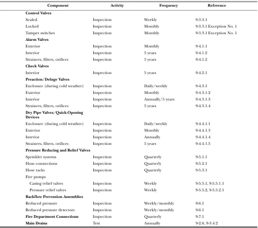
Table 2-1 Summary of Sprinkler System Inspection, Testing, and Maintenance
Item Activity Frequency Reference
Gauges (dry, preaction deluge systems) Inspection Weekly/monthly 2-2.4.2
Control valves Inspection Weekly/monthly Table 9-1
Alarm devices Inspection Quarterly 2-2.6
Gauges (wet pipe systems) Inspection Monthly 2-2.4.1
Hydraulic nameplate Inspection Quarterly 2-2.7
Buildings Inspection Annually (prior to freezing
weather)
2-2.5
Hanger/seismic bracing Inspection Annually 2-2.3
Pipe and fittings Inspection Annually 2-2.2
Sprinklers Inspection Annually 2-2.1.1
Spare sprinklers Inspection Annually 2-2.1.3
Fire department connections Inspection Table 9-1
Valves (all types) Inspection Table 9-1
Alarm devices Test Quarterly 2-3.3
Main drain Test Quarterly Table 9-1
Antifreeze solution Test Annually 2-3.4
Gauges Test 5 years 2-3.2
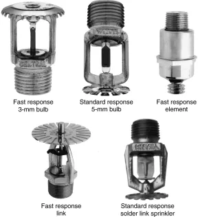
Sprinklers — extra-high temp. Test 5 years 2-3.1.1 Exception No. 3
Sprinklers — fast response Test At 20 years and every 10 years thereafter
2-3.1.1 Exception No. 2
Sprinklers Test At 50 years and every 10 years
thereafter
2-3.1.1
Valves (all types) Maintenance Annually or as needed Table 9-1
SPRINKLER SYSTEMS 25–17
2-3 Testing.
2-3.1 Sprinklers.
2-3.1.1* Where sprinklers have been in service for 50 years, they shall be replaced or representative samples from one or more sample areas shall be submitted to a recognized testing laboratory acceptable to the authority having jurisdiction for field service testing. Test procedures shall be repeated at 10-year intervals.
Exception No. 1: Sprinklers manufactured prior to 1920 shall be re-placed.
Exception No. 2: Sprinklers manufactured using fast response ele-ments that have been in service for 20 years shall be tested. They shall be retested at 10-year intervals.
Exception No. 3:* Representative samples of solder-type sprinklers with a temperature classification of extra high [325°F (163°C)] or greater that are exposed to semicontinuous to continuous maximum al-lowable ambient temperature conditions shall be tested at 5-year inter-vals.
Exception No. 4: Where sprinklers have been in service for 75 years, they shall be replaced or representative samples from one or more sample areas shall be submitted to a recognized testing laboratory acceptable to the authority having jurisdiction for field service testing. Test proce-dures shall be repeated at 5-year intervals.
2-3.1.2 A representative sample of sprinklers shall consist of a minimum of not less than 4 sprinklers or 1 percent of the number of sprinklers per individual sprinkler sample, which-ever is greater.
2-3.1.3 Where one sprinkler within a representative sample fails to meet the test requirement, all sprinklers represented by that sample shall be replaced. (See 2-4.1.1.)
Exception: Manufacturers shall be permitted to make modifications to their own sprinklers in the field with listed devices that restore the original performance as intended by the listing, where acceptable to the authority having jurisdiction.
2-3.2* Gauges. Gauges shall be replaced every 5 years or tested every 5 years by comparison with a calibrated gauge. Gauges not accurate to within 3 percent of the full scale shall be recalibrated or replaced.
2-3.3* Alarm Devices. Waterflow alarm devices including, but not limited to, mechanical water motor gongs, vane-type waterflow devices, and pressure switches that provide audible or visual signals shall be tested quarterly.
2-3.3.1* Testing the waterflow alarms on wet pipe systems shall be accomplished by opening the inspector’s test connection. Fire pumps shall not be turned off during testing unless all impairment procedures contained in Chapter 11 are followed.
Exception: Where freezing weather conditions or other circumstances prohibit use of the inspector’s test connection, the bypass connection shall be permitted to be used.
2-3.3.2* Testing the waterflow alarm on dry pipe, preaction, or deluge systems shall be accomplished by using the bypass connection.
2-3.4* Antifreeze Systems. The freezing point of solutions in antifreeze shall be tested annually by measuring the spec