PLUG FLOW REACTORS (PFR/ RAP)
Pertemuan 10REAKTOR ALIR PIPA (RAP), ATAU
PLUG FLOW REACTORS (PFR)
Pada bab ini dipelajari analisis unjuk kerja dan
perancangan RAP
Seperti RATB, RAP selalu dioperasikan secara
kontinyu pada keadaan tunak, selain daripada
periode startup dan shutdown
Tidak seperti RATB yg digunakan terutama untuk
reaksi2 fasa cair, RAP dapat digunakan untuk reaksi2
fasa cair dan fasa gas.
CIRI
CIRI
CIRI
CIRI----CIRI
CIRI
CIRI UTAMA
CIRI
UTAMA
UTAMA RAP
UTAMA
RAP
RAP
RAP
1. 1.1.
1. Pola aliran adalah PF, dan RAP adalah vesel tertutupPola aliran adalah PF, dan RAP adalah vesel tertutupPola aliran adalah PF, dan RAP adalah vesel tertutupPola aliran adalah PF, dan RAP adalah vesel tertutup
2. 2.2.
2. Kecepatan aliran volumetris dapat bervariasi secara Kecepatan aliran volumetris dapat bervariasi secara Kecepatan aliran volumetris dapat bervariasi secara Kecepatan aliran volumetris dapat bervariasi secara kontinyu kearah aliran sebab perubahan densitas kontinyu kearah aliran sebab perubahan densitas kontinyu kearah aliran sebab perubahan densitas kontinyu kearah aliran sebab perubahan densitas
3. 3.3.
3. Setiap elemen fluida mrp sistem tertutup (dibandingkan Setiap elemen fluida mrp sistem tertutup (dibandingkan Setiap elemen fluida mrp sistem tertutup (dibandingkan Setiap elemen fluida mrp sistem tertutup (dibandingkan
RATB); yaitu, tidak ada pencampuran kearah axial, RATB); yaitu, tidak ada pencampuran kearah axial, RATB); yaitu, tidak ada pencampuran kearah axial, RATB); yaitu, tidak ada pencampuran kearah axial, meskipun terjadi pencampuran sempurna searah radial meskipun terjadi pencampuran sempurna searah radial meskipun terjadi pencampuran sempurna searah radial meskipun terjadi pencampuran sempurna searah radial (dalam vesel silinder)
(dalam vesel silinder) (dalam vesel silinder) (dalam vesel silinder)
4. 4.4.
4. Sebagai konsequensi dari (3) sifat2 fluida dapat berubah Sebagai konsequensi dari (3) sifat2 fluida dapat berubah Sebagai konsequensi dari (3) sifat2 fluida dapat berubah Sebagai konsequensi dari (3) sifat2 fluida dapat berubah secara kontinyu kearah axial, tapi konstan secara radial secara kontinyu kearah axial, tapi konstan secara radial secara kontinyu kearah axial, tapi konstan secara radial secara kontinyu kearah axial, tapi konstan secara radial (pada posisi axial tertentu)
(pada posisi axial tertentu) (pada posisi axial tertentu) (pada posisi axial tertentu)
5. 5.5.
5. Setiap elemen fluida mempunyai residence time yg sama Setiap elemen fluida mempunyai residence time yg sama Setiap elemen fluida mempunyai residence time yg sama Setiap elemen fluida mempunyai residence time yg sama
seperti yg lain (dibandingkan RATB) seperti yg lain (dibandingkan RATB) seperti yg lain (dibandingkan RATB) seperti yg lain (dibandingkan RATB)
KEGUNAAN
KEGUNAAN
KEGUNAAN
KEGUNAAN RAP
RAP
RAP
RAP
Model RAP seringkali digunakan untuk sebuah reaktor yg mana sistem reaksi (gas atau cair) mengalir pada kecepatan relatif tinggi (Re>>, sampai mendekati PF) melalui suatu vesel kosong atau vesel yg berisi katalis padat yg di packed
Disini tidak ada peralatan seperti pengaduk, untuk menghasilkan backmixing
Reaktor dapat digunakan dalam operasi skala besar untuk produksi komersial, atau di laboratorium atau operasi skala pilot untuk mendapatkan data perancangan
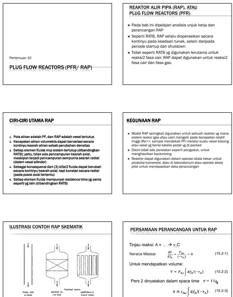
ILUSTRASI CONTOH RAP SKEMATIK
PERSAMAAN PERANCANGAN UNTUK RAP
Neraca Massa:
Tinjau reaksi: A + …
ν
cC
Untuk mendapatkan volume:
(15.2-1)
Pers 2 dinyatakan dalam space time
0(15.2-2)
KARENA
Bila pers (1) dituliskan kembali dalam gradien
f
Aterhadap perubahan posisi x dalam RAP
Asumsi reaktor berbentuk silinder dg jari-jari R.
Volume reaktor dari pemasukan sampai posisi x
adalah:
Substitusi dV ke pers (1) diperoleh
(15.2-4)
Gambar: Interpretasi pers (2) atau (3) secara grafik
NERACA
NERACA
NERACA
NERACA ENERGI
ENERGI
ENERGI
ENERGI
Pengembangan neraca energi untuk RAP, kita pertimbangkan hanya operasi keadaan tunak, jadi kecepatan akumulasi diabaikan.
Kecepatan entalpi masuk dan keluar oleh (1) aliran, (2) transfer panas, (3) reaksi mungkin dikembangkan atas dasar diferensial kontrol volume dV seperti gambar berikut:
1)
Kecepatan entalpi masuk oleh aliran –
kecepatan entalpi keluar oleh aliran
2)
Kecepatan transfer panas ke (atau dari)
kontrol volume
Dengan U adalah koef perpindahan panas
keseluruhan, T
Sadalah temperatur sekitar
diluar pipa pada titik tinjauan, dan dA adalah
perubahan luas bidang transfer panas
3)
Kecepatan entalpi masuk/ terbentuk (atau
keluar/ terserap) oleh reaksi
Jadi persamaan neraca energi keseluruhan (1),
(2), dan (3) menjadi:
Persamaan (5) mungkin lebih sesuai
ditransformasi ke hubungan T dan
f
A, karena
(15.2-5)
(15.2-6)
dan
dengan D adalah diameter pipa atau vesel,
substitusi (6) ke (7):
Jika digunakan pers (1) dan –(8) untuk
mengeliminasi dV dan dAp dari pers (5),
didapatkan
(15.2-7)
(15.2-8)
Secara alternatif, pers (5) dapat ditransformasi
ke temperatur sebagai fungsi x (panjang
reaktor), gunakan pers (6) dan (7) untuk
eliminasi dAp dan dV
Untuk kondisi adiabatis pers (9) dan (10) dapat
disederhanakan dg menghapus term U (
δ
Q = 0)
(15.2-10)
NERACA
NERACA
NERACA
NERACA MOMENTUM;
MOMENTUM;
MOMENTUM; OPERASI
MOMENTUM;
OPERASI
OPERASI
OPERASI NONISOBARIK
NONISOBARIK
NONISOBARIK
NONISOBARIK
Sebagai Rule of Thumb, untuk fluida kompresibel, jika perbedaan tekanan antara pemasukan dan pengeluaran lebih besar dp 10 sampai 15%, perubahan tekanan seperti ini mempengaruhi konversi, dan harus dipertimbangkan jika merancang reaktor.
Dalam situasi ini, perubahan tekanan disepanjang reaktor harus ditentukan secara simultas dengan perubahan fA dan perubahan T
Dapat ditentukan dengan pers Fanning atau Darcy untuk aliran dalam pipa silinder dapat digunakan (Knudsen and Katz, 1958, p. 80)
(15.2-11)
DENGAN P ADL TEKANAN, X ADL POSISI AXIAL DLM REAKTOR, Ρ ADL DENSITAS FLUIDA, U ADL KECEPATAN LINIER, F ADL FAKTOR FRIKSI FANNING, D ADL DIAMETER REAKTOR, DAN Q ADL LAJU ALIR VOLUMETRIK; Ρ, U, DAN Q DAPAT BERVARIASI DENGAN POSISI
Nilai f dapat ditentukan melalui grafik utk pipa
smooth atau dari korelasi. Korelasi yg digunakan
untuk aliran turbulen dalam pipa smooth dan
untuk bilangan Re antara 3000 dan 3000.000
(15.2-12)
CONSTANT-DENSITY SYSTEM
Pertemuan 111. ISOTHERMAL OPERATION
1. ISOTHERMAL OPERATION
1. ISOTHERMAL OPERATION
1. ISOTHERMAL OPERATION
For a constant-density system, since
14.3-12
then
The residence time t and the space time
τ
are
equal.
and
15.2-13
15.2-14 15.2-15
THE ANALOGY FOLLOWS IF WE CONSIDER AN ELEMENT OF FLUID (OF ARBITRARY SIZE) FLOWING THROUGH A PFR AS A CLOSED SYSTEM, THAT IS, AS A BATCH OF FLUID. ELAPSED TIME (T) IN A BR IS EQUIVALENT TO RESIDENCE TIME (T) OR SPACE TIME (Τ) IN A PFR FOR A CONSTANT-DENSITY SYSTEM. FOR DV FROM EQUATION 15 AND FOR DFA FROM 13, WE OBTAIN, SINCE FAO= CAOQO,
we may similarly write equation 2 as
15.2-16
A GRAPHICAL INTERPRETATION OF THIS RESULT IS GIVEN IN
FIGURE 15.4.
EXAMPLE 15-2
A liquid-phase double-replacement reaction between
bromine cyanide (A) and methyl-amine takes place in
a PFR at 10°C and 101 kPa. The reaction is
first-order with respect to each reactant, with k
A= 2.22 L
mol
-1s
-1. If the residence or space time is 4 s, and the
inlet concentration of each reactant is 0.10 mol L
-1,
determine the concentration of bromine cyanide at
the outlet of the reactor.
SOLUTION
The reaction is:
Since this is a liquid-phase reaction, we assume
density is constant. Also, since the inlet
concentrations of A and B are equal, and their
stoichiometric coefficients are also equal, at all
points, c
A= c
B. Therefore, the rate law may be
written as
A
FROM EQUATIONS 16 AND (A),
which integrates to
On insertion of the numerical values given for k
A,
t, and c
AO, we obtain
c
A= 0.053 mol L
-1EXAMPLE 15-3
A gas-phase reaction between methane (A) and
sulfur (B) is conducted at 600°C and 101 kPa in a
PFR, to produce carbon disulfide and hydrogen
sulfide. The reaction is first-order with respect to
each reactant, with k
B= 12 m
3mole
-1h
-1(based
upon the disappearance of sulfur). The inlet molar
flow rates of methane and sulfur are 23.8 and 47.6
mol h
-1, respectively. Determine the volume (V)
required to achieve 18% conversion of methane,
and the resulting residence or space time.
SOLUTION
Reaction:
CH4 + 2 S2
CS2 + 2 H2S
Although this is a gas-phase reaction, since
there is no change in T, P, or total molar flow
rate, density is constant. Furthermore, since
the reactants are introduced in the
stoichiometric ratio, neither is limiting, and we
may work in terms of B (sulphur), since k, is
given, with fB( = fA) = 0.18. It also follows that
cA = cB/2 at all points. The rate law may then
be written as
From the material-balance equation 17 and (A),
(A)
Since F
Bo= c
BOq
O, and, for constant-density, c
B= c
B0(l - fB), equation (B) may be written as
(B)
(C)
To obtain q
0in equation (C), we assume
ideal-gas behavior; thus,
From equation (C),
From equation 14, we solve for T:
2. NON ISOTHERMAL OPERATION
2. NON ISOTHERMAL OPERATION
2. NON ISOTHERMAL OPERATION
2. NON ISOTHERMAL OPERATION
To characterize the performance of a PFR
subject to an axial gradient in temperature, the
material and energy balances must be solved
simultaneously.
This may require numerical integration using a
software package such as E-Z Solve. Example
15-4 illustrates the development of equations and the
resulting profile for f
A, with respect to position (x)
for a constant-density reaction.
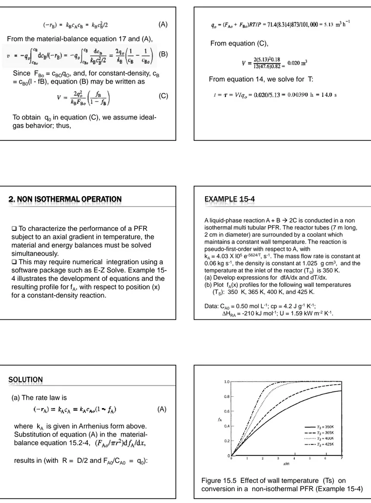
EXAMPLE 15-4
A liquid-phase reaction A + B 2C is conducted in a non isothermal multi tubular PFR. The reactor tubes (7 m long, 2 cm in diameter) are surrounded by a coolant which maintains a constant wall temperature. The reaction is pseudo-first-order with respect to A, with
kA= 4.03 X l05e-5624/T, s-1. The mass flow rate is constant at 0.06 kg s-1, the density is constant at 1.025 g cm3, and the temperature at the inlet of the reactor (T0) is 350 K. (a) Develop expressions for dfA/dx and dT/dx.
(b) Plot fA(x) profiles for the following wall temperatures (TS): 350 K, 365 K, 400 K, and 425 K.
Data: CA0= 0.50 mol L-1; cp = 4.2 J g-1K-1;
∆HRA= -210 kJ mol-1; U = 1.59 kW m-2K-1.
SOLUTION
(a) The rate law is
(A)
where k
Ais given in Arrhenius form above.
Substitution of equation (A) in the
material-balance equation 15.2-4,
results in (with R = D/2 and F
A0/C
A0= q
0):
Figure 15.5 Effect of wall temperature (Ts) on
conversion in a non-isothermal PFR (Example 15-4)
3. VARIABLE
3. VARIABLE
3. VARIABLE
3. VARIABLE----DENSITY SYSTEM
DENSITY SYSTEM
DENSITY SYSTEM
DENSITY SYSTEM
When the density of the reacting system is not
reacting system is not
reacting system is not
reacting system is not
constant through a PFR
constant through a PFR
constant through a PFR
constant through a PFR,,,,
The general forms of performance equations of
equations of
equations of
equations of
Section 15.2.1 must be used
Section 15.2.1 must be used
Section 15.2.1 must be used
Section 15.2.1 must be used.
The effects of continuously varying density are
usually significant only for a gas
significant only for a gas
significant only for a gas----phase reaction
significant only for a gas
phase reaction
phase reaction
phase reaction.
Change in density may result from any one, or a
combination, of: change in total moles (of gas
change in total moles (of gas
change in total moles (of gas
change in total moles (of gas
flowing), change in T , and change in P
flowing), change in T , and change in P
flowing), change in T , and change in P
flowing), change in T , and change in P .
We illustrate these effects by examples in the
following sections.
ISOTHERMAL, ISOBARIC OPERATION
Example 15.6
Consider the gas-phase decomposition of ethane (A)
to ethylene at 750°C and 101 kPa (assume both
constant) in a PFR. If the reaction is first-order with kA
= 0.534 s
-1(Froment and Bischoff, 1990, p. 351),
and
τ
is 1 s, calculate f
A. For comparison, repeat the
calculation on the assumption that density is
constant. (In both cases, assume the reaction is
irreversible.)
SOLUTION
The reaction is C2H6(A) C2H4(B) + H2(C). Since the rate law is
Stoichiometric table is used to relate q and q0. The resulting expression is
q = q
0(1+
f
A)
With this result, equation (A) becomes
(A)
(B)
THE INTEGRAL IN THIS EXPRESSION MAY BE EVALUATED ANALYTICALLY WITH THE SUBSTITUTION:
Solution of equation (C) leads to
(C)
fA = 0.361
If the change in density is ignored, integration of equation 15.2-17, with (-rA) = kACA = kACAo(1 - fA), leads to
from which
z = 1 -FA. The result is z = 1+ fA, the result is:
NONISOTHERMAL, ISOBARIC OPERATION
Example 15.7
A gas-phase reaction between butadiene (A) and ethene (B) is conducted in a PFR, producing cyclohexene (C). The feed contains equimolar amounts of each reactant at 525°C (T0) and a total pressure of 101 kPa. The enthalpy of reaction is - 115 k.I (mol A)-1, and the reaction is first-order with
respect to each reactant, with kA= 32,000 e-13,850/T m3
mol-1S-1. Assuming the process is adiabatic and isobaric,
determine the space time required for 25% conversion of butadiene.
Data: CPA= 150 J mol-1K-1; C
PB= 80 J mol-1K-1; Cpc = 250 J
mol-1K-1
SOLUTION
The reaction is C4H6(A) + C2H4(B) C6H10 (C). Since the molar ratio of A to B in the feed is 1: 1, and the ratio of the stoichiometric coefficients is also 1: 1, CA = CB throughout the reaction. Combining the material-balance equation (15.2-2) with the rate law, we obtain
Since kA depends on T, it remains inside the integral, and we must relate T to fA. Since the density (and hence q) changes during the reaction (because of changes in temperature and total moles), we relate q to fA and T with the aid of a stoichiometric table and the ideal-gas equation of state.
Since at any point in the reactor, q = FtRT/P, and the process is isobaric, 4 is related to the inlet flow rate q0by
That is,
Substitution of equation (B) into (A) to eliminate q results in
To relate fA and T, we require the energy balance (15.2-9) (C)
(D)
(E)
Substituting equation (E) in (D), and integrating on the assumption that (-∆HRA) is constant, we obtain
(F) (G)
RECYCLE OPERATION OF A PFR
RECYCLE OPERATION OF A PFR
RECYCLE OPERATION OF A PFR
RECYCLE OPERATION OF A PFR
In a chemical process, the use of recycle, that is, the
return of a portion of an outlet stream to an inlet to
join with fresh feed, may have the following purposes:
(1) to conserve feedstock when it is not completely
converted to desired products, and/or
(2) to improve the performance of a piece of
equipment such as a reactor.
CA
FAR
FAR (15.3-1)
where subscript R refers to recycle and subscript 1 to the vessel outlet. Equation 15.3-1 is applicable to both constant-density and variable-constant-density systems
M
R may vary from 0 (no recycle) to a very large value (virtually complete recycle).
Thus, as shown quantitatively below, we expect that a recycle PFR may vary in performance between that of a PFR with no recycle and that of a CSTR (complete recycle), depending on the value of R
Material balance for A around M: Constant-Density System
= (15.3-2)
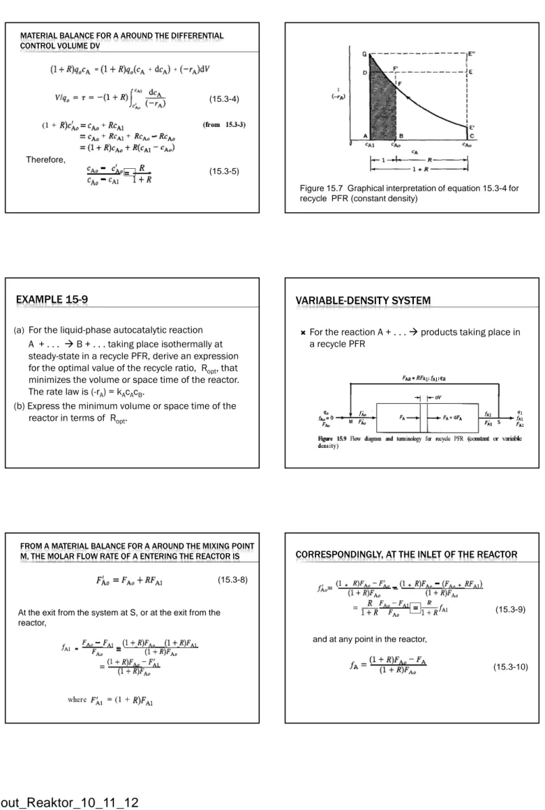
MATERIAL BALANCE FOR A AROUND THE DIFFERENTIAL CONTROL VOLUME DV
(15.3-4)
= (15.3-5)
Therefore,
Figure 15.7 Graphical interpretation of equation 15.3-4 for recycle PFR (constant density)
′′′′
EXAMPLE 15-9
(a)
For the liquid-phase autocatalytic reaction
A + . . .
B + . . . taking place isothermally at
steady-state in a recycle PFR, derive an expression
for the optimal value of the recycle ratio, R
opt, that
minimizes the volume or space time of the reactor.
The rate law is (-r
A) = k
Ac
Ac
B.
(b) Express the minimum volume or space time of the
reactor in terms of R
opt.
VARIABLE-DENSITY SYSTEM
For the reaction A + . . .
products taking place in
a recycle PFR
FROM A MATERIAL BALANCE FOR A AROUND THE MIXING POINT M, THE MOLAR FLOW RATE OF A ENTERING THE REACTOR IS
At the exit from the system at S, or at the exit from the reactor,
=
(15.3-8)
CORRESPONDINGLY, AT THE INLET OF THE REACTOR
= (15.3-9)
and at any point in the reactor,
EQUATING MOLAR FLOW INPUT AND OUTPUT, FOR
STEADY-STATE OPERATION, WE HAVE
from equation 15.3-10. Therefore,
(15.3-11)
That is, as R 0, V is that for a PFR without recycle; as R ∞, V is that for a CSTR