Hannes Gredler and Walter Goralski
The Complete IS-IS
Routing Protocol
Walter Goralski, Professor, Phoenix, AZ, USA
British Library Cataloguing in Publication Data
A catalogue record for this book is available from the British Library
Library of Congress Cataloging-in-Publication Data Gredler, Hannes.
The complete IS-IS routing protocol / Hannes Gredler, Walter Goralski. p. cm.
Includes bibliographical references and index. ISBN 1-85233-822-9 (pbk. : alk. paper)
1. IS-IS (Computer network protocol) 2. Routers (Computer networks) I. Goralski, Walter. II. Title
TK5105.5675.G74 2004
004.6′2--dc22 2004049147
Apart from any fair dealing for the purposes of research or private study, or criticism or review, as permitted under the Copyright, Designs and Patents Act 1988, this publication may only be reproduced, stored or trans-mitted, in any form or by any means, with the prior permission in writing of the publishers, or in the case of reprographic reproduction in accordance with the terms of licences issued by the Copyright Licensing Agency. Enquiries concerning reproduction outside those terms should be sent to the publishers.
ISBN 1-85233-822-9 Springer-Verlag London Berlin Heidelberg Springer Science+Business Media
springeronline.com
© Hannes Gredler 2005
The use of registered names, trademarks etc. in this publication does not imply, even in the absence of a specific statement, that such names are exempt from the relevant laws and regulations and therefore free for general use.
The publisher makes no representation, express or implied, with regard to the accuracy of the information con-tained in this book and cannot accept any legal responsibility or liability for any errors or omissions that may be made.
and an Adjunct Professor of Computer Science at Pace University Graduate School in New York. He has spent more than 30 years in the data communications field, including 14 years with AT&T, and is the author of several books on DSL, the Internet, TCP/IP and SONET, as well as of articles on data communications and other technology issues.
Hannes Gredleris a Professional Services Consultant at Juniper Networks Inc., where he is deploying/advising for numerous carriers and ISPs running the IS-IS, BGP and MPLS suite of protocols in their core backbones. He has been in the telecom industry for 7 years and holds a Master’s degree for Manufacturing and Automation from the Technical University of Graz (Austria). Hannes holds a CCIE certification (#2866) since 1997 as well as JNCIE (#22) certification since 2001. Besides his engagement at Juniper Networks, Inc., Hannes is actively involved in Open-Source Developments of networking decoders, where he contributed large parts of the Routing and Signaling Protocol Engines for tcpdump/libpcap http://www.tcpdump.org/ and Etherreal http://www.ethereal.com.
Foreword
IS-IS has always been my favourite Interior Gateway Protocol. Its elegant simplicity, its well-structured data formats, its flexibility and easy extensibility are all appealing – IS-IS epitomizes link-state routing. Whether for this reason or others, IS-IS is the IGP of choice in some of the world’s largest networks. Thus, if one is at all interested in routing, it is well worth the time and effort to learn IS-IS.
However, it is hazardous to call any routing protocol “simple”. Every design decision, be it in architecture, implementation or deployment, has consequences, some unantici-pated, some unknowable, some dire. Interactions between different implementations, the dynamic nature of routing, and new protocol features all contribute to making routing protocols complex to design, write and deploy effectively in networks. For example, IS-IS started as a link-state routing protocol for ISO networks. It has since evolved signifi-cantly: IS-IS has IPv4 and IPv6 (and IPX) addressing; IS-IS can carry information about multiple topologies; link attributes have expanded to include traffic engineering parame-ters; a new methodology for restarting IS-IS gracefully has been developed. IS-IS even has extensions for use in “non-packet networks”, such as SONET and optical networks, as part of the Generalized Multi-Protocol Label Switching (G-MPLS) protocol suite.
Understanding all of what IS-IS offers and keeping abreast of the newer protocol fea-tures is a weighty endeavour, but one that is absolutely essential for all serious network-ing engineers, whether they are developnetwork-ing code or runnnetwork-ing networks. For a long time, there were excellent books on OSPF, but very little on IS-IS. This encyclopaedic work changes that. Now, at last, there is a book that does IS-IS justice, explaining the theoret-ical aspects of IS-IS, practtheoret-ical real-life situations, and quirks in existing implementa-tions, and gives glimpses into some troubleshooting tools.
You couldn’t ask for a better-matched pair of guides, either. Hannes: intense, passionate, expert; and Walter: calm, clear, expert. Between the two, they have produced a compre-hensive, up-to-date text that can be used for in-depth protocol study, as a reference, or to catch up with the latest developments in IS-IS.
Happy reading!
Kireeti Kompella
Distinguished Engineer, Juniper Networks Inc. Common Control and Measurement Plane (ccamp) IETF Working Group Chair
Credits and Thanks
The authors would specifically thank the following individuals for their direct or indirect support for this book:
Walter
First of all, thanks to Hannes for giving me the opportunity to be involved in this project. What I know about IS-IS, I have learned from the Master. Patrick Ames made this book a reality, and Aviva Garrett provided inspired leadership. My wife Camille provided support, comfort, and the caring that all writers need.
Hannes
My biggest personal thank-you goes to my beloved wife Caroline. While she did so many good things for me, most importantly she created the environment for me that allowed me to write. Without her ongoing, loving support this book would never have been written up and finally published.
Patrick Ames has left a profound footprint on that book. While he had possibly the hardest job on earth (chasing part-time authors for manuscripts beyond due dates) he always kept calm, professional and provided care and input on all stages of this book. Without him this book would not have made its way.
Next I want to thank probably the best review team on IS-IS in the industry: first, the Juniper Engineering Team, most notably Dave Katz, Ina Minei, Nischal Sheth, Kireeti Kompella and Pedro Marquez who always took time and answered my questions in great detail. Tony Przygienda kept an eye from the IETF perspective on content accuracy and gave numerous suggestions to improve the text. The Service Provider Reviewing Team (Dirk Steinberg, Markus Schumburg, Ruediger Volk/Deutsche Telekom) and Nicolas Dubois (France Telekom) gave a lot of design inputs from the operational perspective.
Finally, I want to thank my Home Base, the Juniper Customer Service Europe Team: Jan Vos who initially helped in advocating writing a book and generously donated Company Lab and Team Resources; Anton Bernal for teaching me a lot about ATM; Josef Buchsteiner supported my work everyday by several useful discussions and help with lab setups. Finally, my team mate, Peter Lundqvist, for sharing a lot of his vast knowledge with me and being always good for a good laugh.
Contents
Foreword vii
Credits and Thanks ix
1 Introduction, Motivation and Historical Background 1
1.1 Motivation 1
1.2 Routing Protocols History in the 1990s 2
1.2.1 DECNET Phase V 2
1.2.2 NSFNet Phase I 3
1.2.3 OSPF 4
1.2.4 NLSP 5
1.2.5 Large-scale Deployments 6
1.2.6 IETF ISIS-WG 6
1.3 Sample Topology, Figures and Style 7
2 Router Architecture 11
2.1 Architecture and the Global Routing Paradigm 12
2.2 General Router Model 15
2.3 Routing and Forwarding Tables 17
2.3.1 Forwarding Plane Architectures 18
2.3.2 Control Plane Architectures 21
2.4 Router Technology Examples 26
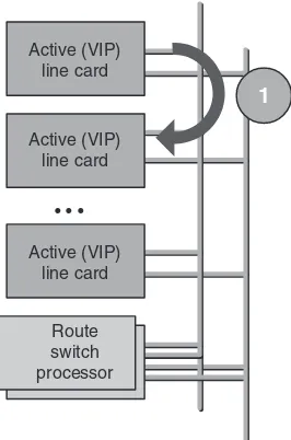
2.4.1 Cisco 7500 Series 27
2.4.2 Cisco 7500 Series⫹VIP Processors 29
2.4.3 Cisco GSR Series 30
2.4.4 Cisco IOS Routing Software 31
2.4.5 Juniper Networks M-Series Routers 31
2.4.6 JUNOS Routing Software 33
2.5 Conclusion 33
3 Introduction to the IOS and JUNOS Command Line Interface 35 3.1 Common Properties of Command Line Interfaces (CLI) 35
3.1.1 Operational Mode 36
3.1.2 Configuration Mode 39
3.1.3 Emacs Style Keyboard Sequences 40
3.1.4 Debugging 40
3.1.5 IP Troubleshooting Tools 41
3.1.6 Routing Policy 41
3.1.7 Logging 41
3.2 Cisco Systems IOS CLI 42
3.2.1 Logging into the System, Authentication, Privilege Level 42
3.2.2 IS-IS-related Show Commands 43
3.2.3 Interface Name-space 44
3.2.4 Changing Router Configuration 47
3.2.5 IS-IS-related Configuration Commands 50
3.2.6 Troubleshooting Tools 50
3.2.7 Routing Policy and Filtering of Routes 55
3.2.8 Further Documentation 56
3.3 Juniper Networks JUNOS CLI 56
3.3.1 Logging into the System and Authentication 57
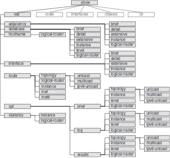
3.3.2 IS-IS-related Show Commands 59
3.3.3 Interface Name-space 60
3.3.4 IS-IS-related Configuration Commands 63
3.3.5 Changing the Configuration 65
3.3.6 Activating a Configuration 68
3.3.7 Troubleshooting Tools 69
3.3.8 Routing Policy 73
3.3.9 Further Documentation 77
3.4 Conclusion 77
4 IS-IS Basics 79
4.1 IS-IS and the OSI Reference Model 79
4.2 Areas 83
4.3 Levels 85
4.3.1 IS-IS Routing Hierarchy Rule 86
4.3.2 Route Leaking Between Levels 87
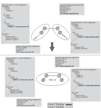
4.4 Area Migration Scenarios 90
4.4.1 Merging Areas 92
4.4.2 Splitting Areas 92
4.4.3 Renumbering Areas 92
4.5 Local SPF Computation 94
4.6 IS-IS Addressing 96
4.6.1 IP Addressing 96
4.6.2 IP Addressing Model 98
4.6.3 OSI Addressing 100
4.6.4 Examples of OSI Addressing 104
4.6.5 Configuring NETs 104
4.7 Names, System-, LAN- and LSP-IDs 105
5 Neighbour Discovery and Handshaking 109
5.1 Hello Message Encoding 109
5.1.1 LAN Hello Messages 111
5.1.2 Point-to-point Hello Messages 114
5.2 MTU Check 116
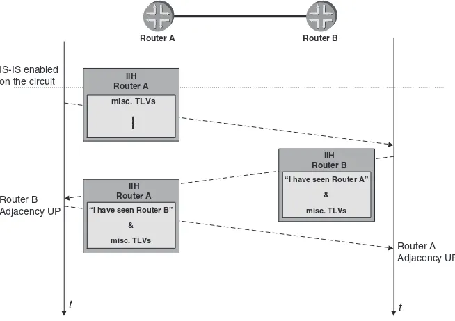
5.3 Handshaking 119
5.3.1 The 3-way Handshake on LAN Circuits 120
5.3.2 The 2-way Handshake on Point-to-point Circuits 123 5.3.3 The 3-way Handshake on Point-to-point Circuits 128
5.4 Sub-net Checking 131
5.5 Finite State Machine 133
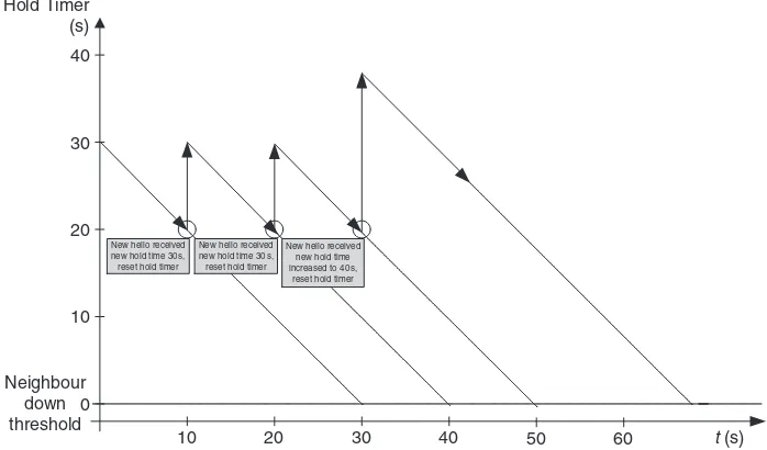
5.6 Neighbour Liveliness Detection 135
5.6.1 IGP Hellos 135
5.6.2 Interface Tracking 137
5.6.3 Bi-directional Fault Detection (BFD) 137
5.7 Summary 140
6 Generating, Flooding and Ageing LSPs 141
6.1 Distributed Databases 141
6.2 Local Computation 144
6.3 LSPs and Revision Control 146
6.3.1 Sequence Numbers 147
6.3.2 LSP Lifetimes 149
6.3.3 Periodic Refreshes 149
6.3.4 Link-state PDUs 152
6.4 Flooding 164
6.4.1 Is Flooding Harmful? 165
6.4.2 Mesh-Groups 168
6.5 Network-wide Purging of LSPs 172
6.5.1 DIS Election 173
6.5.2 Expiration of LSPs 174
6.5.3 Duplicate System-IDs 175
6.6 Flow Control and Throttling of LSPs 175
6.6.1 LSP-transmit-interval 176
6.6.2 LSP-generation-interval 178
6.6.3 Retransmission Interval 181
6.7 Conclusion 182
7 Pseudonodes and Designated Routers 183
7.1 Scaling Adjacencies on Large LANs 183
7.1.1 The Self-synchronization Problem 183
7.1.2 Scheduling Hellos 185
7.1.3 Applying Jitter to Timers 185
7.2 Pseudonodes 186
7.2.1 The N2Problem 186
7.2.2 Pseudonode Representation 188
7.2.3 Pseudonode ID Selection 191
7.2.4 Link-state Database Modelling 193
7.2.5 Pseudonode Suppression on p2p LANs 196
7.3 DIS and DIS Election Procedure 199
7.3.1 Pre-emption 200
7.3.2 Purging 201
7.3.3 DIS Redundancy 202
7.4 Summary 203
8 Synchronizing Databases 205
8.1 Why Synchronize Link-state Databases? 205
8.2 Synchronizing Databases on Broadcast LAN Circuits 208
8.3 Synchronizing Databases on p2p Links 216
8.4 Periodic Synchronization on p2p Circuits 218
8.5 Conclusion 222
9 Fragmentation 223
9.1 Fragmentation and the OSI Reference Model 223
9.2 The Too-small MTU Problem for IP 227
9.3 The Too-small MTU Problem for IS-IS 230
9.4 IS-IS Application Level Fragmentation 234
9.4.1 Hellos (IIHs) 234
9.4.2 Sequence Number Packets (SNPs) 236
9.4.3 Link-state Packets (LSPs) 240
9.5 Summary 245
10 SPF and Route Calculation 247
10.1 Route Calculation 247
10.2 The SPF Algorithm 248
10.2.1 Working Principle 248
10.2.2 Example 249
10.2.3 Pseudonode Processing 254
10.3 SPF Calculation Diversity 257
10.3.1 Full SPF Run 258
10.3.2 Partial SPF Run 267
10.3.3 Incremental SPF Run 270
10.4 Route Resolution 273
10.4.1 BGP Recursion and Route Dependency 273
10.4.2 BGP Route Selection 274
10.5 Prefix Insertion 276
10.5.1 Flat Forwarding Table 276
10.5.2 Hierarchical Forwarding Table 278
11 TLVs and Sub-TLVs 281
11.1 Taxonomy for Extensibility 281
11.1.1 Current Software Maturation Models 281
11.1.2 Ramifications of Non-extensible Routing Protocols 283 11.1.3 What Does it Mean When a Routing Protocol Is
Called Extensible? 284
11.2 Analysis of OSPF Extensibility 285
11.3 Analysis of IS-IS Extensibility 289
11.3.1 TLV Format 289
11.3.2 TLV Encoding 291
11.3.3 Sub-TLVs 293
11.3.4 TLV Sanity Checking 295
11.4 Conclusion 299
12 IP Reachability Information 301
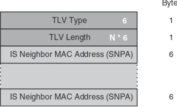
12.1 Old-style Topology (IS-Reach) Information 301
12.2 Old-style IP Reach (RFC 1195) Information 304
12.2.1 Internal IP Reachability TLV #128 304
12.2.2 Protocols Supported TLV #129 307
12.2.3 External IP Reachability TLV #130 309
12.2.4 Inter-Domain Information Type TLV #131 313
12.2.5 Interface Address TLV #132 314
12.2.6 IP Authentication TLV #133 317
12.3 New-style Topology (IS-Reach) Information 318
12.3.1 Automatic Metric Calculation 319
12.3.2 Static Metric Setting 320
12.4 New-style Topology (IP-Reach) Information 324
12.5 Old-, New-style Interworking Issues 327
12.6 Domain-wide Prefix Distribution 329
12.6.1 Leaking Level-2 Prefixes into Level 1 331
12.6.2 Leaking Level-1 External Prefixes into Level 2 337
12.6.3 Use of Admin Tags for Leaking Prefixes 339
12.7 Conclusion 344
13 IS-IS Extensions 345
13.1 Dynamic Hostnames 345
13.2 Authenticating Routing Information 351
13.2.1 Simple Text Authentication 351
13.2.2 HMAC-MD5 Authentication 353
13.2.3 Weaknesses 353
13.2.4 Point-to-Point Interfaces 355
13.2.5 Migration Strategy 356
13.2.6 Running Authentication Using IOS 358
13.2.7 Running Authentication Using JUNOS 361
13.2.8 Interoperability 364
13.3 Checksums for Non-LSP PDUs 367
13.3.1 PDUs Missing Checksum? 368
13.4 Ipv6 Extensions 370
13.4.1 IOS Configuration 373
13.4.2 JUNOS Configuration 374
13.4.3 Deployment Scenarios 376
13.5 Multi Topology Extensions 379
13.5.1 JUNOS Configuration 383
13.5.2 IOS Configuration 386
13.5.3 Summary and Conclusion 387
13.6 Graceful Restart 388
13.7 Summary 391
14 Traffic Engineering and MPLS 393
14.1 Traffic Engineering by IGP Metric Tweaking 393
14.2 Traffic Engineering by Layer-2 Overlay Networks 395
14.3 Traffic Engineering by MPLS 402
14.3.1 Introduction to MPLS 402
14.4 MPLS Signalling Protocols 408
14.4.1 RSVP-TE 408
14.4.2 Simple Traffic Engineering with RSVP-TE 409
14.4.3 LDP 417
14.4.4 Conclusion 422
14.5 Complex Traffic Engineering by CSPF Computations 422
14.6 LDP over RSVP-TE Tunnelling 428
14.7 Forwarding Adjacencies 433
14.8 Diffserv Aware Traffic Engineering 435
14.9 Changed IS-IS Flooding Dynamics 436
14.10 Conclusion 437
15 Troubleshooting 439
15.1 Methodology 439
15.2 Tools 441
15.2.1 Show Commands 442
15.2.2 Debug Logs 449
15.2.3 Configuration File 452
15.2.4 Network Analyzers 455
15.3 Case Studies 460
15.3.1 Broken IS-IS Adjacency 460
15.3.2 Injecting Full Internet Routes into IS-IS 469
15.4 Summary 474
16 Network Design 475
16.1 Topology and Reachability Information 475
16.2.1 Flooding 479
16.2.2 SPF Stress 480
16.2.3 Forwarding State Change Stress 481
16.2.4 CPU and Memory Usage 483
16.3 Design Recommendations 484
16.3.1 Separate Topology and IP Reachability Data 484 16.3.2 Keep the Number of Active BGP Routes per Node Low 485
16.3.3 Avoid LSP Fragmentation 485
16.3.4 Reduce Background Noise 488
16.3.5 Rely on the Link-layer for Fault Detection 489 16.3.6 Simple Loopback IP Address to System-ID Conversion
Schemes 490
16.3.7 Align Throttling Timers Based on Global Network Delay 492 16.3.8 Single Level Where You Can – Multi-level Where You Must 493
16.3.9 Do Not Rely on Default Routes 497
16.3.10 Use Wide-metrics Only 498
16.3.11 Make Use of the Overload Bit 499
16.3.12 Turn on HMAC-MD5 Authentication 499
16.3.13 Turn on Graceful Restart/Non-stop Forwarding 501
16.4 Conclusion 501
17 Future of IS-IS 503
17.1 Who Should Evolve IS-IS? 503
17.2 G-MPLS 504
17.2.1 Problems in the Optical Network Today 505
17.2.2 Cost of Transport 506
17.2.3 Overlay (UNI) G-MPLS Model 506
17.2.4 Peer G-MPLS Model 509
17.2.5 IS-IS G-MPLS Extensions 513
17.2.6 G-MPLS Summary 514
17.3 Multi-level (8-level) IS-IS 515
17.4 Extended Fragments 518
17.5 iBGP Peer Auto-discovery 520
17.6 Capability Announcement 523
17.7 Conclusion 524
Index 527
The Intermediate System to Intermediate System (IS-IS) routing protocol is the de facto standard for large service provider network backbones. IS-IS is one of the few remnants of the Open System Interconnect (OSI) Reference Model that have made their way into mainstream routing. How IS-IS got there makes a colourful story, a story that was deter-mined by a handful of routing protocol engineers. So in this very first chapter, it makes sense to explore the need for a book about IS-IS, cover some recent routing protocol history and give an overview about various IS-IS development stages. Finally, the chapter intro-duces a sample network and explains the style used in the figures throughout the book.
1.1 Motivation
One of the oddities of IS-IS is that there are hardly any materials available covering the
entireprotocol and how IS-IS is used for routing Internet Protocol (IP) packets. The base specification of the protocol was first published as ISO 10589 in 1987 and did not apply to IP packets at all. From then on, however, most of the work on the protocol has been done in the IS-IS working group of the Internet Engineering Task Force (IETF). The IETF was responsible for two major changes to the OSI vision of IS-IS. First, they extended the protocol by defining additional Type-Length-Values (TLVs) carrying new functionality. But then the IETF went much further and clarified many operational aspects of IS-IS. For example, adjacency management had not been exactly defined in RFC 1195, the first request for comment (RFC) to relate IS-IS to an IP environment. The lack of details caused implementers to code behaviours differently from what the basic specification required the protocol to do. As a result, there is a lot of good IS-IS literature available that covers the base IS-IS protocol and its extensions, but not the implementa-tion details. However, discussing IS-IS purely on a theoretical basis is not enough. Throughout this chapter, you will find that a lot of the reasons why things are the way they are in IS-IS is dependent on implementation choices (often caused by router operating system (OS) constraints), not the fundamentals of the IS-IS specification. And that is the whole reason for this book.
Real-world IS-IS implementations are the main focus of this book. The two vendors shipping all but a tiny fraction of the IS-IS code used for IP routing on the Internet are Cisco Systems, Inc. and Juniper Networks, Inc. The routing OS suite of Juniper Networks
1
Introduction, Motivation and
Historical Background
Inc. (JUNOS Internet software) and Cisco Systems (IOS) are subjected to close examination throughout this book. We will compare implementation details, and compare the overall implementation against the specification. Furthermore, both IOS and JUNOS carry scal-ability improvements for IS-IS, which will be highlighted as well.
The purpose of this book is to provide a good start for the self-education of both the novice and the seasoned network engineer in the IS-IS routing protocol. The consistent approach is to explain the theory and then show how things are implemented in major vendor routing OSs. That way, we hope to close the gap between barely specified speci-fication and undocumented vendor-specific behaviour.
1.2 Routing Protocols History in the 1990s
IS-IS started off as a research project of Digital Equipment Corporation (DEC) in 1986. Radia Perlman, Mike Shand and Dave Oran had worked on a successor network archi-tecture for Digital’s proprietary minicomputer system family. The suite of protocols was named DECNET. By the time the product became DECNET phase IV, it was obvious that the architecture lacked support for large address spaces and displayed slow conver-gence times after re-routing events like link failures. Clearly, a new approach to these problems, which occurred in all networks and with all routing protocols at the time, was desperately needed.
1.2.1
DECNET Phase V
The new architecture called DECNET Phase V was based on an entirely new routing tech-nology called link-staterouting. All previous packet-based network technology at that time was based on variations of distance-vector routing (sometimes also referred to as Bellman-Ford routing) or the Spanning Tree Algorithm. The idea of routers disseminat-ing and maintaindisseminat-ing a topological database on which they all performed a Dijkstra (Shortest Path First, or SPF) calculation was a revolutionary approach to networking. This database processing demanded a certain amount of sophistication in router CPUs (central process-ing units) and not all routers had what it took. However, all of the urban legends revolv-ing around the “CPU-intensive” and cycle-wastrevolv-ing properties of link-state algorithms mostly had their origin in subjective opinions about router power at that time. Certainly no modern router needs to worry about the CPU cycles needed for link-state algorithms. The most interesting property about DECNET Phase V was that it was – and is – a very extensible protocol. It runs directly on top of the OSI Data Link Layer protocol. That makes the protocol inherently independent of any higher Network Layer Reach-ability Protocol. In 1987, the International Organization for Standardization (usually abbre-viated as ISO) adopted the protocols used in DECNET Phase V as the basis for the OSI protocol suite. A whole array of networking protocols was standardized at the time. A brief list of the adopted protocols would include:
•
Transport Layer (TP2, TP4)•
Network Layer Reachability (CLNP)•
Router to Host (ES-IS)•
Router to Router, Interdomain (IDRP)•
Router to Router, Intradomain (IS-IS)Finally, the Intermediate to Intermediate System Intradomain Routing Exchange Protocol(to give IS-IS its official name) was published as ISO specification ISO 10589. First-time readers tend to get confused by the sometimes arcane “ISO-speak” used in the document. IS-IS itself, in contrast to its specification, is actually a fine, lean protocol. After learning which sections of ISO 10589 to avoid, readers find that IS-IS is a simple protocol with almost none of the complicated state transitions that make other interior gateway protocols (IGPs) so difficult to operate properly under heavy traffic loads today. Besides the ISO jargon in the specification, readers often get caught up in and confused by the distinc-tions between the routing protocol definidistinc-tions (IS-IS itself) and the higher-level network reachability definitions (known as the connectionless network protocol, or CLNP) and this makes differentiating IS-IS and CLNP more difficult. Henk Smit, a well-respected imple-menter of the IS-IS protocol, once with Cisco Systems, noted on the NANOG Mailing List:
IS-IS is defined in ISO document 10589. It defines the base structures of the protocol (adjacencies, flooding, etc). Unfortunately it also defines lots of CLNP specific TLVs. So it looks like IS-IS is a routing protocol for CLNP, and the IP thing is an add-on. That is partly true, but the ability to carry routing info for any layer 3 protocol is a well designed feature. I suspect IS-IS might be easier to understand if the CLNP specific part was separated from the base protocol.
So IS-IS can be used for routing IP packets just as well as the other major link-state protocol, the Open Shortest Path First (OSPF) protocol. But why bother having another link-state IGP for routing TCP/IP, especially if it is so similar to OSPF? At first sight, supporting both OSPF and IS-IS seems to be a double effort. Only by looking back can it be easily understood why IS-IS has its place in today’s Internet.
1.2.2
NSFNet Phase I
In 1988, the NSFNet backbone of the Internet was commissioned and deployed. The NSFNet was the first nationwide network that routed TCP/IP traffic. The IGP of choice for the NSFNet was a lightweight knockoff version of IS-IS, which was later documented in RFC 1074 as “The NSFNET Backbone SPF based Interior Gateway Protocol”. The implementer and author of the document is now a famous name in the history of inter-networking: Dr Yakov Rekhter, at this time working at IBM on networking protocols at the Thomas Watson Research Center. The main differences between the IS-IS as defined in ISO 10589 and that used on the NSFNet were encapsulation, addressing, media sup-port and the number of IS-IS levels. The NSFNET backbone IGP ran on top of IP rather than directly on top of the OSI Link Layer, and IP Protocol Type 85 was used as a trans-porting envelope. ISO 10589 only specified a CLNP-related address space called the Network Service Access Point (NSAP). Rather than defining an extra TLV that carried IPv4 addresses and administrative domain information, both types of information are folded into a 9-byte NSAP string which is illustrated in Figure 1.1.
(DRs) and what IS-IS called “pseudonode” origination. Pseudonode origination and LAN “circuits” will be covered in greater detail in Chapter 7, “Pseudonodes and Designated Routers”. At that time, this change was perceived as no big deal as the NSFNet was a pure WAN network consisting of a bunch of T1 (1.544 Mbps) lines.
The NSFNet link-state routing protocol gave NSFNet its first experience with the sometimes catastrophic dynamics of link-state protocols and resulted in network-wide meltdowns. We will cover the robustness issues and the lessons learned from the infancy of link-state routing protocols in Chapter 6, “Generating Flooding and Ageing LSPs”. But early bad experiences ultimately provided a good education for the early imple-menters, and their knowledge of “how notto do things” helped to create better imple-mentations the second time around.
1.2.3
OSPF
In 1988, the IETF began work on a replacement for the Routing Information Protocol (RIP), which was proving insufficient for large networks due to its “hop count” metric limitations. Also, the limited nature of the Bellman-Ford algorithm with regard to con-vergence time provided serious headaches in the larger networks at that time. It was clear that any replacement for RIP had to be based on link-state routing, just like IS-IS. The Open Shortest Path First Working Group was born. The OSPF-WG group closely watched the IS-IS developments and both standardization bodies, the IETF and ISO, effectively copied ideas from each other. This was no major surprise, as mostly the same individuals were working on both protocols.
The first implementation of OSPF Version 1 was shipped by router vendor Proteon. A short while later, both DECNET Phase V (which was effectively IS-IS) and OSPF were being deployed. Controversy and dispute raged within the IETF concerning whether to adopt IS-IS or OSPF as the officially endorsed IGP of the Internet. At that time, there was much fear expressed by some influential individuals about the perceived “OSI-fication” of the Internet. Those fears were fed by the belief on the part of the OSI camp that IPv4 was just a temporary, “non-standard” phenomenon that ultimately would go away, replaced by firm international standards like CLNP, CMIP and TP2, TP4. Most discussions about what was the best protocol were based on emotions rather than facts. At one IETF meeting there was bickering and shouting, and even a T-shirt distributed displaying the equation:
IS-IS⫽0
4 1. Introduction, Motivation and Historical Background
Administrative Domain
Bytes
2
2
4 Reserved
IPv4 Address
Reserved 4
It is hard to believe today that there were ever any serious doubts about the future of IP. But things did not change until 1992. With the rise of the World Wide Web as the “killer application” for the new, global, public Internet, it was evident that the Network Layer protocol of choice was to be the Internet Protocol (IP) and not CNLP. The projected demise of CNLP nurtured the belief that the entire OSI suite of protocols would disappear soon.
The IETF reckoned that there should be native IP support for IS-IS and formed the IS-IS for IP Internets working group. In 1990, IS-IS had become “IP-aware” with the pub-lication of RFC 1195, authored by Ross Callon, a distinguished protocol engineer now with Juniper Networks. RFC 1195 describes a set of IP TLVs forIntegrated IS-IS which can transport both CLNP and IP routes. These early IP TLVs and their current successors are discussed in greater detail in Chapter 12, “IP Reachability Information” and Chapter 13, “IS-IS Extensions”.
The IETF continued both IGP working groups (OSPF-WG, ISIS-WG) and wisely left the decision which protocol to adapt to the marketplace. The IETF declared both proto-cols as equal, which proved in fact not to be really true, since there was some soft, but per-sistent, pressure to give OSPF preference for Internet applications. Hence people often say, “IS-IS and OSPF are equal, but OSPF is more equal.” Ultimately, Cisco Systems started to ship routers with support for both OSPF and CLNP-only IS-IS (useless for IP), but commenced work on Integrated IS-IS, which could be used with IP.
1.2.4
NLSP
In the 1980s, LAN software vendor Novell gained popularity and finally emerged as the pri-mary vendor of PC-based server software. The Novell Packet Architecture was composed of both a Network Layer protocol they called the Internet Packet Exchange (IPX) protocol and a routing protocol to properly route packets between sub-nets. Novell’s first generation rout-ing protocol was based on RIP and used distance vector technology. Novell then decided to augment their network architecture with link-state routing. At that time, DEC was widely known for their link-state routing experience, and so Novell recruited Neil Castagnoli, who was one of the key scientists at DEC responsible for DECNET Phase V.
One of the prime goals of IS-IS from the very start was independence from Network Layer routing protocols. In other words, IS-IS just distributed route information, and did not particularly care which protocol was actually used to transport traffic. Novell came up with NLSP, which was effectively an IS-IS clone. Many of the original IS-IS mechan-isms and protocol data unit (PDU) types were retained. For IPX-specific routing infor-mation and Novell-specific service location protocols (used to find which stations on the LANs were servers) the TLVs from 190 to 196 have been allocated for Novell-specific routing needs. Although NLSP looks largely the same as IS-IS, some of the mechanisms, particularly the “stickiness” of the DR election process, make NLSP incompatible with regular IS-IS routers.
Responding to increasing demand from customers, Cisco Systems began shipping NLSP in 1994. Because NLSP and IS-IS are so similar, Cisco’s engineering department decided to do some internal code housekeeping and merged the base functions of the two protocols in one “tree”. This rewriting work was the springboard for one of the most respected IGP routing protocol engineers in the world. Cisco Systems hired a software engineer named Dave Katz from Merit, the management company of the NSFNet backbone. Merit was, in the early 1990s, the place where many of the huge talents in Internet history got their routing expertise.
1.2.5
Large-scale Deployments
Cisco gained a lot of momentum in the early 1990. The company attracted all the key talent in routing protocol and IP expertise and finally got more than a 98 per cent market share in the service provider equipment space. When the first big router orders were placed and the routers deployed for the Web explosion, Internet service provider (ISP) customers started to ask their first questions about scalability. Service providers were interested in a solid, quickly converging protocol that could scale to a large topology containing hundreds or even thousands of routers. Cisco’s proprietary, distance-vector EIGRP was not really a choice because the convergence times and stability problems of distance-vector-based protocols were well known from word-to-mouth in the service provider community. Ironically, it was Cisco’s recent code rewrite that made IS-IS more stable than the implementations of OSPF available at the time. For a while, IS-IS was believed to be as dead as the OSI protocols. However, the 1980s mandate of the US gov-ernment for supporting OSI protocols under the Govgov-ernment OSI Profile (GOSIP) speci-fication (which was still in effect), plus recently gained stability, made IS-IS the logical choice for any service provider that needed an IGP for a large number of nodes.
From about 1995 to 1998 the popularity of IS-IS within the ISP niche continued to grow, and some service providers switched from OSPF. Even in large link-state areas, IS-IS proved to be a stable protocol. At the beginning of 1998, the European service providers switched from their trying EIGRP and OSPF experiences to IS-IS, most notably because of the better experiences that the US providers had with IS-IS. That trend continues today. All major European networks are running routing protocols based on IS-IS.
1.2.6
IETF ISIS-WG
From 1999, most of the IS-IS extensions for IP are done within the IETF and not within ITU-T or ISO committees. Most of the basic IS-IS protocol is maintained in ITU-T, but little of it has changed in the past decade. The IS-IS working group inside the IETF (http://www.ietf.org/html.charters/isis-charter.html) maintains the further development of IS-IS. Most IETF work is typically carried out in the form of mailing lists. There are further details about this split of responsibilities and the resulting issues in Chapter 17, “Future of IS-IS”.
There is a small group of individuals from vendors and ISPs interested in the further development of IS-IS. Because the community is so small, consensus is reached very fast
and the standardization process itself is often just a matter of documenting the existing behaviour that has already been deployed in the field.
All the most recent enhancements to IS-IS have initially been published as Internet drafts. At the end of the year, all the major extensions are either republished as an RFC or are placed in the RFC editors’queue for release. Activity on the IETF mailing list is nowa-days moderate to low, as all of the most pressing problems and extension behaviours have already been solved. Chapter 17 deals with the future of the protocol and highlights some of the not-yet deployed extensions, which concern service discovery and aids to network operations.
1.3 Sample Topology, Figures and Style
In an effort to make the individual chapters more concise and to be consistent, we have applied a common style and topology to illustrations. In order to put the different scen-arios that are explained throughout into perspective, we refer to a small service provider network as illustrated in Figure 1.2. We believe that a realistic reference topology is of
Area 49.0001
much more use than symbolic names like Router A or Router B, particularly when it comes to explaining complex procedures like flooding in a distributed environment.
The reader will also find a vast amount of debug, show command and tcpdump output containing IPv4 addresses. Figure 1.3 illustrates the IPv4 sub-net address allocation for the sample topology. Although the majority of display output has been taken from live routers on the Internet, we have changed the addressing to a common scheme. Although in a real network one would never deploy addressing based on non-routable RFC 1918 addresses, this is done throughout the book in order to protect the integrity of public, routable address spaces. The 172.16.33/24 address range has been allocated to link addressing and the 192.168.0/27 pool is allocated for router loopback addresses.
8 1. Introduction, Motivation and Historical Background
172.16.33.16/30
172.16.33.0/30
172.16.33.12/30
172.16.33.4/30
172.16.33.20/30 172.16.33.28/30
172.16.33.24/30 172.16.33.8/30
New York London
Pennsauken
Wash D.C.
Pennsauken
Frankfurt London
Washington New York
Paris
192.168.0.17
192.168.0.19 192.168.0.12
192.168.0.21 192.168.0.8
192.168.0.22
This book should also serve as a reference for people learning about the encoding style of the IS-IS protocol. Too often the authors found the entire TLV and sub-TLV structure difficult to understand. Figure 1.4 illustrates the shading style used to colour all protocol-related illustrations. The darker the background colour, the lower the field is located in the OSI protocol stack. So the dark gray shading indicates link-layer encapsulation such as Ethernet or PPP or C-HDLC. Then gray tones are used for the IS-IS common header, IS-IS PDU specific headers, the TLVs and its sub-TLVs.
Layer-2 Header
IS-IS common header
TLV PDU
subTLV
2
Router Architecture
11
Every networking professional knows the situation. You’re at a party with relatives where people always seem to know somehow that you deal with the Internet (probably those relatives). If you have bad luck, at some stage the conversation at the table is about the Internet and how it might work. The trickiest task is then to explain to Grandma in five minutes how the Internet works. Not that Grandma bothers to try and understand. In fact, she still thinks that all those cables that disappear into the wall go all the way under the Atlantic and that’s the way that it works.
But the truth is, explaining how the Internet works is surprisingly easy: the Internet consists of a vast collection of hosts and routers. Routers are the “glue” that holds these hosts together. The routers form a meshed network, very much like the road system where the routers can be compared to interchanges or junctions and the fibre optic cables in between the routers are the highways. The host computers are like houses placed on smaller roads (these side roads are smaller networks or sub-nets), each having a unique address.
Surprisingly, Internet hosts and routers are almost completely isolated from each other. Hosts do not generally exchange any signalling information with routers. All that hosts need to know (normally by static configuration) is the address of the router on their local sub-net. Hosts can forward any non-local traffic for hosts on other networks to this
default routerordefault gateway. Almost everyone reading this book has probably con-figured this default on their local PC or workstation. In contrast to the hosts, which almost have no routing information at all besides the default route, the routers have all the routing information they need. However, the routers do not have any idea about the applications (such as a Web browser) or the transport protocols (such as TCP) that applications rely upon. It is the hosts that do indeed have to know about the state of the transport protocol and how applications access the network. This is the first instance where, for the sake of simplicity, a clever partitioningof the problem has occurred. This chapter presents more examples where you realize that there is more than one place in the overall Internet and router architecture where partitioningthe original problem has helped to resolve the issue. Partitioning is the architectural tool that helps scale the IP universe further than at first appears possible.
illustration, common routing platforms from both Cisco Systems and Juniper Networks will be discussed at the end of the chapter.
2.1 Architecture and the Global Routing Paradigm
The current routing and forwarding architecture follows a datagram-based, End-System (host) controlled, unidirectional, destination-oriented, hop-by-hop routing paradigm. Don’t worry, all of these technical terms are explained piece-by-piece below.
1. Datagram-based:Routers only think in terms of datagrams, which are packets that flow independently from host to host without regard for sequence or content integrity. In this respect routers are unlike End Systems which haveto track the state of con-nections, perform all kind of transport protocol (TCP) functions like making sure arriving packets are in sequence, asking for resends of missing packets, and so on. A router is completely oblivious to the sessionsthat it has to transport between hosts. Early routers had knobs (small, on/off configuration tags like “disable/enable”) for packet lookup, filtering and accounting on a per-flow (session) basis. However, the impact of introducing a session or flow orientation to core routers and the resulting load of the system was just too big. Today, flow orientation, which demands session awareness in every router, and high-speed circuits are mutually exclusive. Flow orien-tation is only enabled on low-bandwidth circuits (2 Mbps or less), due to its high CPU impact. Core routers today are completely unaware of any sessions or flows. This
statelessbehaviour means that a route lookup for a packet at time N⫹1 is totally independent of the packet lookup at time N. The router just tries to deliver the packet as fast as it can. If a packet cannot be delivered because the outbound interface is con-gested, then the packet will be queued. If the queues (some call them buffers) are satu-rated then the packet will be silently discarded. Silent discard is a technique that does not send explicit congestion messages to the sender. Suppressing explicit congestion messages does not further harm the networks’ resources if the network is already satu-rated. Although core routers should not worry about individual flows they must not change reorder packets within a given flow. Typically, it is expected that the end systems receive packets in sequence. There might be situations, as in re-routing scenarios or badly implemented load-sharing mechanisms, where packets in a single flow are re-sequenced by the transit routers. The IP routing architecture completely offloads key functions like flow control, reliable transmission, and re-sequencing to the End Systems. This allows simpler router functions.
Transfer Protocol(SMTP) augments the stream with transport protocol level infor-mation like sequence numbers. The augmented transport stream next is passed down the network protocol stack to the IP layer where each message segment is prepended with an IP header. The packet then leaves the End System and is either sent directly to the receiving end system (if it is on the same network) or passed to the default router. Then the transport protocol just hopes that the message segment eventually arrives at the receiving end system. All the transport protocols can do on both sides isdetecta missing segment. By looking at the sequence numbers, the transport proto-col detects a missing segment and requests retransmission if desired (some forms of real-time traffic, like voice and video, do not have the luxury of this option). Even more sophisticated actions are performed by the transport protocols. For example, if the pace of the receiving segments is varying, typically an indication of congestion, the receiver can signal back to the sender to back off and reduce the transmit rate. The only way of communicating congestion from the routers to the End Systems is increased delay or packet loss, which is just a case of infinite delay.
3. Unidirectional:Some communication architectures like ATM or Frame Relay have the implicit assumption that the circuit going from End System A to End System B is utilized for the opposite direction. This means that traffic from End System B to End System A follows exactly the same path (a connection) through the network. In the IP routing world, this is not necessarily the case. Routing information, which are point-ers to traffic sources, are always unidirectional. For working communication a router needs to have tworoutes: one route pointing to the sender’s network and one route pointing to the receiver’s network. Popular networking troubleshooting tools like the ping program always check to see if there is bidirectional connectivity between a pair of hosts.
Architecture and the Global Routing Paradigm 13
TCP stream TCP stream
End systems
Unreliable datagram relaying service Application (SMTP)
Sequence numbers
IP datagram IP header
Routers Application (SMTP)
Sequence numbers
IP header
Sender Receiver
IP datagram
4. Destination-oriented:Each router along the transmission path between a pair of End Systems has to make a decision where to forward the packets. This decision could, hypothetically speaking, be based upon any field in the IP header, such as marked in Figure 2.2. All of the bright-gray fields like destination IP address, source IP address and precedence bits (also called the Type of Service (TOS) byte) could form the basis for a routing decision. But today on the Internet, only the destination IP address is used by routers for making forwarding decisions. Since the early 1990s there have been efforts to use the TOS byte for routing lookups as well; however, this routing paradigm has had no great success. Today the TOS (or Diffserv byte, as it is often called today) only helps to control the queuing schedule of packets inside a router, but cannot influence the forwarding decision. Both Cisco Systems and Juniper Networks offer features called policy routing or filter based forwarding, where the network operator can override the default destination-based routing scheme by specifying arbitrary fields in the IP header to influence the routing decision. But these features are typically deployed at the edge or access portions of the network. It is safe to say that the core of the Internet is purely destination-oriented.
5. Hop-by-hop routing: Communication architectures like ATM rely on a connection setup where the sender predetermines the route to the destination. Once a message is put on a previously established Switched Virtual Connection (SVC) the message will be relayed straight from the source to the destination without complex routing deci-sions in the intermediate systems (usually called switchesin such connection-oriented architectures). The whole transmission path is pre-computed by the source. The ATM forwarding paradigm thereby follows a source routingmodel. The IP routing archi-tecture is very different. Clearly there are common ideas, such as that the packet should use the shortest path from the source to the destination. But contrary to ATM switches, IP routers each compute independentlywhat the bestroute is from A to B. Obviously, this must follow a common scheme that each router follows, otherwise forwarding loops could result from conflicting path selection algorithms. The com-mon path selection algorithms are various forms of least-costrouting. Each routing protocol defines a set of metrics, and if there is more than one next hop with equal metrics, a tie-breaking scheme allows each router to determine the “best” route to a
Version Header
length TOS Total length
Identification Flags Fragment offset
Time to live Protocol Header checksum
Source address
Destination address
Bytes
4
4
4
4
4
given destination, but only from the viewpoint of the local router. This concerted, but still independent, computing of forwarding tables in routers is called hop-by-hoprouting.
Four of the above five points specify how routers should “think” in terms of forward-ing traffic. In 1985, when the first commercial routers shipped, peak processforward-ing of packets at 1000 packets per second (pps) were feasible. With the explosion of Internet traffic, routers today must offer sustainedpacket processing rates of hundreds of millions pps. What has changed? While the original forwarding paradigms are still in place, router hardware and architectures have constantly improved a router built in 2004 can forward at a factor of 10,000 more traffic than a router made in 1992.
2.2 General Router Model
In the Internet model, smaller networks are connected to bigger networks through routers. Originally routers were implemented on general purpose workstations (typically UNIX-based platforms; PCs running DOS or Windows were much too slow). These early routers had a single CPU, which had to do two things:
•
Routing•
ForwardingRouting means discovering the network topology and disseminating information about directly connected sub-nets to other neighbourrouters.Forwardingrefers to the look-up and transfer of packets to the matching outbound next-hop for a given packet. Routing, as defined here, mainly concerns signalling information and forwarding mainly concerns user information.
As long as the general purpose processor has infinite processing power and memory, the union of both routing and forwarding functions in the same device does no harm. Practically speaking, processing power and memory are always finite resources and experience has shown that the two functions mutually influence each other in their competition for processing and storage resources. Unifying routing and forwarding may cause stability problems during transient conditions, for instance, when a large traffic trunk needs to be rerouted. Typically, during these transient situations, both the routing subsystem of the box as well as the forwarding subsystems are extraordinarily stressed.
The stress occurs because the routing subsystem has to calculate alternative paths for the broken traffic trunk and, at the same time, the forwarding process may be hit by a large wave of traffic being rerouted through this router by another router. And that is exactly the problem with the unified design combining routing and forwarding. It only works as long as just onesubsystem is stressed, but not both.
For example, what happens when the central CPU is 100 per cent utilized? Not all traf-fic can be routed and packets have to be dropped. If the signalling or control traftraf-fic gen-erated by the routing protocols is part of the dropped traffic, this may result in further topology changes and result in endless stress (churn) that propagates through the whole network.
Such meltdowns have occurred in every major ISP network throughout the last decade, and the result was a radical design change in how routers are built. The forwarding
subsystem was separated from the general purpose platform, and migrated to custom hardware that can forward hundreds of millions of packets per second. Customized hard-ware development was necessary as the Internet growth outperformed any PC-based architecture based on, for example, PCI buses.
Figure 2.3 shows essentially how modern routers are structured. The router is parti-tioned into a dedicated control plane and a forwarding plane. The control plane holds the software that the router needs to interact with other routers and human operators. Routers typically employ a powerful command line interface (CLI), which is used for provision-ing services, configuration management, router troubleshootprovision-ing and debuggprovision-ing pur-poses. Operator actions are written down in a central configuration file.Changes of the configuration file are propagated to the routing processes that “speak” router-to-router protocols like OSPF or IS-IS or Border Gateway Protocol (BGP). If the same routing protocol is provisioned on both ends of a direct router-to-router link, then the routers start to discover each other in their network. Next, IP routing information is exchanged. Theremotenetwork information is entered in the localrouting table of the route processor. Next, the forwarding table entries in the control plane and the packet forwarding plane have to be synchronized. Based on this routing table, the forwarding plane starts to program the router hardware, which consists of Application Specific Integrated Circuits (ASICs) or Field Programmable Gate Arrays (FPGAs), with a subset of the rout-ing table, which is now called the forwarding table. The forwarding table is usually a concise version of the full routing table containing all IP networks. The forwarding table only needs to know routes useful for packet forwarding.
The fowarding plane consists of a number of “input interfaces” (IIF) and a number of “output interfaces” (OIF). The router itself thinks in terms of logicalinterfaces. The physical interface is the actual wire (or fibre) over which the packets flow. In order to actually use a physical interface for forwarding traffic, there needs to be at least one IP address assigned to the interface. The IP address combined with a physical interface is called a logical interface. There can be more than one logical interface per physical inter-face if the underlying physical media supports channel multiplexing like 801.1Q, Frame
Control plane
Forwarding plane
Routing
process(es) CLI
SNMP process
OS kernel
Transit traffic Transit traffic
Lookup Fabric Queuing
IIF OIF
FIGURE 2.3. A blueprint of a modern router showing a clear separation of control plane and
Relay DLCIs or ATM VCs, since each can have an IP address associated with it. If there is no IP address assigned to a logical interface, then any traffic arriving on that interface will be discarded.
Once traffic arrives on the input interface there is typically a lookup engine that tries to determine the next-hop for a given IP address prefix (the prefix is the network portion of the IP address). The next-hop information consists of an outgoing interface plus Layer 2 data link framing information. Since the outgoing interface is not enough for multi-access networks like Ethernet LANs, the router needs to prepend the destination Media Access Control (MAC) address of the receiver as well.
Next, the packet is transported inside the router chassis by any form of switch fabric. Common switch fabric designs are crossbars, shared memory, shared bus and multistage networks. The last stage before final sending of a packet to the next-hop router is the queuing stage. This buffers packets if the interface is congested, schedules and deliver packets to an outgoing interface.
2.3 Routing and Forwarding Tables
Just what is the difference between a routing and a forwarding table? The short answer is
sizeand amount of origin information. The routing table of a well-connected Internet core router today uses dozens of megabytes (MB) of memory to store complete infor-mation about all known Internet routes. Figure 2.4 shows why such a massive amount of memory is needed. A router needs to store all the routes that it receives from each neigh-bour. So for each neighbour an Input Routing Information Base(RIB-in) is kept. Due to path redundancy in network cores, a prefix will most likely be known by more than one
Routing and Forwarding Tables 17
RIB-in (1)
Control plane
Forwarding plane
Transit traffic
Route decision process
Lookup Fabric Queuing
IIF OIF
RIB-in (2)
RIB-in (3)
RIB-in (N)
RIB-local
RIB-in (1)
RIB-in (2)
RIB-in (3)
RIB-in (N)
CP-FIB
FP-FIB
FIGURE2.4. Internet core routers need to store what routes have been learned and advertised on a
path. What the routing software does is to determine the “best” path for a given prefix, sometimes through a complicated tie-breaking process when metrics are the same. After this route selection process the routing software knows the outgoing interface for all of the prefixes it has learned from all of its neighbours. This processed table is called the
Local Routing Information Base(RIB-local). The RIB-local table also stores a large amount of data associated with the prefix, information such as through which protocol was the route learned, which ISP originated the route information, if the route is subject to frequent failures (flapping), and so on. Modern routers store about 50–300 bytes of additional administrative information for each route, useful for troubleshooting routing problems, but adding to the resource requirements of the router.
A full-blown Internet routing table from a single upstream contains about 140,000 routes consumes about 20–30 MB of memory. This is still a massive amount of memory if it has to be implemented in an expensive semiconductor technology. For example, the ultra fast SRAMs typically used for CPU caches provide faster lookup speeds than DRAM memory chips, but at great cost, so DRAM is often used for this purpose. The benefit of DRAMs is smaller cost per bit of storage compared to SRAM chips. The router designer has to make a call between speed and size to keep the cost competitive and is always looking for tradeoffs like this.
Luckily, the forwarding plane does not need all of the administrative information in the routing table. All it needs to know is the IP address prefix and a list of next-hop interfaces. The route processor typically extracts the forwarding table out of the routing table. The route processor generates the Route Processor Forwarding Information Base (RP-FIB) and downloads a copy to the forwarding plane. The forwarding plane uses the matching Forwarding Information Base (FP-FIB) for traffic lookups and sends packets to the corres-ponding interface.
2.3.1
Forwarding Plane Architectures
The forwarding plane is the workhorse of the router. It has to match prefixes against the forwarding table and try to find the best matching route at a rate of millions of lookups per second both in the steady state of typical loads, and under transient, heavy load con-ditions. From a forwarding plane perspective the Internet is an absolutely hostile envir-onment. Why? Because the forwarding tables of the core routers are under constant flux. The typical background noise of routing updates on the Internet is about 1 to 5 updates
per second. Many times this information results in a change to the forwarding table as well. An ideal forwarding plane architecture implements a new forwarding state with zero delay and has no traffic impact to other, unaffected prefixes. Therefore, a new next-hop is effective immediately in the forwarding ASICs. In reality, however, there are some pieces of software in between that delay these RIB to FIB updates.
2.3.1.1 Naïve Implementation of RIB to FIB Propagation
Figure 2.5 shows the timing of events that occur once a better route to a destination IP prefix is found. First of all, the routing protocols perform a tie-break to find the new “best” route, then the reduction of the RIB-local table information has to be performed. The RIB-local table, which is about 20–30 MB, needs to get reduced to the 1–2 MB FIB table size. Next, the FIB needs to be downloaded to the forwarding plane, which then reprograms the forwarding tables of the ASICs. Because of this time lag, the overall con-vergence time on the network is impacted. Much worse, if the old FIB is being overwrit-ten with the new FIB, the traffic typically does not stop flowing. So it might happen that the traffic is forwarded based on an outdated FIB. Now, the old FIB was consistent and the new FIB is also consistent – however, for the transient period when the old FIB is being overwritten, an incorrect bogus forwarding state may occur.
2.3.1.2 Improved Implementation of RIB to FIB Propagation
There are three ways to fix the incorrect transient FIB stages that may occur during rewrites of the FIB.
1. Stopping (and buffering) the inbound interfaces.If the router has dedicated lookup engines at the input side it may simply turn off the respective inbound interface or buffer inbound traffic for a short period of time. If there is no traffic to look up, there is also no incorrect transient stage that may harm forwarded traffic. The downside of this method is that other interfaces may be affected. In most router architectures sev-eral input interfaces share a route-lookup processor. Therefore all input interfaces that share a common route-lookup processor need to be turned off. If the update rate is high enough, for instance, from rerouting large trunks, which results in many prefixes pointing to new next-hop interfaces, this approach could easily paralyze the box. 2. Paging between FIBs.Paging is a quite effective way of avoiding any kind of transient
stage. The idea is simple: double the amount of lookup memory and divide it into two halves, one called Page #1 and the other Page #2. Figure 2.6 shows the basic paging principle. The lookup processor uses Page #1 and Page #2 is used to hold the new FIB table. Once the FIB update is complete the lookup processor swaps pages, which is
Routing and Forwarding Tables 19
Old
Forwarding state broken New
CP-FIB
New FP-FIB begin rewrite
New forwarding state effective
Control plane
Forwarding plane
t 0
FIGURE2.5. There are transient stages during the update of an entire FIB, which would cause a
typically a single write operation, into a register on the lookup ASIC. While this fix completely avoids the transient problem it can be very expensive since it requires doub-ling the size of memory. And most implementations that use paging still suffer from the problem of FIB regeneration. Reducing approximately 30 MB of control informa-tion down to 1–2 MB of forwarding table up to 5 times per second has still a large impact on the CPU. The next approach completely avoids this huge processing load. 3. Update-friendly FIB table structures:One of the classic problems of computer science is the speed vs. sizeproblem. For Internet routing tables there are known algorithms to compress the overall table size down to 150–200 KB of memory and thus optimiz-ing the lookup operation. However, applyoptimiz-ing slight changes to those forwardoptimiz-ing struc-tures is an elaborate operation because in most cases the entire forwarding table needs to be rebuilt. Table space-reducing algorithms have long run-times and do not con-sider the time it takes to compute a newer generation of the table. It is nice that the full Internet routing table can be compressed down to 150 KB, however, if the actual cal-culation takes several seconds (a long time for the Internet) on Pentium 3 class micro-processors, another problem is introduced. The router might have to process every BGP update 200 milliseconds (ms), or 5 times per second. So if an algorithm (for example) has a run-time of 200 ms it is 100 per cent busy all the time. The atomic FIB tablestructure, introduced to address this situation, has an important property: it is neither designed for minimal size nor is it designed for optimal lookup speed. Atomic FIB table structures are optimized for a completely different property, which is called
update-friendliness.Atomicis a term borrowed from the SQL database language and addresses the same issue in database structures. For example, in an SQL database, if a user is updating a price list, they are facing exactly the same problem: there could be several other processes accessing portions of the same database record that is try-ing to be updated. You can either put a lock on the database record (the counterpart of stopping the interfaces) or arrange your database structure in a way that a single write operation cannot corrupt your database. Each write process now leaves the database in a consistent state, and such behaviour is called an atomic update. The same tech-nique can be applied to forwarding tables as well. If a FIB has to be updated, it can be done on-the-fly without disrupting or harming any transit traffic. Figure 2.7 shows
Old FP-FIB Lookup
processor
New FP-FIB
Lookup SRAM memory
#1
#2
FIGURE2.6. Page swapping is an old but still effective way of presenting always-consistent FIB
how an entire branch of new routing information is first stored in the lookup SRAM, and then a new sub-tree is built up. This operation does not harm any transit traffic lookups at all, because the new sub-tree is not yet linked to the old tree. A final write operation switches a single pointer between the old sub-tree and the new sub-tree.
Not all of these three approaches are mutually exclusive. In later examples of real routers, it will be shown that sometimes more than one of these techniques is used in order to speed up RIB to FIB convergence.
It is clear from this forwarding plane discussion that updating even simple data struc-tures like forwarding tables on-the-fly, particularly on routers that have to carry full Internet routes, is not an easy task and requires careful system design. Similar diligence is necessary when writing software for the control plane, or routing engine, and the next section considers these architectures.
2.3.2
Control Plane Architectures
Control plane software suffers from similar problems first encountered on first-generation routers implemented on general purpose routing platforms. There are several sub-systems that compete for CPU and memory resources. In first-generation routers the forwarding sub-system always hogged CPU cycles. Partitioning the system into a forwarding plane and control plane avoided the packet processing stress placed on the routing protocols. However, a modern control plane has to do more than just run a single instance of a routing protocol. It usually also has to run a variety of software modules like:
•
Several instances of the command line interface (CLI)•
Several instances of multiple routing protocols including OSPF, IS-IS and BGP•
Several instances of MPLS-related signalling protocols like RSVP and LDPRouting and Forwarding Tables 21
Lookup SRAM memory
Forwarding plane (Binary tree data structure)
Old pointer New pointer
Deleted sub-tree New sub-tree Lookup
processor
•
Several instances of accounting processes, such as the Simple Network Management Protocol (SNMP) stack2.3.2.1 Routing Sub-system Design
Each process that runs on a router operating system (OS) has time-criticalevents that need to be executed in real-time, otherwise the neighbour routers might miss one “Hello” message and declare the router down, causing a ripple effect that destabilizes the entire router network. Therefore, all OSs have a scheduler which dispatches CPU cycles depending on how timely the process needs to get revisited in order to meet time-critical events like sending out IGP Hellos.
Historically the scheduler has been implemented insidethe routing protocol module. That design decision has important consequences. First, the routing protocols need to be implemented in a way that is cooperativeto the scheduler. Figure 2.8 shows that routing software and their schedulers work almost like the old Windows 3.11, offering a form of
cooperative multitasking. An application can run as long as it passes control back to the scheduler. In order for the scheduling to work it has to cooperatewith the scheduler and try not to run too long. Often the routing protocols processes need to be slicedand run a piece at a time in order to meet timing constraints.
On busy boxes sometimes the individual sub-processes do not return control in time back to the scheduler, which causes the following well-known message logs. In the case of a sub-process not returning control in a timely manner to the scheduler, Cisco Systems routers would log a CPU-HOG message like the following:
IOS logging output
Aug 7 01:24:07.651: %SYS-3-CPUHOG: Task ran for 7688 msec (126/40), process = ISIS Router, PC = 32804A8.
Process A Application Process B
scheduler Application
scheduler